CONFIGURATION
PERMISSIBLE SUPPLY
POSSIBLE OUTPUT
EXPLANATORY NOTES
VOLTAGE RANGE
SIGNALS
EICT/EICTM ONLY
The 60Vdc supply voltage is permissible
(NO OPTION CARD FITTED)
VPOS = +10 to +60Vdc
+0.5 to +4.5Vdc
ONLY when NO option card is fitted
EICT/EICTM WITH CM (CURRENT)
VPOS = +10 to +30Vdc
4-20mA
Current is sourced to ground with a
OPTION CARD FITTED
compliance voltage of VPOS -4V
-10 to 0Vdc
VPOS = +10 to +30Vdc
-5 to 0Vdc
An internal negative rail generator
(SEE NOTE A BELOW)
-5 to +5Vdc
enables output voltages of zero
EICT/EICTM WITH VM (VOLTAGE)
-2.5 to +2.5Vdc
and below to be achieved.
OPTION CARD FITTED
0 to +5Vdc
-10 to +10Vdc
VPOS = +13.5 to +30Vdc
-7.5 to +7.5 Vdc
The supply voltage must be at least
(SEE NOTE A BELOW)
0 to +10 Vdc
+13.5V to obtain these output voltages
EICT/EICTM WITH PWM
TTL level signal with
Logic High = 4.5Vdc ±0.5Vdc
(PULSE WIDTH MODULATION)
VPOS = +10 to +30Vdc
10-90% duty cycle
Logic Low = <0.4Vdc
OPTION CARD FITTED
Output frequencies can be selected from
100Hz, 130Hz, 310Hz and 1KHz
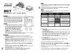
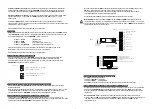
EICT
Installation and set-up guide
DESCRIPTION
Models
EICT
&
EICTM
are specialist driver/signal conditioning units for
Penny + Giles'
ICT
and
SLT
range of linear displacement transducers.
These modules incorporate a high performance circuit that drives the
transducer and provides a choice of output signals, with zero and gain
adjustment for simple user configuration. The module can be supplied
in a choice of enclosures, with sealing to IP66 (EICT) or IP68 (EICTM)
protection. For the full product specifications, refer to the
EICT/EICTM
data sheets in the relevant transducer product brochure.
MOUNTING
•
The
EICT
module has a dual mounting option. It can be mounted
on a bulkhead within 10m of the transducer, by using 4 x M5 cap
head screws, 28mm long (minimum) through the mounting holes
that are located under the housing lid. The recommended screw
tightening torque is 4Nm. Alternatively, the rear box detail is
suitable for mounting on a DIN EN50022 or EN50035 rail.
EICT module is rated to IP66 environmental protection.
•
The
EICTM
module can only be mounted on a bulkhead exactly as
the EICT module.
EICTM module is rated to IP68 environmental protection.
•
The user should also ensure that the rubber seal is properly located in the lid groove prior to re-fitting the
lid after setup. Recommended tightening torque for the lid screws is 2Nm.
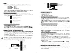
WIRING NOTES
•
These modules will only drive the ICT or SLT transducers correctly when an appropriate Sensor
Calibration Module Card
(SCMC)
is fitted on header
JP1
. The SCMC is supplied within the packaging for
the displacement transducer.
•
EICT module
- The supply, transducer and output connections are routed through two IP66 rated cable
glands that can accommodate cable diameters of between 2.5 and 6mm.
•
EICTM module
- The supply, transducer and output connections are routed through two IP68 rated cable
glands that can accommodate cable diameters of between 3 and 8mm.
•
The user should ensure that the cable glands are tightened sufficiently to ensure cables are clamped and
sealed.
•
Users should also ensure adequate sealing of the opposite end connections on supply, transducer and
output cables to ensure moisture cannot migrate down the inside of the cables into the
EICT/EICTM
module.
•
Connections are made to a screw terminal block on the
EICT/EICTM
circuit board.
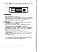
•
The enclosure is not connected internally to ground, so it can be mounted on a chassis carrying a voltage
potential other than 0Vdc.
•
If in doubt about wiring to ground, consult your systems engineer.
•
It is essential that Steps 1 to 7 are completed before connecting a power supply to the
EICT/EICTM. Incorrect connections may destroy the EICT/EICTM on power up.
INNOVATION IN MOTION
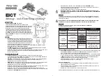
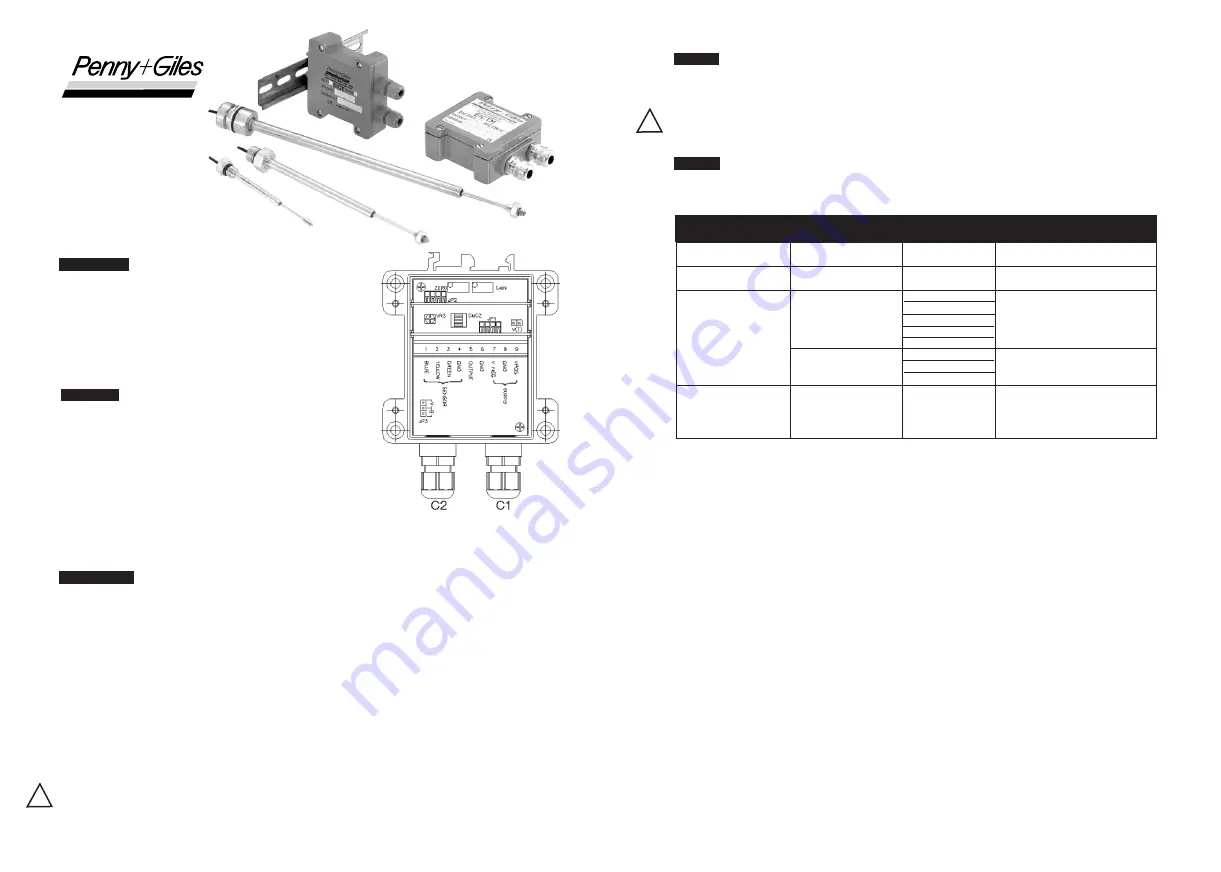
Fig.1
Step 1
Remove the four retaining screws to release the lid from the enclosure base. Note the position of the gasket in
the lid. Identify the Sensor Calibration Module Card
(SCMC)
supplied with the transducer. Insert the
SCMC
card into position
JP1
. (See Fig.1)
Important note: Do not remove the Sensor Calibration Module Card (SCMC) after the calibration
procedure, to ensure proper function of the sensor system!
Step 2
Refer to the Power Supply Voltages v Output Options Matrix chart below to establish the MAXIMUM and
MINIMUM power supply voltage parameters.
CAUTION
!
CAUTION
!
Note A - Dual supply:
•
The
EICT/EICTM
, with or without option cards fitted, requires only a single supply voltage connected
between
GND
and
VPOS
.
When the
VM
(Voltage Module) option card is used, an internal negative rail generator enables zero and
negative output voltages to be achieved.
•
In some situations an external negative supply in the range -10V to -30Vdc may be available (e.g. where
the EICT is being used to replace an earlier model of signal conditioner). It is permissible to connect this
voltage to
VNEG
, in which case the internal negative supply generator on the
VM
option card will be
disabled and current will be drawn from the external supply.
•
To obtain outputs of -10Vdc or -7.5Vdc, the external negative supply should be at least -13.5Vdc.
Note B - Adjustment range:
•
Zero pot approximately 20 turns. Adjustment range = -10% to +60% of nominal sensor range.
•
Gain pot approximately 20 turns. Adjustment range = +40% to +110% of nominal sensor range.
•
Minimum sensor range is 50% of nominal sensor range.
Unscrew the cable glands
C1
&
C2
. (See Fig.1). See note [4] regarding cable diameters.
Single Supply
- Pass the power supply cable through gland
C1
into
'SUPPLY'
zone on the
EICT/EICTM
board.
Connect the power supply lead carrying the most POSITIVE potential (e.g. +24Vdc) to Terminal 9
[VPOS]
.
Connect the power lead carrying 0V to Terminal 8
[GND]
.
Dual Supply
- As Single Supply, BUT, connect most negative power lead (e.g. -15V) to Terminal 7
[VNEG]
. See
note [1] for 4-20mA output.
A power supply cable screen can be connected to Terminal 6
[GND]
. This is recommended but optional.
Consult your systems engineer if other options required.
Firmly tighten cable gland lock nut
C1
.


