background image

Save this manual for future reference.

OWNER’S OPERATION AND INSTALLATION MANUAL

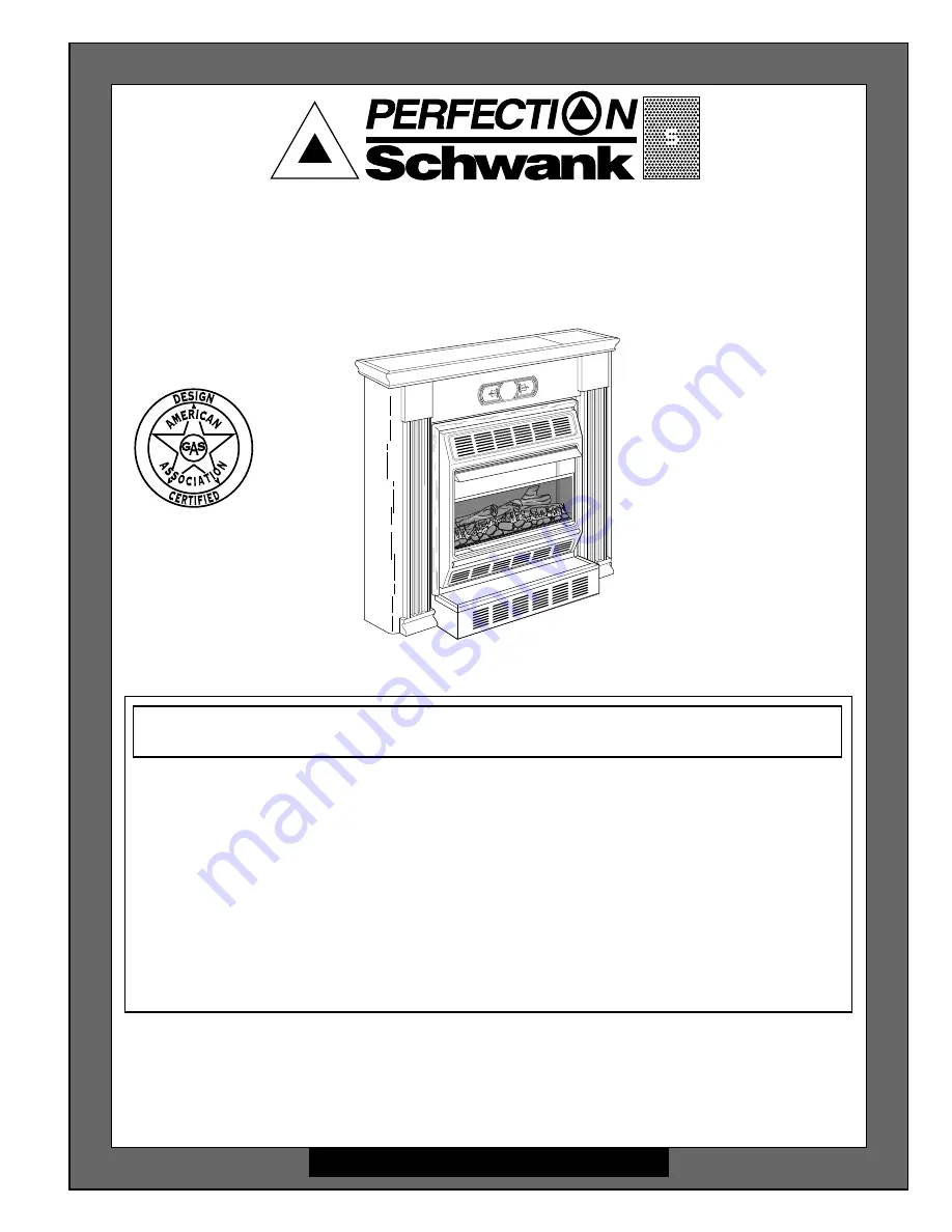
VENT-FREE NATURAL

GAS HEATER

Shown with Optional

Hearth Base and Mantel

WARNING: If the information in this manual is not followed exactly, a fire or
explosion may result causing property damage, personal injury, or loss of life.

— Do not store or use gasoline or other flammable vapors and liquids in the

vicinity of this or any other appliance.

— WHAT TO DO IF YOU SMELL GAS

• Do not try to light any appliance.
• Do not touch any electrical switch; do not use any phone in your building.
• Immediately call your gas supplier from a neighbor’s phone. Follow the gas

supplier’s instructions.

• If you cannot reach your gas supplier, call the fire department.

— Installation and service must be performed by a qualified installer, service

agency, or the gas supplier.

This appliance may be installed in an aftermarket* manufactured (mobile) home,
where not prohibited by state or local codes.

* Aftermarket: Completion of sale, not for purpose of resale, from the manufacturer

This appliance is only for use with the type of gas indicated on the rating plate.
This appliance is not convertible for use with other gases.

®

14,000 to 28,000 Btu/Hr Thermostat

Model: GM280TNG

Summary of Contents for GM280TNG

Page 1: ...rical switch do not use any phone in your building Immediately call your gas supplier from a neighbor s phone Follow the gas supplier s instructions If you cannot reach your gas supplier call the fire department Installation and service must be performed by a qualified installer service agency or the gas supplier This appliance may be installed in an aftermarket manufactured mobile home where not ...

Page 2: ...ion electrical shock and carbon monoxide poisoning WARNING ICON G 001 DANGER Carbon monoxide poisoning may lead to death Carbon Monoxide Poisoning Early signs of carbon monoxide poisoning resemble the flu with headaches dizziness or nausea If you have these signs the heater may not be working properly Get fresh air at once Have heater serviced Somepeoplearemoreaffectedbycarbonmonoxidethanothers Th...

Page 3: ...tion sensor ODS pilot light safety system The ODS shuts down the heater if not enough fresh air is available See Air for Combustion and Ventilation pages 8 through 11 6 If heater shuts off do not relight until you provide fresh outside air If heater keeps shutting off have it serviced 7 Do not run heater where flammable liquids or vapors are used or stored under dusty conditions 8 Never place any ...

Page 4: ...oe m kg o dk irln fg pd fA SD FK IG LF JI als kd idk oe m kg o dk irln fg pd f AS DF KI GL FJ I als kd idk oe m kg o dk irln fg pd fA SD FK IG LF JI als kd idk oe m kg o dk irln fg pd f AS DF KI GL FJ I als kd idk oe m kg o dk irln fg pd fA SD FK IG LF JI als kd idk oe m kg o dk irln fg pd f AS DF KI GL FJ I als kd idk oe m kg o dk irln fg pd A SD FK IG LF JI als kd idk oe m kg o dk irln fg pd f A...

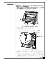
Page 5: ...easier installation lay heater on its back 1 Remove log from inside top of heater Discard protective packaging 2 Attach ignitor cable to piezo ignitor see Figure 3 3 With Phillips screwdriver remove four screws holding screen in place Re move screen 4 Gently slide log between log retaining brackets on deflector assembly see Figure 4 page 6 The log should fit firmly against bottom of log retaining ...

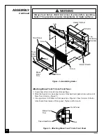
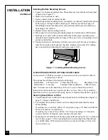
Page 6: ... Front Trim ASSEMBLY Continued Log Heater Cabinet Deflector Burner Shield Screw Screw Brass Front Trim Nut Truss Head Screw Screen Log Retaining Brackets Attaching Brass Front Trim to Front Panel 1 Locate brass front trim in brass trim package 2 Slide the head of two truss head screws from hardware packet into each end of brass front trim see Figure 5 3 Line up screws with holes in front panel see...

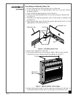
Page 7: ... Figure 6 6 While firmly holding edges of brass trim together tighten both set screws on the adjusting plate with slotted screwdriver Side Brass Trim Top Brass Trim Slot Mitered Edge Slot Set Screws Adjusting Plate Screws Assembled Brass Trim Figure 7 Attaching Brass Trim to Heater 9 Reattach front panel to heater if you are going to mount the heater to the base Do not reattach front panel at this...

Page 8: ...Section 5 3 defines confined space as having an air volume of less than 50 cubic feet 127 cubic cm for each 1000 Btu Hr input rating of all appliances in the space cubic feet equals length x width x height of space Include adjoining rooms only if there are doorless passageways or ventilation grills between the rooms PROVIDING ADEQUATE VENTILATION The following is excerpts from National Fuel Gas Co...

Page 9: ...r ___________________ Btu Hr Gas fireplace logs ___________________ Btu Hr Other gas appliances ___________________ Btu Hr Total ___________________ Btu Hr Example Gas water heater 30 000 Btu Hr Vent free heater 28 000 Btu Hr Total 58 000 Btu Hr Do not include direct vent gas appliances Direct vent draws combustion air from the outdoors and vents to the outdoors 4 Compare the maximum Btu Hr the sp...

Page 10: ...TION AIR Ventilation Air From Inside Building This fresh air would come from an adjoining unconfined space When ventilating to an adjoining unconfined space you must provide two permanent openings one within 12 of the ceiling and one within 12 of the floor on the wall connecting the two spaces see options 1 and 2 Figure 8 You can also remove door into adjoining room see option 3 Figure 8 Follow th...

Page 11: ...ent openings one within 12 of the ceiling and one within 12 of the floor Connect these items directly to the outdoors or spaces open to the outdoors These spaces include attics and crawl spaces Follow the National Fuel Gas Code NFPA 54 ANSI Z223 1 Section 5 3 Air for Combustion and Ventilation for required size of ventilation grills or ducts IMPORTANT Do not provide openings for inlet or outlet ai...

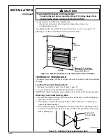
Page 12: ...the heater when using the optional hearth base IMPORTANT Only use optional mantel and hearth base specified in this manual Purchase the optional mantel and hearth base from your dealer See Accessories pages 31 and 32 The heater may also be mounted on a wall You cannot use optional mantel if mounting heater on a wall WARNING ICON G 001 WARNING Never install the heater in a bedroom or bathroom in a ...

Page 13: ... Viewed From Front of Heater THERMOSTAT SENSING BULB The thermostat sensing bulb has been placed inside the heater for protection during shipping Locating Thermostat Sensing Bulb 1 Remove front panel of heater see Figure 2 page 5 2 Locate thermostat sensing bulb just under burner assembly IMPORTANT Attach thermostat sensing bulb to back of heater for proper operation Attaching Thermostat Sensing B...

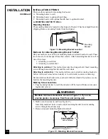
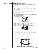
Page 14: ...their centers Attach mounting bracket to wall in one of two ways 1 Attaching to wall stud 2 Attaching to wall anchor Attaching to wall stud This method provides the strongest hold Insert mounting screws through mounting bracket and into wall studs Attaching to wall anchor This method allows you to attach mounting bracket to hollow walls wall areas between studs or to solid walls concrete or masonr...

Page 15: ...s concrete or masonry drill at least 1 deep 2 Fold wall anchor as shown in Figure 14 3 Insert wall anchor wings first into hole Tap anchor flush to wall 4 For thin walls 1 2 or less insert red key into wall anchor Push red key to pop open anchor wings IMPORTANT Do not hammer key For thick walls over 1 2 thick or solid walls do not pop open wings Figure 14 Folding Anchor Continued Figure 15 Popping...

Page 16: ...illips screwdriver slotted screwdriver and electric drill if securing base to floor The optional hearth base kit includes the following Hearth Base 4 Wood Screws 4 Sheet Metal Screws Brass Base Trim Hearth Insert 4 Anchors Laminate Sheet adhesive 2 Brass Screws Note You must secure the hearth base to floor To secure hearth base to floor follow instructions under Securing Hearth Base to Floor below...

Page 17: ...se Trim Brass Base Trim Continued 5 Stand heater up on base 6 Attach laminated insert onto hearth insert if desired see Figure 19 Place hearth insert in hearth base as shown in Figure 19 below 7 Assemble brass trim see steps 1 through 7 under Assembling and Attaching Brass Trim page 7 8 Slide base trim on heater base Attach brass trim to base with two brass screws included as shown in Figure 19 be...

Page 18: ...alves Install sediment trap in supply line as shown in Figure 20 page 19 Locate sediment trap where it is within reach for cleaning Locate sediment trap where trapped matter is not likely to freeze A sediment trap traps moisture and contaminants This keeps them from going into heater controls If sediment trap is not installed or is installed wrong heater may not run properly WARNING ICON G 001 WAR...

Page 19: ...8 NPT Plug Tap Test Gauge Connection Tee Joint Pipe Nipple Cap Sediment Trap Pressure Regulator 1 2 NPT Pipe Nipple Ground Union Joint Heater Cabinet 3 Minimum Note Burner bracket not shown for clarity Manual Shutoff Valve From Gas Meter 4 W C to 10 5 W C Pressure CONNECTING TO GAS SUPPLY Continued CHECKING GAS CONNECTIONS Figure 20 Gas Connection An A G A design certified manual shutoff valve wit...

Page 20: ...TESTING HEATER GAS CONNECTIONS 1 Open manual shutoff valve see Figure 21 2 Open main gas valve located on or near gas meter 3 Make sure control knob of heater is in the OFF position 4 Check all joints from manual shutoff valve to thermostat gas valve see Figure 22 Apply mixture of liquid soap and water to gas joints Bubbles forming show a leak 5 Correct all leaks at once 6 Light heater see Operati...

Page 21: ...ver use tools If the knob will not push in or turn by hand don t try to repair it call a qualified service technician or gas supplier Force or attempted repair may result in a fire or explosion D Do not use this appliance if any part has been under water Immediately call a qualified service technician to inspect the appliance and to replace any part of the control system and any gas control which ...

Page 22: ... Note If pilot does not stay lit refer to Troubleshooting pages 26 through 29 Also contact a qualified service person or gas supplier for repairs Until repairs are made light pilot with match To light pilot with match see Manual Lighting Procedure page 23 7 Keep control knob pressed in for 30 seconds after lighting pilot After 30 seconds release control knob If control knob does not pop up when re...

Page 23: ...s the room may exceed the set temperature If so the burner will shut off The burner will cycle back on when room temperature drops below the set temperature The control knob can be set to any heat level between HI and LO Note The thermostat sensing bulb measures the temperature of air near the heater cabinet This may not always agree with room temperature depending on housing construction installa...

Page 24: ...t flame is not touching the thermocouple This will cause the thermocouple to cool When the thermocouple cools the heater will shut down Thermocouple Pilot Burner Figure 25 Correct Pilot Flame Pattern Bad Pilot Nat Port GRH OV 007E Pilot Burner Thermocouple Figure 26 Incorrect Pilot Flame Pattern If pilot flame pattern is incorrect as shown in Figure 26 turn heater off see To Turn Off Gas to Applia...

Page 25: ...er the heater and burn causing brief patches of orange flame If burner flame pattern is incorrect as shown in Figure 28 turn heater off see To Turn Off Gas to Appliance page 23 see Troubleshooting pages 26 through 29 CORRECT FLAME PATTERN AT HIGH POSITION INCORRECT FLAME PATTERN AT HIGH POSITION Yellow Tipping Figure 27 Correct Burner Flame Pattern Figure 28 Incorrect Burner Flame Pattern Top of F...

Page 26: ...repair heater WARNING ICON G 001 CAUTION You must keep control areas burner and circulating air passage ways of heater clean Inspect these areas of heater before each use Have heater inspected yearly by a qualified service person Heater may need more frequent cleaning due to excessive lint from carpeting bedding material etc WARNING ICON G 001 WARNING Turn off heater and let cool before cleaning P...

Page 27: ...pilot assembly 7 Replace thermocouple 8 Replace control valve OBSERVED PROBLEM When ignitor button is pressed there is spark at ODS pilot but no ignition ODS pilot lights but flame goes out when control knob is released POSSIBLE CAUSE 1 Gas supply turned off or manual shutoff valve closed 2 Control knob not in PILOT position 3 Control knob not pressed in while in PILOT position 4 Air in gas lines ...

Page 28: ...and Mainte nance page 26 2 Replace gas regulator 1 Problem will stop after a few hours of operation 1 Turn control knob to LO position and let warm up for a minute 2 Operate burner until air is removed from line Have gas line checked by local natural gas company 3 Observe minimum installation clearances see Figure 10 page 13 4 Clean burner see Cleaning and Mainte nance page 26 or replace burner or...

Page 29: ...MEDY 1 This is common with most heaters If noise is excessive contact qualified service person 1 Ventilate room Stop using odor causing products while heater is running 2 Locate and correct all leaks see Checking Gas Connections page 19 1 Open window and or door for ventilation 2 Contact local natural gas company 3 Clean ODS pilot see Cleaning and Mainte nance page 26 1 Locate and correct all leak...

Page 30: ... at 1 800 776 8459 outside GA or 706 554 2101 for referral information When calling Perfection Schwank have ready your name your address model number of your heater how heater was malfunctioning type of gas used propane LP or natural gas purchase date Usually we will ask you to return the defective part to the factory Parts Not Under Warranty Contact authorized dealers of this product If they can ...

Page 31: ...54 2101 for information You can also write to the address listed on the back page of this manual FAN KIT GM28BL Provides better heat distribution Makes heater more efficient Complete installation and operating instruc tions included HEARTH BASE GM28BA For locating heater on the floor Includes brass trim and reversible black metal sandstone laminate filler Complete installation instruc tions includ...

Page 32: ...arved rope trim Available in a walnut finish ready to stain or paint Complete assembly and installation instructions included UNFINISHED MANTEL GM280MU For use with heater and hearth base Sturdy hardwood construc tion embellished with fluted sides Available in an unfinished hard wood ready to stain or paint Complete assembly and installa tion instructions included ...

Page 33: ...33 103092 12 1 12 2 1 2 9 10 10 11 12 13 14 15 16 17 19 20 21 22 23 24 25 26 27 28 8 6 7 18 1 3 5 4 30 29 1 GM280TNG ...

Page 34: ...4 01 Ignitor Electrode 1 13 099126 02 Burner 1 14 098517 01 3 16 Pilot Tubing 1 15 098251 04 Injector 1 16 098250 01 Injector Holder 1 17 098867 04 Pressure Regulator 1 18 099553 01 Pilot Shield 1 19 098299 02 3 8 Outlet Burner Tubing 1 20 098297 03 3 8 Inlet Tubing 1 21 098264 02 3 8 NPT Male Connector 1 22 098276 01 1 8 NPT Plug 1 23 098277 01 3 8 to 1 8 NPT Bushing 1 24 098265 01 3 8 NPT Male E...

Page 35: ..._________ _________________________________________________________________ _________________________________________________________________ _________________________________________________________________ _________________________________________________________________ _________________________________________________________________ ____________________________________________________________...

Page 36: ...o repairing a defective heater will be the responsibility of the owner TO THE FULL EXTENT ALLOWED BY THE LAW OF THE JURISDICTION THAT GOVERNS THE SALE OF THE PRODUCT THIS EXPRESS WARRANTY EXCLUDES ANY AND ALL OTHER EXPRESSED WARRANTIES AND LIMITS THE DURATION OF ANY AND ALL IMPLIED WARRANTIES INCLUDING WARRANTIES OF MERCHANTABILITY AND FITNESS FOR A PARTICULAR PURPOSE TO ONE 1 YEAR ON ALL COMPONEN...

Reviews: