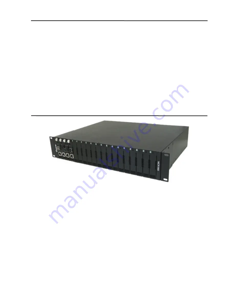
background image

MCR1900

Media Converter

19-Slot Chassis

Installation Guide

Part #5500304-10

Summary of Contents for MCR1900

Page 1: ...MCR1900 Media Converter 19 Slot Chassis Installation Guide Part 5500304 10...

Page 2: ...rules These limits are designed to provide reasonable protection against harmful interference when the equipment is operated in a commercial environment This equipment generates uses and can radiate...

Page 3: ...s 9 Intelligent Alarm Relay 9 Media Converter Modules 10 Chapter 2 Installing the MCR1900 11 Site Preparation Requirements 11 Grounding the MCR1900 Chassis 12 Installing the Media Converter Modules 13...

Page 4: ...ower Supply Module 19 Removing the Power Supply Module 19 Installing or Replacing the Power Supply Module 20 Appendix A Technical Specifications 22 Environmental Specifications 22 Physical Specificati...

Page 5: ...is for administrators who will be installing the MCR1900 Documentation The following documentation is included with the MCR1900 z MCR1900 Media Converter 19 Slot Chassis Installation Guide Where to f...

Page 6: ...ices_request shtml To chat live with a Technical Support Representative use the link below http www perle com chattechsupp shtml Product Information For more product details and information about Perl...

Page 7: ...for Media Converter Modules z Support for all Perle Media Converter Modules z Media Converter Modules are individually secured and hot swappable for maximum connection reliability z Dual hot swappabl...

Page 8: ...can be met with one Power Supply however a second Power Supply can be added for power redundancy and load sharing If the Chassis has two Power Supply Modules the modules will use a load sharing arran...

Page 9: ...the Chassis Off z The Power Supply Module has been switched Off z The power plug has been removed z No power at power source z The Power Supply Module has failed Slow Blinking Only applies to a Dual P...

Page 10: ...9 32 5 16 using stranded wire size 18 12 AWG Tighten screw to a torque of 4 5 lb per inch 0 51 Nm Media Converter Modules For information regarding Media Converter Installation see the appropriate Ins...

Page 11: ...ts and connectors on the front and back of the Chassis so that you can connect and disconnect cables as well as view the LEDs z The power outlet s should be located near the Chassis and supply reliabl...

Page 12: ...ed z If placing the Chassis on a table make sure the table is level and secure Grounding the MCR1900 Chassis The MCR1900 should always be grounded for safe and proper operation Grounding the Chassis r...

Page 13: ...Converter Modules To install or remove a Perle Media Converter Module refer to page 15 in this guide Connecting the Alarm Relays optional The MCR1900 provides a method of allowing you to connect an e...

Page 14: ...tlet repeat this procedure if you have a second power supply installed in the Chassis 3 Turn the power switch s to the On position Power Supply LED Status Description LED On solid Indicates that the p...

Page 15: ...tion NOTE This is an indication of a potential hazard The power switch should be immediately turned off and the power disconnected Note For your safety before attempting to connect or modify any of th...

Page 16: ...16...

Page 17: ...If installing or replacing your Media Converter Module remove the Media Converter Module from its packaging 2 Using a cross head screwdriver remove the screw holding the face plate to reveal the slot...

Page 18: ...the module s backplane conector is not damaged retry the insertion 6 Tighten the Captive retainer screw to ensure the Media Converter Module is locked in place 7 Remove the dustcap from the fiber conn...

Page 19: ...rom its source 3 Disconnect the power cord from the MCR1900 Power Supply Module 4 Disconnect the alarm relay connections if connected 5 Using a screwdriver remove the one screw located at the top of t...

Page 20: ...h with the back of the Chassis Light pressure may be needed to seat the module Do not force the module as you might damage the connector If there is resistance remove the module and try again 5 Using...

Page 21: ...21 For Power Module LED status see page 14 in this guide Note All Bay openings must be covered with or a Power Supply Bay cover in order to maintain proper air circulation throughout the Chassis...

Page 22: ...e of 2000 m 6500 ft Physical Specifications Operating Temperature 0 oC to 50 oC 32 oF to 122 oF Storage Temperature 25 o C to 70 o C 13 o F to 150 o F Operating Storage Humidity 5 to 95 non condensing...

Page 23: ...23 Power Specifications MCR1900 Chassis with Power Supply Module Nominal Input Voltage 100 to 240 V AC Input Voltage range 90 to 264 V AC AC Input Frequency 50 to 60 Hz Capacity 2 A...

Page 24: ...emoved z No power at power source z The Power Supply Module has failed Slow Blinking Only applies to a Dual Power Supply Chassis The Power Supply Modules are establishing load sharing parameters Fast...

Page 25: ...of power source to the Power Supply Module z Power switch is in the Off position z Power Supply Module hardware failure Fan not running z The fan is running at less then 50 speed rate z The fan has fa...

Reviews: