background image

perma-tec GmbH & Co. KG

perma Produktname

perma-tec GmbH & Co. KG

The World of Automatic Lubrication

perma PRO

perma-tec GmbH & Co. KG

The World of Automatic Lubrication

perma PRO

This operating manual is valid for the lubricator perma PRO with PRO LC-units 250 cc and 500 cc.

© 

2002 perma-tec GmbH & Co. KG

Without the specific approval of perma-tec GmbH & Co. KG no part of this documentation

can be copied or made available to third parties.

We have taken great care when compiling all the details contained in this documentation.
However, we cannot rule out discrepancies and we reserve the right to make technical 
changes to the product without giving advance notice.
We do not assume any judicial responsibility or liability for damages which may ensue as 
a result.
We will include any necessary changes in the next edition.

Compiled and printed:   

01 / 01 / 2008

Operating Instructions

perma

PRO 250 / 500

Summary of Contents for PRO 250

Page 1: ...H Co KG no part of this documentation can be copied or made available to third parties We have taken great care when compiling all the details contained in this documentation However we cannot rule out discrepancies and we reserve the right to make technical changes to the product without giving advance notice We do not assume any judicial responsibility or liability for damages which may ensue as...

Page 2: ...en LED starts blinking 6 Stopping perma PRO refer chapter 6 6 Keep the ON OFF SELECT button pressed until the display shows _ _ Display Drive Unit Protection cover With bayonet catch for quick opening closing PRO LC Unit Lubrication Canister Cartridge piston spindle filled with lubricant Red LED Additional malfunction indication Push Button MODE SAVE Leads to the Configuration Menu and saves the s...

Page 3: ...ments of the Lubrication System 12 5 1 Display Elements 5 2 Function Indication on the Display 5 3 Function Indication via the LEDs 5 4 Control Buttons 6 Operation and Control 13 6 1 Preparations 6 2 Prior to Operation 6 3 Setting into Operation 6 4 During Operation 6 5 Switching the Lubrication System On 6 6 Switching the Lubrication System Off 6 7 Determining the Discharge Period 6 8 Settings an...

Page 4: ...lth or to subjects Tips This sign alerts you to application tips which will help you in doing certain tasks quicker and safer 1 1 Delivery Content perma PRO will be delivered according to customer specifications in regards to type of grease and size of PRO LC unit The user must only assemble it and adjust the desired settings Mounting device and screws included Operating instructions and EC Confor...

Page 5: ...ginal lubrication tubes from perma tec GmbH Co KG is intended for use on machinery and equipment is only to be used for the ordered purpose and purposes confirmed by perma tec is only to be used for operating conditions recommended in this operating manual is only to be used with settings and variations recommended in this operating manual Any other usage setting addition and variation is consider...

Page 6: ... be consulted first Only original tube connections and connectors from perma tec can be used on or with the lubrication system since these will withhold high pressures of up to 25 bar 360psi Ambient media especially chemically aggressive substances can attack seals and plastic 2 3 Safety Information for perma PRO Safety during Installation and Maintenance Ensure that all workstations and traffic r...

Page 7: ...ths Discharged volume per lubrication impulse 0 5 cc Application temperature 20 C to 60 C 4 F to 140 F Maximum pressure build up 25 bar 360 psi Maximum tube length inner Ø 5mm 5 m Lubricants Greases up to rated consistency NLGI 2 Power supply 0 C to 60 C 32 F to 140 F Battery set PRO B 3 V alkaline manganese not rechargeable Power supply low temperature 20 C to 60 C 4 F to 140 F Battery set PRO B ...

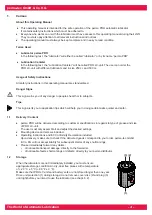
Page 8: ...t re usable PRO LC unit Lubrication Canister can be supplied as 250 cc and 500 cc versions with the lubricant requested by the customer Usage of perma pro PRO LC units only Battery set consisting of two batteries The batteries are not rechargeable and must be changed every time the PRO LC unit is replaced Batteries can only be used once Usage of perma tec battery sets only Drive unit consisting of...

Page 9: ...ure that the lubrication points and the complete lubricant tube is pre lubricated with the same lubricant that is contained in the PRO LC unit For that perma tec offers a 400 g lubrication cartridge for manually operated grease presses with the requested lubricant Connect the lubricant tube connection G 3 8 outside or G 1 8 inside to the outlet of the drive unit and install the tube correctly betw...

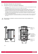
Page 10: ...rive unit according to the direction of the arrow on the label No function Setting of PRO LC unit size is done via menu on display Battery set Catch Interlocking teeth b Place the PRO LC unit inside the protection cover and remove the plug of the PRO LC unit refer to figure 5 figure 5 Protection cover PRO LC unit Plug figure 4 ...

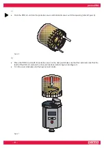
Page 11: ... opening refer to figure 6 figure 6 d Place the PRO LC unit with its protection cover on the drive unit Make sure that the catch locks and that the teeth of the PRO LC unit and the drive unit interlock refer to figure 4 and figure 7 Turn the cover clockwise until the bayonet catch locks figure 7 ...

Page 12: ...ges of the lubricator In case of an error free operation of the lubrication system the display shows the remaining volume of the mounted PRO LC unit in percent volume Vol Figure 9 shows an example of the displayed information if the PRO LC 500 unit is new and full The display cannot be switched off by the operator If the lubrication system is switched off the display will always show two lines see...

Page 13: ...maximum of 5 meters and the tube must be a perma tec product Please check if the thread of the perma PRO G 3 8 or G 1 8 corresponds to the connection thread of the lubrication point If this is not the case you can order a corresponding reducer or other parts from the perma accessory range For the initial setting into operation of a perma PRO the pump system in the drive unit is pre filled with SF ...

Page 14: ... level of the transparent PRO LC unit regularly After one or several additional discharges you have to calculate the reduced discharge period and note this on your lubrication and maintenance schedule If a malfunction is indicated on the display you can determine the cause using the trouble shooting guide refer to chart 7 chapter 8 2 If the fault cannot be fixed please contact your supplier for te...

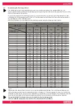
Page 15: ...ur calculation of the remaining discharge period in your lubrication and maintenance schedule The perma SELECT software helps you to determine the discharge period Visit our website www perma tec com for a free download of this software Average discharge volume in cc per 100 operating hours PRO LC unit 250 500 Days Weeks Months Days Weeks Months 1 1041 7 148 8 34 3 2083 3 297 6 68 5 2 520 8 74 4 1...

Page 16: ...Outlet 2 On Off Outlet 2 activated if desired other outlets may be turned On Off the same way Change first digit PIN first digit enter for initial configuration or after a PIN reset otherwise setting is complete PIN Change second digit PIN second digit enter for initial configuration or after a PIN reset Configuration finished chart 5 5 MODE SAVE MODE SAVE MODE SAVE MODE SAVE MODE SAVE MODE SAVE M...

Page 17: ...anges to settings that are currently displayed in the configuration menu LC Time Outlets PIN press the ON OFF SELECT button until the display shows either for Off or the remaining volume of the PRO LC unit in VOL All other settings and already saved changes remain valid Automatic Termination of the Configuration Mode If you do not press a button in the configuration menu for 180 seconds the contro...

Page 18: ...ring the shut off will be caught up when the system continues operation at a max of two additional discharges with every regular discharge 6 9 Calculation of the Remaining Discharge Period Please note that in case of one or several additional discharges the remaining discharge period of the lubrication system must be recalculated This also applies in case of a cut off of the lubrication system due...

Page 19: ...sture an exchange may only be carried out in dry conditions After the installation of the new PRO LC unit the control system continues to operate using the previously valid setting of the discharge period 7 1 Setting the Volume of the PRO LC Unit The size of the PRO LC unit must be set in the configuration menu with the two buttons on the drive unit see figure 18 Please also refer to the operating...

Page 20: ...nt comes out of the opening refer to figure 6 chapter 4 g Place the new PRO LC unit on the drive unit turn it until the catch locks and the teeth of the PRO LC unit and the drive unit interlock The control system automatically recognizes the new PRO LC unit The display indicates _ _ if the perma PRO was switched off prior to the replacement of the PRO LC unit Or it indicates 99 Vol if the perma PR...

Page 21: ...rent of the lubricator motor caused by a blocking of the displayed outlet Clear the blockage and acknowledge the fault by pushing and holding down the ON OFF SELECT button E2 Lubrication system has been switched off Outlets of distributor not correctly recognized Replace distributor E3 Lubrication system has been switched off Timeout while activating distributor Connection cable damaged Replace di...

Page 22: ... parts and accessories from perma tec Spare parts Part No Illustration PRO LC unit 250 cc filled with lubricant 2220 XXX 608 XXX grease number PRO LC unit 500 cc filled with lubricant 2230 XXX 609 XXX grease number Protection cover 250 cc made of transparent plastic Protection cover 250 cc made of aluminium for applications with ester containing lubricants 2299 101 000 2299 102 001 Protection cove...

Page 23: ... Straight connecting piece G 1 8 for lubricant tubes 27 008 010 Angle G 1 8 for connecting a lubricant tube 27 008 011 Special lubricant tube Ø 8 x 1 5 inner Ø 5 mm with different lengths 27 008 009 Reducer G 3 8 G 1 4 27 008 017 CD ROM with SELECT software calculation of the lubricant amount lubrication and maintenance schedule and operating instructions as PDF file on request chart 8b ...

Page 24: ...valuable raw material Please follow your local waste disposal regulations 11 Service Please contact your local supplier for availability and cost of the following Returning of the empty lubricator for environmentally safe recycling or disposal or exchange of battery set exchange of PRO LC unit to pre set lubricator LC lubrication period outlets ...

Page 25: ... Lubricator perma PRO Type perma PRO 250 and perma PRO 500 The following harmonised standards were applied EN ISO 12100 1 2003 Safety of machinery basic concepts general terms of reference as regards design and construction Section 1 Basic Terminology Methodology EN ISO 12100 2 2003 Safety of machinery basic concepts general terms of reference as regards design and construction Section 2 Technical...

Page 26: ...08 01 01 perma tec GmbH Co KG The World of Automatic Lubrication perma PRO perma tec GmbH Co KG Internet www perma tec com E mail info perma tec com ...

Reviews: