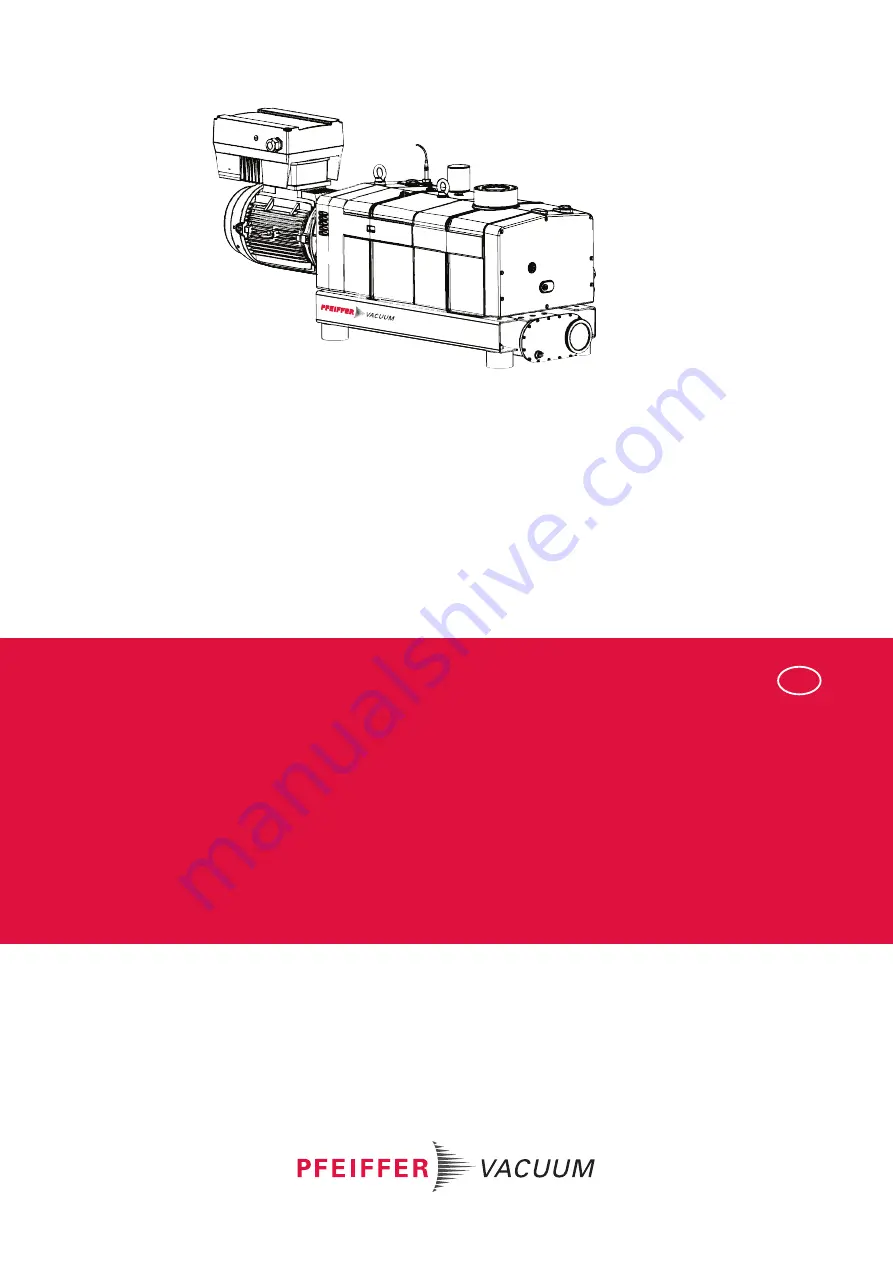
background image

OPERATING INSTRUCTIONS

EN

Translation of the Original

HEPTA 950 L

Screw pump with integrated frequency converter

Summary of Contents for HEPTA 950 L

Page 1: ...OPERATING INSTRUCTIONS EN Translation of the Original HEPTA 950 L Screw pump with integrated frequency converter ...

Page 2: ...er vacuum de Further operating instructions from Pfeiffer Vacuum can be found in the Download Center on our website Disclaimer of liability These operating instructions describe all models and variants of your product Note that your product may not be equipped with all features described in this document Pfeiffer Vacuum constantly adapts its products to the latest state of the art without prior no...

Page 3: ... cooling 17 3 1 2 Temperature monitoring 17 3 1 3 Frequency converter 18 3 1 4 Gas ballast 18 3 1 5 Sealing gas system 18 3 1 6 Silencer 18 3 2 Identifying the product 18 3 3 Product features 18 3 4 Scope of delivery 18 4 Transportation and Storage 19 4 1 Transport 19 4 2 Bearing 20 5 Installation 21 5 1 Setting up the vacuum pump 21 5 2 Connecting the vacuum side 21 5 3 Connecting exhaust side 22...

Page 4: ... Cleaning the gas ballast filter 39 8 Decommissioning 41 8 1 Decommissioning the vacuum pump 41 8 2 Recommissioning 41 9 Recycling and disposal 43 9 1 General disposal information 43 9 2 Disposing of the screw pump 43 10 Malfunctions 44 11 Service solutions by Pfeiffer Vacuum 46 12 Accessories 48 12 1 Accessory information 48 12 2 Order accessories 48 12 3 Consumables 48 13 Technical data and dime...

Page 5: ...l 6 Prerequisites for the cooling water 24 Tbl 7 Requirements for the sealing gas supply 24 Tbl 8 Technical data 29 Tbl 9 Maintenance intervals 34 Tbl 10 Troubleshooting 45 Tbl 11 Accessories 48 Tbl 12 Consumables 48 Tbl 13 Conversion table Pressure units 49 Tbl 14 Conversion table Units for gas throughput 49 Tbl 15 Technical data for Hepta 950 L 50 Tbl 16 Materials that make contact with the proc...

Page 6: ...ling lubricant on the vacuum side 26 Fig 10 Connecting power supply to the frequency converter 28 Fig 11 Connecting temperature switch 29 Fig 12 Checking the lubricant level 35 Fig 13 Draining lubricant on the motor side 36 Fig 14 Draining lubricant on the vacuum side 37 Fig 15 Filling lubricant on the motor side 37 Fig 16 Filling lubricant on the vacuum side 38 Fig 17 Disassembling and cleaning t...

Page 7: ...se instructions You can find this document in the Pfeiffer Vacuum Download Center 1 1 2 Variants These instructions are applicable for HeptaDry vacuum pumps Pump type Pump version Hepta 950 L Dry compressing screw pump nominal pumping speed up to 950 m3 h Frequency converter Size Motor rating INVEOR M D 22 kW 1 2 Target group This operating instructions is intended for persons who transport instal...

Page 8: ... 2019 PU V72 0007 001 Rating plate example Rating plate for the screw pump Mod xxx Mod Nr PT 35S 235 Mass 55 kg n xxxx 1 min Motor rating plate Rating plate of the motor Warning hot surface This sticker warns of injuries caused by high tempera tures as a result of contact without protection during op eration Operating instructions note This sticker indicates that this operating instructions must b...

Page 9: ... 4 Rating plate of frequency converter 1 3 4 Abbreviations Abbreviation Meaning in this document OI Operating instructions FCR Fluorocarbon rubber N N Mean sea level PE Protective earth earthed conductor WAF Width across flats SLM Standard liter per minute T Temperature switch VCI Volatile Corrosion Inhibitor Tbl 2 Abbreviations used in this document 1 4 Trademark proof INVEOR M is a registered tr...

Page 10: ...ndicate important information about the product or about this docu ment 2 2 Safety instructions All safety instructions in this document are based on the results of the risk assessment carried out in accordance with Machinery Directive 2006 42 EC Annex I and DIN EN ISO 12100 Section 5 Where ap plicable all life cycle phases of the product were taken into account Risks during transport WARNING Risk...

Page 11: ...a risk to life Make sure that electrical installations are only carried out by trained electricians who are familiar with the relevant safety instructions for electrical safety and EMC WARNING Danger of injury due to exposed rotating parts Danger of crushing fingers and hands when the vacuum connection is open Safely disconnect motor from the mains Secure the motor against reactivation Never inser...

Page 12: ...e the frequency converter after disconnecting the power supply There is a risk of electric shock if touched Before working on the frequency converter disconnect the mains cable from the mains power supply Wait at least 10 minutes after switching off the frequency converter before you start work Provide adequate grounding for the device Prior to installation check that the connection leads and term...

Page 13: ...range of rotating parts Safely disconnect motor from the mains Secure the motor against reactivation Dismantle the vacuum pump for inspection away from the system if necessary CAUTION Danger of burns on hot surfaces In the event of a fault the surface temperature of the vacuum pump can increase to above 105 C Allow the vacuum pump to cool down before carrying out any work Wear personal protective ...

Page 14: ... the above shutdown procedures Keep lines and cables away from hot surfaces 70 C Never fill or operate the unit with cleaning agents or cleaning agent residues Do not carry out your own conversions or modifications on the unit Observe the unit protection class prior to installation or operation in other environments Provide suitable touch protection if the surface temperature exceeds 70 C 2 4 Limi...

Page 15: ...d all applicable documents in particular the safety maintenance and repair information 2 7 1 Ensuring personnel qualification Specialist for mechanical work Only a trained specialist may carry out mechanical work Within the meaning of this document special ists are people responsible for construction mechanical installation troubleshooting and maintenance of the product and who have the following ...

Page 16: ... Maintenance level 1 Customer with technical education Pfeiffer Vacuum service technician Maintenance level 3 Pfeiffer Vacuum service technician Safety 16 52 ...

Page 17: ...pective application 1 2 3 4 5 7 8 9 10 6 12 13 14 15 16 17 18 19 20 11 Fig 3 Arrangement of screw pump 1 Frequency converter 11 Cooling water outlet 2 Eye bolt 2x 12 Filler screw 3 Thermal circuit breaker 13 Magnetic sealing plug 4 Vacuum connection 14 Sealing gas connection 5 Filler screw 15 Drain screw 6 Locking screw for screw rotors 16 Cooling water drain screw 7 Magnetic sealing plug 17 Drain...

Page 18: ...he motor and bear ing area The supply is carried out either via a sealing gas valve or a sealing gas throttle without control 3 1 6 Silencer The silencer reduces the noise level during operation without exhaust line 3 2 Identifying the product To ensure clear identification of the product when communicating with Pfeiffer Vacuum always keep all of the information on the rating plate to hand Observe...

Page 19: ...orizontally Always transport the screw pump without lubricant Only fill up lubricant at the final installation location Preparations for transport Pfeiffer Vacuum recommends keeping the transport packaging and original protective cov er General information regarding safe transport 1 Observe the weight specified on packaging 2 Use transport equipment e g fork lift truck or lift truck 3 Where possib...

Page 20: ...er Vacuum recommends storing the products in their original transport packaging Store the vacuum pump 1 Seal the vacuum and exhaust connection 2 Make sure that the gas ballast valve is closed 3 Store the vacuum pump only in dry dust free rooms within the specified ambient conditions 4 In rooms with humid or aggressive atmospheres Hermetically seal the vacuum pump together with a drying agent in a ...

Page 21: ...nnection NOTICE Property damage from contaminated gases Pumping gases that contain contamination damages the vacuum pump Use suitable filters or separators from the Pfeiffer Vacuum range of accessories to protect the vacuum pump NOTICE Property damage from intake of solid particles During commissioning there is a risk of damage to the suction chamber from dirt from the system or the pipes Use a su...

Page 22: ... side Overpressure or un derpressure are not permissible Check the function of the exhaust line on a regular basis Connecting the exhaust side Do not close or throttle the exhaust line The discharged gas must be permitted to stream out unhindered Choose a minimum diameter equal to the nominal diameter of the exhaust connection Do not use the exhaust line as a source of compressed air Support or su...

Page 23: ...Cooling system evacuated 1 2 Fig 6 Cooling water connection 1 Cooling water inlet 2 Cooling water outlet Connecting cooling water supply 1 Connect the cooling water connections with the water supply Connection size 1 2 thread ISO 228 1 2 Open the water inflow Parameter Cooling water Appearance filtered mechanically clear visually clear no turbidity no sediment free from grease and oil pH value 7 t...

Page 24: ...aling gas connection 1 Inferential meter 3 Sealing gas connection 2 Pressure regulating valve 4 Pressure gauge Procedure 1 Connect the sealing gas connection to the gas supply Connection size 1 4 thread ISO 228 1 Use the gas cylinder with pressure reducer and inferential meter 2 Set the sealing gas amount in accordance with the table Gas type Dry nitrogen or air Gas temperature 0 60 C Max gas pres...

Page 25: ...k on the sight glass Sticker for lubricant change Note the date of the lubricant change Contact Pfeiffer Vacuum if you need a new sticker The lubricant type is specified on the rating plate 1 Please refer to rating plate of the vacuum pump for type and quantity of intended lubricant 2 Only use the lubricant which was applied during initial installation Contact Pfeiffer Vacuum if you want to use an...

Page 26: ... life from electric shock Touching exposed and voltage bearing elements causes an electric shock Improper connection of the mains supply leads to the risk of touchable live housing parts There is a risk to life Before the installation check that the connection leads are voltage free Make sure that electrical installations are only carried out by qualified electricians Provide adequate grounding fo...

Page 27: ... starting up does not cause a hazardous situation Maintain sufficient distance to the vacuum flange during all work NOTICE Risk of damage from excess voltage Incorrect or excessive mains voltage will destroy the motor Always observe the motor rating plate specifications Route the mains connection in accordance with locally applicable provisions Always provide a suitable mains fuse to protect the m...

Page 28: ... phase 2 Grounding cable Procedure Implement the power connection as described in the associated INVEOR M frequency converter operating instructions 5 8 Connecting the operating temperature monitoring The thermal circuit breaker monitors the operating temperature of the vacuum pump Installation 28 52 ...

Page 29: ...lly connect the temperature switch as follows If the temperature exceeds the switch point an alarm is triggered and the vacuum pump switches off 2 Configure a delay of at least 20 seconds on the control system to avoid false alarms Thermal circuit breaker Voltage supply U 250V AC DC 50 60 Hz Current consumption I 1A Connection M12 x 1 4 pin Switch point T 70 C Tbl 8 Technical data Installation 29 ...

Page 30: ...parators from the Pfeiffer Vacuum range of accessories to protect the vacuum pump Before switching on 1 Inspect the screw pump for visible damage and ensure that the screw pump is only operated when in a sound condition 2 Check the fill level of the lubricant on the motor side and vacuum side Top up lubricant as re quired 3 Compare the voltage and frequency specifications on the motor rating plate...

Page 31: ...en atmospheric pressure and final pres sure as required 3 Allow the screw pump to warm up for approx 30 minutes with the vacuum flange closed prior to starting the process 4 Measure the motor current and make a note of the value as reference for future maintenance work and troubleshooting 6 3 Switching off the vacuum pump Procedure 1 Close the shut off valve in the vacuum line and isolate the scre...

Page 32: ...ency converter disconnect the mains cable from the mains power supply Wait at least 10 minutes after switching off the frequency converter before you start work Provide adequate grounding for the device Prior to installation check that the connection leads and terminals are voltage free After connection work carry out an earthed conductor check WARNING Health hazard through poisoning from toxic co...

Page 33: ... supply e g the sealing gas supply 6 Vent the screw pump to atmospheric pressure via the vacuum side 7 Allow the cooling water to drain completely 8 Disconnect all connections 9 Dismantle the screw pump from the system as necessary 7 2 Checklist for inspection and maintenance Notes on maintenance intervals The times for the maintenance intervals depend to a great extent on the process condi tions ...

Page 34: ...nd clean as nec essary If installed inspect silencer and clean as necessary If installed inspect dust filter and re place as necessa ry If installed inspect safety valve and clean as necessa ry Clean magnetic sealing plug Suitable cleaning agent com patible with the process Dust filter Change the lubricant Lubricant Check electric connec tions and monitoring equipment Maintenance level 3 overhaul ...

Page 35: ...o locally applicable regulations CAUTION Scalding from hot lubricant Danger of scalding when draining lubricant if it comes into contact with the skin Wear protective equipment Use a suitable collection receptacle NOTICE Property damage from using non approved lubricant Attainment of product specific performance data is not ensured If non approved lubricants are used all liability and warranty cla...

Page 36: ...pump switched off and cooled Vacuum pump vented Required consumables Lubricant Required tools Ring spanner WAF 8 Ring spanner WAF 22 Open end wrench WAF 38 Required aids Cleaning cloth Collection receptacle Funnel optional 7 4 1 Draining lubricant on the motor side 1 3 2 Fig 13 Draining lubricant on the motor side 1 Magnetic sealing plugs 3 Drain screw 2 Collection receptacle Procedure 1 Place a c...

Page 37: ...ion receptacle beneath the drain hole on the vacuum side 2 Unscrew the drain screw 3 Unscrew the magnetic sealing plug 4 Fully drain the lubricant 5 Clean the magnetic sealing plug 6 Screw in the magnetic sealing plug and drain screw 7 4 3 Filling lubricant on the motor side MAX MIN 1 3 2 Fig 15 Filling lubricant on the motor side 1 Filler screw 3 Sight glass 2 O ring Maintenance 37 52 ...

Page 38: ... 3 Sight glass 2 O ring Procedure 1 Unscrew the filler screw 2 Fill up with lubricant according to the marks on the sight glass 3 Screw in the filler screw 4 Check the fill level during operation when running with final pressure 7 5 Cleaning the intake strainer The intake strainer must be cleaned whenever the pumping capacity decreases if there is visible contamination Prerequisites Vacuum pump sw...

Page 39: ...xamine the intake strainer for wear Mounting the intake strainer 1 Insert the intake strainer into the intake duct 2 Fit the vacuum flange 3 Screw in the interior hexagon socket screws 7 6 Cleaning the gas ballast filter The gas ballast filter is soiled if the vacuum pump takes in ambient air containing dust during gas ballast operation As the soiling increases the throughput of the gas ballast fi...

Page 40: ... filter Removing and cleaning the gas ballast filter 1 Dismantle the gas ballast filter 2 Check the gas ballast filter for contamination 3 Clean the gas ballast filter using compressed air Installing the gas ballast filter Screw the gas ballast filter into the gas ballast line Maintenance 40 52 ...

Page 41: ...cinity of machines traffic routes etc as strong vibrations may damage the bearing 16 Preserve the vacuum pump if the vacuum pump is exposed to unfavorable ambient conditions e g aggressive environment extreme fluctuations in temperature or if the equipment is to be in storage for a period of more than 3 months 8 2 Recommissioning NOTICE Damage to the vacuum pump due to aging of the lubricant The u...

Page 42: ...3 Screw in the closing screw 4 Switch the vacuum pump on Decommissioning 42 52 ...

Page 43: ...ust be disposed of in accordance with the applica ble regulations relating to environmental protection and human health with a view to reducing natural resource wastage and preventing pollution 9 1 General disposal information Pfeiffer Vacuum products contain materials that you must recycle Dispose of our products according to the following Iron Aluminium Copper Synthetic Electronic components Oil...

Page 44: ...f a fault the surface temperature of the vacuum pump can increase to above 105 C Allow the vacuum pump to cool down before carrying out any work Wear personal protective equipment if necessary NOTICE Danger of property damage from improper maintenance Unprofessional work on the vacuum pump will lead to damage for which Pfeiffer Vacuum accepts no liability When ordering spare parts specify the info...

Page 45: ...edi ately Clean suction chamber Damage to the bearing or gear wheels Switch off the vacuum pump immedi ately Contact Pfeiffer Vacuum Service Damage to motor bearing Switch off the vacuum pump immedi ately Change the motor If necessary contact Pfeiffer Vacuum Service Excessive generation of heat during opera tion Cooling inadequate Ambient temperature too high Temperature of process gas in intake t...

Page 46: ...lity You can find more detailed information and addresses on our homepage in the Pfeiffer Vacuum Service section You can obtain advice on the optimal solution for you from your Pfeiffer Vacuum representa tive For fast and smooth service process handling we recommend the following 1 Download the up to date form templates Explanations of service requests Service requests Contamination declaration a ...

Page 47: ...oduct in suitable stable transport containers only e Maintain applicable transport conditions ERKLÄRUNG KONTAMINIERUNG 6 Attach the contamination declaration to the outside of the packag ing 7 Now send your product to your local Service Center 8 You will receive an acknowledgment quotation from Pfeiffer Vac uum Our sales and delivery conditions and repair and maintenance conditions for vacuum devi...

Page 48: ...ption Part number SAS 100 DN 100 ISO K polyester filter PK Z60 512 Check valve Hepta 950 L PU 000 077 T Tbl 11 Accessories 12 3 Consumables When selecting the type and amount of lubricant always refer to the specifications on the rating plate Description Order number D1 synthetic diester based oil 1 l PK 005 875 T D1 synthetic diester based oil 5 l PK 005 876 T Tbl 12 Consumables Accessories 48 52...

Page 49: ...ype designation Hepta 950 L Part number PU V72 0007 011 Connection flange in DN 100 ISO K Connection flange out DN 100 ISO K Pumping speed min 210 m h Pumping speed max 950 m h Final pressure with gas ballast 5 10 2 hPa Final pressure without gas ballast 1 10 1 hPa Mains connection 400 480 V AC 50 60 Hz Input voltage 50 Hz 400 480 V Rated power 50 Hz 18 5 kW Rotation speed 1 200 4 320 rpm Emission...

Page 50: ... with the media Pump housing Cast iron nodular graphite cast iron Rotor Cast iron nodular graphite cast iron Inlet exhaust flange Aluminium Seals FCR Screws Galvanized steel stainless steel Tbl 16 Materials that make contact with the process media 13 4 Dimensions A 1 5 8 8 22 3 77 406 630 127 907 1672 638 29 367 516 355 75 256 94 255 48 777 557 289 269 Ø130 94 4 x M12 400 200 Ø100 60 Ø145 8 x M Ø1...

Page 51: ...hazardous substances delegated directive 2015 863 EU Harmonized standards and applied national standards and specifications EN ISO 12100 2011 03 EN 60204 1 2019 06 EN ISO 13857 2008 06 EN 61000 6 2 2006 03 EN 1012 1 2010 EN 61000 6 4 2011 09 EN 1012 2 2011 12 EN 13849 1 2016 06 DIN EN ISO 2151 2009 01 The authorized representative for the compilation of technical documents is Mr Wolf gang Bremer P...

Page 52: ... PU0089 ed A Date 2010 P N PU0089BEN ...

Reviews: