background image

Summary of Contents for 48-1000

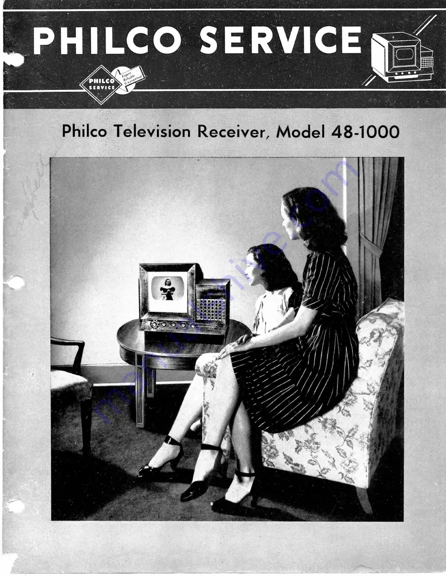
Page 1: ...PHILCO SERVICE SERVICE Phiico Television Receiver Model 48 1000 ...

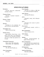
Page 2: ...egacycles Audio carrier 22 1 megacycles Operating Voltage 110 120 volts 60 cycles a c Power Consumption 275 watts Power Supplies 325 volts d c at 300 ma 7300 volts d c at 200 microamperes approx Audio Detector Ratio type FM detector A F C Automatic tuning with electronic control A V C J Automatic level control of picture and sound Tone Control Continuously variable treble to bass Bass Compensation...

Page 3: ...cause glare or reflections in the eyes of the audi ence It is advantageous to be able easily to darken the room somewhat for viewing ofday time programs The picture will appear clearer if the receiver is not placed near a window so that daylight will not be directly in back of or on either side of the picture screen Seating Space The picture can be viewed comfortably by most people from a distance...

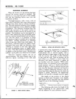
Page 4: ...st common type is the half wave dipole consisting of two rods each DIPOLE KIT HIGH FREQUENCY 45 1523 LOW FREQUENCY45 1525 AERIAL FROM KIT 45 1525 HOLES SHOWN IN PAIRS FOR CHANNEL NUMBERS AS SHOWN 1 2 3 4 5 6 ERIAL FROM KIT 45 1523 7 12 8 13 HOLES FOR CHANNEL 12 7 NUMBERS AS SHOWN 13 8 9 10 TP 2635 FIGURE 3 DIPOLE AND REFLECTOR AERIAL a quarter wave long separated by an insulating member See figure...

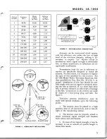
Page 5: ... lines for use in television re ception are specifically designed to match the antenna For this reason it is necessary to employ the type of line specified for the receiver For all 1948Model Philco Television Receivers 300 ohm parallel wire line Part No 45 1514 is re quired Installation of this line should be care fully made with special regard to properly secur ing the line at intervals of not mo...

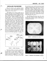
Page 6: ...ount ing when used with the High Frequency Aerial Kit and the Aerial Mast Kit Dipole and reflector lengths as supplied in the kits are chosen to provide a maximum of flexibility in reception of different channels with a minimum of cutting Further information and installation data for these antennas are supplied with each kit PREPARING THE RECEIVER FOR USE Whenever possible the receiver should be u...

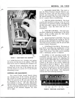
Page 7: ...et in the first position of clockwise rotation and adjusting the bass and treble response in the remainder of the rotation Turn this knob until the set is switched on 3 VOLUME CONTROL This knob oper ates R213 adjusting the amplificationof the audio signal It has no effect upon the video signal Adjust for desired volume 4 BACKGROUND CONTROL This knob operates R433 regulating the average d c bias of...

Page 8: ...ocated 13 WIDTH adjusts L503A and L503B regulating the amount of deflection current flow ing in the horizontal deflection coils thereby con trolling the horizontal dimension of the picture Adjust this control to obtain a picture wide enough to just fill the picture frame 14 VERTICAL CENTERING adjusts R524 controlling the amount and polarity of the d c centering current flowing in the vertical de f...

Page 9: ...compromise may be necessary aiming the antenna for the best average signal If separ ate low and high band antennas are used each antenna must be aimed separately See figure 10 CB3 O TP 2635 FIGURE 10 AIMING THE AERIAL The local oscillator coil trimmer should now be readjusted for each channel installed in the receiver and any other controls readjusted to t t obtain the best possible performance Th...

Page 10: ...l so that two as semblies comprise a set of coils for any one television broadcast channel Any eight of these thirteen sets of coils may be easily installed in the Philco Precision Channel Selector without soldering or wiring Since a maximum of only seven television broadcasting stations is alloted to any one area the Philco Precision Channel Selec tor is adaptable for use in any portion of the co...

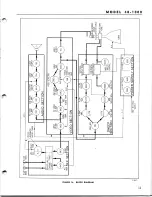
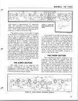
Page 11: ...O SECTION PHILCO MULTI CHANNEL TURRET TUNER VIDEO DETECTOR s 6AL5 1ST VIDEO If AMP 2ND VIDEO I F AMR A V C 1 DETECTOR 6A G5 ADJ AUDIO TRAP SIGNAL 7B6 STABILIZER A V C AMP MIXER R F SECTION VIDEO SECTION VERTICAL OUTPUT TRANS SWEEP SECTION HOR SWEEP GEN POWER SUPPLY SECTION BEAM BENDER COILS FOCUS COILS DEFLECTION YOKE 2 O o oo 115V 60 CYCLE SUPPLY ...

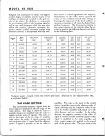
Page 12: ... 203 75 209 75 215 75 Local Osc Frequency me 71 85 81 85 87 85 93 85 103 85 109 85 201 85 207 85 213 85 219 85 225 85 231 85 237 85 Video I F me 26 6 26 6 26 6 26 6 26 6 26 6 26 6 26 6 26 6 26 6 26 6 26 6 26 6 Audio I F me 22 1 22 1 22 1 22 1 22 1 22 1 22 1 22 1 22 1 22 1 22 1 22 1 22 1 Adj Audio I F me none 32 1 28 1 28 1 32 1 28 1 none 28 1 28 1 28 1 28 1 28 1 28 1 Adjacent audio i f signal with...

Page 13: ...s an improved FM receiver consisting of two stages of audio i f amplification a discriminator one stage of audio amplification and an audio output stage driving a six inch permanent magnet speaker FIGURE 17 VIDEO SEC TION SCHEMATIC DIA GRAM TP 2665 H Incorporated in the FM discriminator circuit is a filter circuit connected to the center point of the discriminator output As long as the fre quency ...

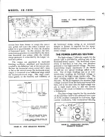
Page 14: ...E PRODUCES NO FURTHER DECREASE IN OUTPUT SIGNAL the horizontal sweep acting as an automatic damper or booster as required for the instan taneous conditions existing at any portion of the sweep voltage THE POWER SUPPLIES SECTION The high voltage 7 300 volt supply for the picture tube is provided by utilizing part of the horizontal sweep output The horizontal return sweep or kick back is very fast a...

Page 15: ... ma jor test points each section has key test points indicated by a letter within a black disc If an abnormal indication is obtained at a major test point the defective stage is isolated by testing at the key test points associated with the major test point The defective part then can be located by voltage and resistance measurements of the com ponents within the isolated stage Supplement ing the ...

Page 16: ...n 4 Video and Sec tion 5 Sweep TEST EQUIPMENT The following test equipment and parts are required to perform the trouble shooting tests by the test point method VTVM or 20 000 ohms per volt voltmeter with 10 000 volt multiplier OSCILLOSCOPE SIGNAL GENERATORS Generator A Audio signal generator Generator B FM signal generator Center frequency range 20 me to 30 me Sweep range 250 kc Generator C AM si...

Page 17: ...tage Low or high voltage POSSIBLE CAUSE OF ABNORMAL INDICATION Open R524 R525 L501 Shorted C103 Trouble not in this section DANGER HIGH VOLTAGE 7 sy High voltage anode supply 7300 volts d c No voltage Low voltage Defective 1B3GT Shorted C100 Horizontal sweep circuit Picture tube assembly Open C100 Defective or incorrect ly adjusted sweep FIGURE 22 BOTTOM VIEW SHOWING SECTION 1 TEST POINTS TP 2645 ...

Page 18: ... f 2 Z200 Generator B NORMAL INDICATION Loud clear audio out pu i Loud clear audio out put Loud clear audio out put Clear audio output not as loud as in step 3 Loud clear audio out put Loud clear audio out put Loud clear audio out pui POSSIBLE CAUSE OF ABNORMAL INDICATION Trouble in this section Defective speaker T200 C222 7B5tube Open C221A Open C223 R218 Defective 7B4 tube Shorted C214 C215 C213...

Page 19: ... 20 000 ohms per volt meter Use 1000 ohm resistor in series with nega tive lead of 20 000 ohms per voltmeter STEP 1 TEST POINT j y Loose couple to V 4 antenna at J300 Generator C NORMAL INDICATION Loud clear audio output ABNORMAL INDICATION Weak or no out put POSSIBLE CAUSE OF ABNORMAL INDICATION Trouble in this section proceed to step 2 FIGURE 24 BOTTOM VIEW SHOWING SECTION 3 TEST POINTS TP 2665 ...

Page 20: ...ible on picture tube Set the CONTRAST control fully clockwise Generator A Audio signal generator Use a 1 mf condenser in series with signal lead Generator D AM signal generator set to 26 6 me STEP 1 2 3 4 5 6 TEST POINT y Couple to plate ofmixer W pin5 Generator D M Plate of 7C5 video out put pin 2 Generator A D Grid of 7C5 pin 6 Generator A A Grid of 6AG5 video amplifier pin 1 Generator A D Plate...

Page 21: ... Generator D NORMAL INDICATION Same as step 2 Same as step 2 Same as step 2 POSSIBLE CAUSE OF ABNORMAL INDICATION Defective 6AG5 1st video i f tube Z402 Open R409 R410 L405 R408 Shorted C409 C427 C408 Defective GAGS input i f tube Z401 Open R200 R406 R405 L404 Shorted C406 C203 Defective Z400 Illlli HORI2 VERT HOLD HOLD FIGURE 25 BOTTOM VIEW SHOWING SECTION 4 TEST POINTS TP 2665 E 21 ...

Page 22: ...horizontal sweep circuit pro Horizontal sweep at yoke pin 1 of J500 through 15 000 ohm re sistor Replace 6SL7GT hor sweep gen Re move 6SL7GT vertical sweep gen ceed to step 7 3 volts Pin 4 of 6SL7GT vert sweep gen 6SL7GT in socket Defective 6SL7GT tube T500 Open R517 R518 R510 R511 Shorted C505 C506A C507 C504 240 volts Pin 2 of 6SL7GT vert sweep gen Open R516 R515 R514 R513 R512 Shorted C506B C50...

Page 23: ...M O D E L 4 8 1 0 0 0 FIGURE 26 BOTTOM VIEW SHOWING SECTION 5 TEST POINTS TP 2665 F 23 ...

Page 24: ... step 12 10 volts 12 13 14 15 16 17 Pin 6 of GAGS video arnpl Trouble in Section 4 Refer to Section 4 trouble shooting procedure 10 volts Pin 6 of sync sep Open C500 R547 Shorted C500 8 volts JTk Pin 8 of 7F8 sync ampl Defective 7B5 sync sep tube Open R503 R502 R504 C502 R548 C506 Shorted C502 C501 1 volt Same as step 11 Same as step 11 Defective 7F8 tube Open C504 R508 R509 R507 Shorted C503 Junc...

Page 25: ... SECTION 3 RF 25 ...

Page 26: ... SECTION 2 AUDIO SECTION 5 SWEEP 26 FIGURE 27 PHILCO TELEVISION RECEIVER MODEL 48 1000 COMPLETE SECTIONALIZED SCHEMATIC DIAGRAM ...

Page 27: ...SECTION 4 VIDEO 4 5 MC TRAP SECTION 1 POWER SUPPLY AM TP 2665 27 ...

Page 28: ...er while the receiver is turned on The yoke plug acts as an interlock which disconnects the primary supply of the re ceiver if the plug is not connected If it is neces sary for special purposes to operate the receiver without the speaker and the picture tubeassembly remove the vertical and horizontal sweep gener ator tubes and the audio output tube before turn ing the receiver on TEST EQUIPMENT Sp...

Page 29: ...ncy 22 1 me devia tion 1 me Use generator B to set generator A to exact center frequency Set to 197 75 me mod ulation off Set receiver channel selector to channel No 10 OUTPUT INDICATOR CONNECTION Oscilloscope vertical in put to J401 horizontal input to generator A sweep output Same as step 2 Same as step 2 Same as step 2 Same as step 2 Voltmeter between pin 7 of 6AL5 discriminator and chassis Sam...

Page 30: ...olts Connect calibrated oscilloscope to J401 and ad just a v c see figure 29 to obtain a 2 volt peak to peak reading on oscilloscope If the available generator is not capable of 100 modulation but the modulation percentage is known check by trapezoid method set the a v c to the same percentage of the 2 volt reading LOC OSC ADJ L300A THRU THIS HOLE TP 2758 FIGURE 29 TOP VIEW OF CHASSIS AVC ADJUSTME...

Page 31: ...0 UJ a UJ ac 100 80 R 40 20 0 2 2 22 i 6 vie 1 vtC 1 3 n 7J M C 2 4 25 rfc 4 6 S M N c s s K 1 S 5 s 7 SJ M V C 2 2 6 6 0 M s V1 TP 2638 TP 2639 FIGURE 30 VIDEO I F CURVES FIGURE 31 VIDEO I F CURVES 5 21 35Me 21 BSMc 22 1Mc 22 35Mc FREQUENCY 22 B5Mo DISCRIMINATOR CHARACTERISTIC SWEEP GENERATOR FED INTO INPUT F STAGE FIGURE 32 DISCRIMINATOR CHARACTERISTIC CURVE TP 2640 31 ...

Page 32: ...riminator secondary Part of Z202 Filament choke 32 4112 3 Discriminator bal choke 32 4143 1 Plate filter 66 2333340 Grid resist 66 4223340 Cathode resist 66 0683350 Symbol R203 R204 R205 R206 R207 R208 R209 R210 R211 R212 R213 R214 R215 R216 R217 R218 R219 R220 R221 T200 Z200 Z201 Z202 C301A C301B C302 C303 C304 C305 C306 C307 C308 C309 C310 C311 C312 C313 C314 C315 Value 47 000 ohms 3300 ohms 220...

Page 33: ...deo output screen by pass Part of C422 Video output plate filter Part of C422 Plate blocking 61 0122 CRT cathode blocking cond 45 3500 4 Symbol C425 C426 C427 C428 C429 J400 J401 L400A L400B L401A L401B L401C L402A L402B L402C L403A L403B L404 L405 L406 L407 L408 L409 L410 L411 R400A R400B Value 05 mf 004 mf 10 mmf 10 mmf 22 mmf 150 microhenries 70 microhenries 40 microhenries 10 000 ohms 10 000 o...

Page 34: ...put Part of C506 C507 1 mf By pass condenser vert hold 61 0113 C508 1 mf High pass filter plate vert sweep gen 61 0113 C509 25 mf Coupling condenser vertical output 61 0125 C510 10 ml electrolytic Plate filter vertical output 30 2417 6 Symbol Value C511 100 mmf C512 05 mf C513 001 mf C514 Service Part No 820 mmf 820 mmf 01 mf 1 mf 47 mmf 02 mf 50 mf electrolytic Function Coupling condenser hor syn...

Page 35: ...03340 Cathode bias hor output 66 1105340 Screen filter hor output 66 2395340 Grid leak hor damping 66 4103340 HOR LIN control grid leak hor damping 33 5539 13 Suppressor hor damping 66 2473340 High freq filter hor damping 66 4103340 Suppressor hor damping 66 2473340 Symbol R544 R545 R546 SECTION 5 Continued Service Value Function Part No 10 ohms HOR CENT control 33 5546 R547 22 000 ohms 10 000 ohm...

Page 36: ...8340 66 3228540 66 5103340 66 4108540 66 0688340 66 1108340 66 4108540 66 2108540 Channel 1 osc turret coil part no 32 4128 1 and antenna turret coil part no 32 4115 1 are not yet available because Channel 1 has not been released for commercial broadcasting SECTION 4 C414 should be part no 61 0120 C416 should be part no 61 0120 R405 should be part no 66 0683340 R408 should be part no 66 0683340 R4...

Page 37: ... 105340 30 2417 6 66 4228540 66 0683350 66 1158310 62 147001001 REASON To allow test signal input at J401 To reduce oscillation To reduce oscillation Not needed with Iriode out put Not needed with triode out put To prevent molorboating on high channels To preveti I motorboaling on high channels To reduce operating tem perature of C102 To improve a i f response To improve a i f response To improve ...

Page 38: ... 7 9 L504 added 26 Condensers C223 added 6 C514A rewired 20 C515 changed 21 C5J 6 changed 22 C517 rewired 23 C523 added 34 C524 added 35 Controls L503 changed 4 7 9 B532 changed 14 Horizontal Hold Control B532 changed 14 Discriminator L205 added i Z202 changed 5 Resistors R528 rewired 10 R529 changed 11 R530 changed 12 R531 changed 13 R532 changed 14 R533 changed 15 R549 changed 16 R550 added 17 R...

Page 39: ...27 19 27 19 26 27 19 26 27 19 26 27 19 26 27 19 26 27 19 26 27 19 26 27 19 26 27 19 26 27 19 26 27 19 26 27 19 26 27 19 26 27 19 26 27 19 26 27 19 26 27 19 26 27 19 26 27 19 26 27 CHANGE EFFECTIVE Run 82 Run 82 Run 2 Run 3 Run 4 Run 4 Run 85 Run 85 Run 86 Run 7 Run 7 Run 7 Run 7 Run 7 Run 7 Run 7 Run 1 Run 87 Run 7 Run 7 Run 87 Run 87 Run 7 Run 87 Run 87 Run 87 Run 87 Run 87 NEW OR ADDED PART NO 3...

Reviews: