
Published by CO 0070 Service PaCE
Printed in the Netherlands
Subject to modification
5
3122 785 10850
©
Copyright 2000 Philips Consumer Electronics B.V. Eindhoven, The Netherlands.
All rights reserved. No part of this publication may be reproduced, stored in a
retrieval system or transmitted, in any form or by any means, electronic, mechanical,
photocopying, or otherwise without the prior permission of Philips.
Colour Television
Chassis
EM1A
AA
CL 06532111_000.eps
171000
Contents
Page
Contents
Page
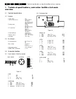
1.
Technical specifications, connection facilities &
chassis overview
2
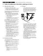
2.
Safety- and maintenance instructions,
4
warnings and notes.
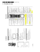
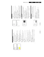
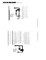
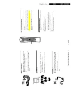
3.
Directions for use
6
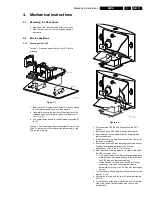
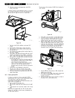
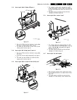
4.
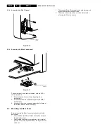
Mechanical instructions
11
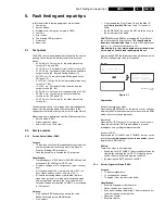
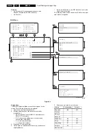
5.
Faultfinding and repair tips
15
6.
Block-, wiring diagrams and testpoint overviews
Blockdiagram video processing
27
Blockdiagram audio & control
28
Blockdiagram Large Signal Panel: supply
29
Powerlines overview
30
Wiring diagram
31
I
2
C overview
32
Testpoint overview LSP
33
Testpoint overview SSB / DW / CRT panel
34
7.
Electrical diagram’s en PWB’s
Diagram PWB
Main supply
(Diagram A1) 35
43-48
Standby supply
(Diagram A2) 36
43-48
Line deflection
(Diagram A3) 37
43-48
Frame deflection
(Diagram A4) 38
43-48
Audio amplifier
(Diagram A5) 39
43-48
Headphone amplifier
(Diagram A6) 40
43-48
Tuner, I/O, SIMM-connector
(Diagram A7) 41
43-48
Front control
(Diagram A8) 42
43-48
SSB: SIMM-connector
(Diagram B1) 49
55-60
IF, I/O, videoprocessing
(Diagram B2) 50
55-60
Feature box
(Diagram B3) 51
55-60
HOP
(Diagram B4) 52
55-60
Audio demodulator
(Diagram B6) 53
55-60
Painter
(Diagram B7) 54
55-60
Multi PIP controller
(Diagram C1) 61
65/66
Tuner
(Diagram C2) 62
65/66
I/O processing
(Diagram C3) 63
65/66
IF video sync
(Diagram C4) 64
65/66
Side I/O panel
(Diagram D)
67
67
Top control panel
(Diagram E)
69
69
CRT panel
(Diagram F)
70
71
DC-shift panel
(Diagram G)
71
71
Horizontal DAF panel
(Diagram I1)
72
74
Vertical DAF panel
(Diagram I2)
73
74
Mains switch panel
(Diagram J)
75
75
Mains harmonic panel
(Diagram Y)
76
76
8.
Alignments
77
9.
Circuit description and
82
list of abbreviations
96
10. Spareparts list
98


