Published by WO 0365 Service PaCE
Printed in the Netherlands
Subject to modification
EN 3122 785 13100
©
Copyright 2003 Philips Consumer Electronics B.V. Eindhoven, The Netherlands.
All rights reserved. No part of this publication may be reproduced, stored in a
retrieval system or transmitted, in any form or by any means, electronic,
mechanical, photocopying, or otherwise without the prior permission of Philips.
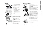
Colour Television
Chassis
EM6E
AB
For DVD module use Service Manual DVD SD5.31SL (3122 785 13710)
CL 36532008_156.eps
130603
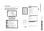
Contents
Page
Contents
Page
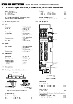
1.
Technical Specifications and Chassis overview 2
2.
Safety & Maintenance Instr., Warn., and Notes 5
3.
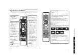
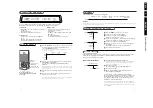
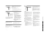
Directions for Use
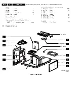
4.
Mechanical Instructions
5.
Service Modes, Error Codes and Faultfinding
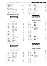
6.
Block Diagram, Testpoints, and Overviews
Wiring Diagram
Block Diagram Supply and Deflection
Testpoint Overv. LSP, Auto SCAVEM, and CRT 43
Block Diagram Video
Testpoint Overview Small Signal Board
Block Diagram Audio
Block Diagram Controls
I2C IC’s overview
Supply Lines Overview
Block Diagram Wireless Kit
7.
Electrical Diagrams and PWB’s
Diagram PWB
LSP: Main Supply
(Diagram A1)
59-64
LSP: Stand-by Supply
(Diagram A2)
59-64
LSP: Line Deflection
(Diagram A3)
59-64
LSP: Frame Deflection E/W Drive(Diagr. A4)
59-64
LSP: Rotation Circuitry
(Diagram A5)
59-64
LSP: Audio Amplifier
(Diagram A6)
59-64
LSP: Small Signal Part
(Diagram A8)
59-64
LSP: Front
(Diagram A9)
59-64
SSB: Connector
(Diagram B1)
86-99
SSB: IF, I/O Video Processing (Diagram B2)
86-99
SSB: PICNIC (Feature Box)
(Diagram B3A)
86-99
SSB: Falconic
(Diagram B3B)
86-99
SSB: Eagle
(Diagram B3C) 70
86-99
SSB: HOP
(Diagram B4)
86-99
SSB: OTC Flash
(Diagram B5A)
86-99
SSB: Anti-moiré
(Diagram B5B)
86-99
SSB: OTC Flash
(Diagram B5C) 73
86-99
SSB: Audio Demodulator
(Diagram B6A)
86-99
SSB: Dolby Digital Decoder
(Diagram B6B)
86-99
SSB: Dolby Prologic Processor (Diagram B6C) 76
86-99
SSB: DC/DC-Convertor
(Diagram B12)
86-99
SSB: Tun1/Tun2
(Diagram B13)
86-99
SSB: I/O Eur
(Diagram B14A) 79
86-99
SSB: I/O Eur
(Diagram B14B) 80
86-99
SSB: 2FH I/O
(Diagram B14C) 81
86-99
SSB: Audio I/O
(Diagram B14D) 82
86-99
SSB: PIP-HIP
(Diagram B15A) 83
86-99
SSB: PIP-I/O
(Diagram B15B) 84
86-99
SSB: PIP (Muppet)
(Diagram B15C) 85
86-99
Mains Switch Panel
(Diagram E)
101
CRT Panel
(Diagram F1)
104-105
CRT/ Auto SCAVEM Panel
(Diagram F2)
104-105
DC Shift Panel
(Diagram G)
VDAF Panel + 2nd Orders
(Diagram I)
108
Eject Button
(Diagram K
LCD Board
(Diagram L
111
Side I/O Panel
(Diagram O)
112
113
Top Control Panel
(Diagram P)
Wireless Transmitter
(Diagram R)
116-117
Top Control Panel
(Diagram P)
Radio ECO6 3 Band Cenelec (Diagram RAD) 118
119
Wireless Receiver/Front-end
(Diagram S1)
122
Wireless Receiver/Back-end
(Diagram S2)
123
Auto SCAVEM Panel
(Diagram SC1) 124
125
Interface Board
(Diagram T1-T4) 126-129 130
Audio Output Amplifier
(Diagram W)
132-133
8.
Alignments
9.
Circuit Description
10 Spare Parts List
11 Revision List
194