background image

Real Time  Digital Video  Recorders

Philips
Communication,
Security & Imaging

Installation Instructions

EN

Summary of Contents for Hi-Q

Page 1: ...Real Time Digital Video Recorders Philips Communication Security Imaging Installation Instructions EN ...

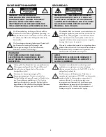
Page 2: ...it 17 Servicing Do not attempt to service this unit yourself as opening or removing covers may expose you to dangerous voltage or other hazards Refer all servicing to qualified service personnel 18 Damage Requiring Service Unplug the unit from the outlet and refer servicing to qualified service personnel under the following conditions a When the power supply cord or plug is damaged b If liquid has...

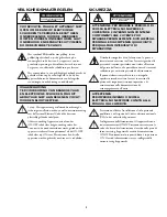
Page 3: ...tion locale pertinente Disjonction de l alimentation Les appareils avec ou sans commutateurs ON OFF sont alimentés à chaque fois que le cordon d alimentation est branché à la source d alimentation toutefois les appareils disposant de commutateurs ON OFF ne fonctionnent que lorsque le commutateur ON OFF est dans la position ON Le cordon d alimentation constitue le moyen de disjonction de l alimenta...

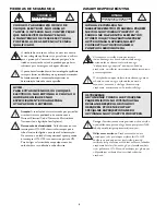
Page 4: ...l punto de exclamación dentro de un triángulo equilátero pretende alertar al usuario de la existencia de instrucciones de funcionamiento y mantenimiento reparación en la documentación suministrada con el aparato Atención La instalación debe realizarla personal cualificado en cumplimiento estricto del código eléctrico nacional en el caso de los EE UU o de los códigos locales aplicables Para Descone...

Page 5: ...angolo equilatero intende avvisare l utente in merito alla presenza di importanti istruzioni operative e di manutenzione nella documentazione di accompagnamento all unità Precauzione affidare l installazione al solo personale qualificato e nel rispetto del Codice elettrico nazionale USA o dei codici locali pertinenti Scollegamento dell alimentazione Gli apparecchi con o senza commutatori ON OFF ri...

Page 6: ...ICOS NÃO EXPONHA À CHUVA OU HUMIDADE UNIDADES NÃO ESPECIFICAMENTE CRIADAS PARA UTILIZAÇÃO NO EXTERIOR ZASADY BEZPIECZEŃSTWA Błyskawica ze strzałką wewnątrz trójkąta równobocznego ma za zadanie zwrócić uwagę użytkownika na obecność nieizolowanego niebezpiecznego napięcia wewnątrz obudowy urządzenia o wielkości stwarzającej niebezpieczeństwo porażenia prądem Wykrzyknik wewnątrz trójkąta równoboczneg...

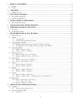
Page 7: ...t Calendar 17 7 4 Configuring Alarms 18 7 4 1 Submenu Alarms Inputs 19 7 4 2 Submenu Alarms Outputs 19 7 5 Motion Detection 19 7 5 1 Submenu Motion Detection Settings 20 7 5 2 Submenu Motion Detection Active Zones 20 7 6 Data Storage 21 7 6 1 Submenu Data Storage Hard Drive 21 7 6 2 Submenu Data Storage Archive 21 7 7 System 21 7 7 1 Submenu System Password 21 7 7 2 Submenu System Network 21 7 8 D...

Page 8: ...erature Monitoring 30 12 REPLACEMENT PARTS 30 13 Hi Q MANAGEMENT UTILITY 31 13 1 Overview 31 13 2 Operating System Requirements 31 13 3 Installation 31 13 4 Hi Q Management Utility Operations 31 13 4 1 Hi Q Version Information 32 13 4 2 Bosch Security Systems Inc Software Update Site 32 13 4 3 Transferring Files 32 13 4 3 1 File Selection Controls 32 13 4 3 2 File Transfers 32 14 TROUBLESHOOTING 3...

Page 9: ...chiving Authentication Management Utility software Compatible with Philips DVAD and DVAS Series Disk Arrays 19 inch rack mountable 2 UNPACKING Unpack carefully to prevent damage to the equipment 2 1 Package Contents Check for the following items Philips DVRRT4 or DVRRT4EP unit Mounting Ears for a 19 inch rack Part 303 3638 001 Use Rack Mount Kit 303 3740 501 see Appendix E for instructions Screw T...

Page 10: ...playback speed adjustment outside shuttle ring 8 Power LED Indicates that the system has power 9 Alarm List Displays alarm list newest first LED is lit when there are noncleared alarms 10 Alarm Clear Acknowledges all active alarms silences beeper stops flashing alarm icons on MON A and ends sequencing of alarm video on MON B Resets active relays to nonalarm state 11 1 Touch Alarm Triggers alarm re...

Page 11: ...Z cameras Screw terminal 4 Keyboard loop through and keyboard input RJ 11 5 MON A and B outputs BNC 6 4 video inputs 75 Ω autoterminating BNC 7 4 video looping ports 75 Ω autoterminating BNC 8 AUDIO OUT Screw terminal 9 4 RELAY outputs N O or N C Screw terminal 10 Auto sensing power input 110 220 VAC 50 60 Hz IEC male 11 CONSOLE RS 232 CCL port DB 9 male 12 Ethernet status lights 13 Ethernet 10 10...

Page 12: ...AMERA 1 MONITOR LOOP KEYBD B 2 3 4 AUDIO IN AUDIO OUT ALARM IN RELAY SDA CONSOLE RX TX COL 100 ETHERNET SCSI S S 1 S 2 S 3 S 4 0 1 2 3 4 S S S S A 2 conductor Shielded Cable S S To Balanced Audio Device S Audio In Audio Out NOTE Balanced connections are more immune to noise used for longer distances S 1 conductor Shielded Cable To Unbalanced Audio Device Audio In Audio Out S S NOTE Unbalanced conn...

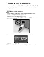
Page 13: ...n NOTES By default audio recording is disabled to prevent unintentional audio recording that could violate legal restrictions The administrator must enable the audio feature if desired Audio recording occurs only if Channel 1 is recording video 4 Attach a monitor to MON A for viewing Hi Q configuration menus 5 Locate the in line surge protector packaged with the Hi Q and install it between the Hi ...

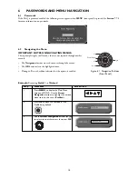
Page 14: ...hrough the menus The OK button selects the highlighted item Placing an X in a checkbox indicates that the option is enabled Example Renaming Profile 1 to Weekend Step Procedure Screen Icon 1 Press MENU to display the Main Menu Screen on MON A Use the Arrow Navigation buttons to highlight the desired menu item in this case Profiles 2 Press OK to open the text box of the Profile being defined 3 Use ...

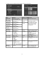
Page 15: ...ng a Profile The profile manager allows the user to name a profile optional 12 characters maximum copy its contents or reset it to default To edit a profile name select menu option Profiles Manager 7 2 2 Configuring Recording Quality and Alarms 1 Select the profile to be edited via Profiles Edit Profile 15 Menu Title Submenu 1 Submenu 2 Calendar Settings Edit Calendar Profiles Manager Edit Profile...

Page 16: ...r Disabled alarm inputs Relay Output Each channel Disabled If enabled an alarm on the channel Enabled or Disabled triggers a relay output response Record Video Each channel Continuous Defines type of recording for Continuous each channel Event Only Event Only records pre alarm Do Not Record video for the pre alarm time see Section 7 4 1 Record Audio Camera 1 only Disabled Audio available on Channe...

Page 17: ...to the 7 day calendar profiles 7 3 1 Enabling and Viewing the Calendar Submenu Calendar Settings 7 3 2 Inserting Profiles into the Calendar Submenu Calendar Edit Calendar 17 Field Values Default Value Explanation Calendar Enabled Disabled If disabled all active channels Disabled use Profile 1 all of the time Override The text screen below appears for selection of values Text Box Values Default Val...

Page 18: ...ormat in 15 minute intervals Stop Time 24 hour time format in 15 minute intervals Days Days to be scheduled for this profile Profile Profile to be scheduled Select Enter Scroll down to view the 7 day calendar containing all programmed profiles 7 4 Configuring Alarms Alarm configuration estalishes alarm polarity beeper dwell time and global pre alarm and post alarm settings 18 ...

Page 19: ...AULT VALUE Auxiliary Alarm Input Polarity Normally Open Normally Open Cameras 1 4 individually Normally Closed Auxiliary Alarm Recording Enabled Disabled Follows Contact Disabled Pre alarm Time 1 to 60 seconds 30 seconds Post alarm Time Video Motion 1 to 60 minutes 1 minute Video Dark Auxiliary 1 Touch FIELD VALUES DEFAULT VALUE Warning Beep Enabled Enabled Disabled Relay Output Polarity Normally ...

Page 20: ...and saves settings Cancel Exits screen without saving settings 20 FIELD VALUES DEFAULT VALUE EXPLAINED Suppression Standard Standard Standard ignores small lighting Stable changes less than 25 None Stable ignores large lighting changes less than 50 None responds to all changes recommended for indoor applications Target Size 1 h x 1 v 2 h x 2 v Defines size of motion grid horizontally 1 h x 2 v by ...

Page 21: ...o be used on the network See Appendix D for Hi Q on screen character set XXXX is the last 4 digits of the Hi Q recorder serial number 21 FIELD VALUES DEFAULT VALUE Disk Full Behavior Overwrite Overwrite Stop Recording Stop Recording is the default non adjustable if a disk array is recognized Disk 1 Status Good Calculated Bad Disk 2 Status Good Calculated Bad Not Installed Total Capacity Hard disk ...

Page 22: ...Regional 22 FIELD VALUES DEFAULT VALUE Camera Titles text entry max Camera 1 2 3 4 Cameras 1 4 individually 12 characters Dwell Time 1 to 60 seconds 3 Monitor A 1 second increments Monitor B Brightness manual gain Automatic enabled or disabled AUTO for MON A only Values 50 to 50 Cameras 1 4 individually REGIONAL FIELD VALUES DEFAULT VALUE Language English English German French Italian Spanish Dutc...

Page 23: ...the time frame in the screen as below Available Actions View Log displays the Search Results submenu Cancel stops the search 7 10 1 1 Contents of Activity Log Error and warning messages Alarms Alarm clear and alarm review actions Setup changes Video Clip Archive Requests Power cycle messages Administrator log in log out Archive tape change 7 10 2 Submenu Information Help Displays helpful descripti...

Page 24: ...not delete it from hard drive Play Plays selected alarm video internal hard drive only To stop playback press STOP Press STOP again to exit to live video Archive Displays the archive screen see Section 10 for archiving details If the Hi Q is programmed for Continuous archive this option is disabled Clear All Permanently deletes all items in the alarm list at exit Cancel Removes the Pop up menu fro...

Page 25: ... Quad view audio playback and frame advance are disabled Live video in quad mode appears to be time lapsing even though video may be recorded in real time 9 3 Playback Search To search for recorded video based on time date camera or alarm type press PLAY during live mode Search Procedure 1 Press PLAY to present the Playback Search screen 2 Enter search criteria 3 Select Search Archive or Disk NOTE...

Page 26: ...e for faster retrieval If the search screen is exited or the tape is ejected its indices are purged from the system so be sure that the current search is complete before exiting While in playback mode press STOP to revert to the previous Playback Search screen Press STOP again to exit and return to live mode Playback Search Results Options Play The selected alarm video is played Archive The archiv...

Page 27: ...d show the archive device type 10 2 Connecting to Disk Array Device 1 With all power disconnected connect the appropriate SCSI cable from the disk array to the Hi Q 2 Power the disk array and wait for it to initialize approximately 1 minute see Disk Array Instruction Manual 3 Apply Power to the Hi Q 4 Ensure proper communication between the two devices via the Hi Q menu Data Storage Archive the sc...

Page 28: ...ttings NOTE Event Only and Manual Archive modes are only applicable for tape devices If Archive Mode is set to Continuous or Event Only recording stops when it s about to overwrite video identified for archival A message is displayed when the unit stops recording Resume recording by selecting the menu option Data Storage Hard Drive RECORD Event Only archiving is a global setting an alarm on any ca...

Page 29: ...me is dependent upon the type of archiving Event Only archive tapes typically take longer How can a tape be protected so that it is not mistakenly overwritten Depress the tape s write protect tab Why won t the tape eject If the tape drive is busy or reading writing data the eject button is disabled Either wait for the tape drive to complete its task or use the Hi Q s menu option Eject see Section ...

Page 30: ...EPLACEMENT PARTS Part No Description 303 3638 001 Mounting Ears for a 19 inch rack Use Rack Mount Kit 303 3740 501 303 2143 001 Power Cord 120 V 303 0167 002 Power Cord 240 V 303 0588 001 Hi Q Battery Rayovac battery lithium 3 V 180 mAH button cel type part BR2325 B 303 1759 003 3 pin Screw Terminal Connector 303 1759 008 8 pin Screw Terminal Connector 303 1759 012 12 pin Screw Terminal Connector ...

Page 31: ...ws NT 4 0 with Service Pack 6 and Windows 2000 and it must be configured with TCP IP network protocol The Hi Q Management Utility s user interface is supported under the Danish Dutch English Finnish French German Italian Norwegian Portuguese Spanish and Swedish localized versions of the operating systems listed above but is displayed in English only 13 3 Installation Exit all Windows programs prio...

Page 32: ...settings etc System Activity Logs log a list of Hi Q activities and operations 13 4 3 1 File Selection Controls Select each file to be transferred between the Hi Q and Hi Q Management Utility by choosing the appropriate option A file is only transferred between the Hi Q and Hi Q Management Utility if its corresponding checkbox has been set Setting a checkbox enables un grays the file s controls Fi...

Page 33: ...ity Systems Technical Support for password reset instructions Hi Q Management Utility Wrong network connection Program proper IP address can t access Hi Q into the Hi Q Cannot view Quad screen Ensure MON A LED is lit Press Monitor ensure the A on MON A LED is lit then press Quad Hi Q Recorder Splash screen Verify input AC voltage is within If necessary to maintain a periodically flashes on MON A t...

Page 34: ...rk Interface Hi Q Management Utility Software upgrades saving recording profiles and log files to PC The Hi Q Management Utility runs under Windows 98 ME Windows NT with Service Pack 6 and Windows 2000 must be configured with TCP IP network protocol Mechanical Dimensions 441 96 W x 464 8 D x 137 16 H mm 17 4 W x 18 3 D x 5 4 H in Weight 10 94 kg 24 1 lb Temperature 10 to 45 C 50 to 113 F Relative ...

Page 35: ...rray Hard Drive Data Redundancy For DVRRT4EP Model Only Striping Disk 1 2 Status Determined by System Total Disk Capacity Calculated Archive Mode Manual set to Stop Recording with disk array Motion Detector Setup Target Size 2 h x 2 v Motion Zones All Grid Elements Active Sensitivity 70 Suppression Standard Motion Detector Direction All 1 Target Speed 0 40 seconds Miscellaneous Setups Profile Name...

Page 36: ...pplied Rack Mount Kit quantity 2 Rack mount ears 6 Phillips pan head screws with integral lock washers Mounting 1 Remove the 6 flat head screws located near the front panel on the right and left side of the housing and discard 2 Attach the mounting ears to each side using the 6 supplied Phillips pan head screws with lock washers and tighten securely 3 Install the unit into the rack using the Rack ...

Reviews: