background image

Published by TY 0872 BU TV Consumer Care

Printed in the Netherlands

Subject to modification

EN 3122 785 18171

©

Copyright 2008 Koninklijke Philips Electronics N.V.

All rights reserved. No part of this publication may be reproduced, stored in a 
retrieval system or transmitted, in any form or by any means, electronic, 
mechanical, photocopying, or otherwise without the prior permission of Philips.

Colour Television

Chassis

LC8.1E

LB

I_1

8

170_000.ep

s

3

0070

8

MG

8

MG

8

Contents

Page

Contents

Page

1.

Technical Specifications, Connections, and Chassis 
Overview

2

2.

Safety Instructions, Warnings, and Notes

5

3.

Directions for Use

6

4.

Mechanical Instructions

7

5.

Service Modes, Error Codes, and Fault Finding 12

6.

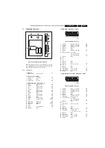
Block Diagrams, Test Point Overview, and 
Waveforms

Wiring Diagram 32" (MG8)

23

Wiring Diagram 42" (MG8)

24

Block Diagram Video

25

Block Diagram Audio

26

Block Diagram Control & Clock Signals

27

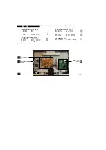
SSB: Test Points (Overview Bottom Side)

28-30

I2C IC Overview

31

Supply Lines Overview

32

7.

Circuit Diagrams and PWB Layouts

Diagram PWB

SSB: DC/DC

(B01) 33

47-51

SSB: Tuner IF & SAWF

(B02) 34

47-51

SSB: Micro Processor NVM

(B03) 35

47-51

SSB: TDA154XX

(B04A) 36

47-51

SSB: DDR Flash Trap

(B04B) 37

47-51

SSB: LVDS Connectors

(B04C) 38

47-51

SSB: SMIC L

(B05A) 39

47-51

SSB: Audio Class D

(B05B) 40

47-51

SSB: YPBPR & SVHS

(B06A) 41

47-51

SSB: IO Scart 1

(B06B) 42

47-51

SSB: Scart2 & UART & JTAG

(B06C) 43

47-51

SSB: HDMI

(B06D) 44

47-51

SSB: SRP List Explanation

45

SSB: SRP List

46

Keyboard Control Panel

(E) 52

52

IR & LED Panel

(J) 53

54

8.

Alignments

55

9.

Circuit Descriptions, Abbreviation List, and IC Data 
Sheets

58

Abbreviation List

63

IC Data Sheets

65

10. Spare Parts List & CTN Overview

71

11. Revision List

71

Summary of Contents for LC8.1E

Page 1: ...verview and Waveforms Wiring Diagram 32 MG8 23 Wiring Diagram 42 MG8 24 Block Diagram Video 25 Block Diagram Audio 26 Block Diagram Control Clock Signals 27 SSB Test Points Overview Bottom Side 28 30 I2C IC Overview 31 Supply Lines Overview 32 7 Circuit Diagrams and PWB Layouts Diagram PWB SSB DC DC B01 33 47 51 SSB Tuner IF SAWF B02 34 47 51 SSB Micro Processor NVM B03 35 47 51 SSB TDA154XX B04A ...

Page 2: ...angle HxV degrees 176 176 Tuning system PLL Presets channels 99 presets Tuner bands VHF UHF S H TV Colour systems PAL B G D K I SECAM B G D K L L Video playback NTSC PAL SECAM Supported computer formats 640 480 720 480 800 600 1024 768 1280 720 Supported video formats 480i 60 Hz 480p 60 Hz 576i 50 Hz 576p 50 Hz 720p 50 60 Hz 1080i 50 60 Hz 1080p 24 25 30 50 60 Hz 1 1 2 Sound Sound systems Nicam St...

Page 3: ...MS 10 kohm j 3 Audio L 0 5 VRMS 1 kohm k 4 Ground Gnd H 5 Ground Gnd H 6 Audio L 0 5 VRMS 10 kohm j 7 n c 8 Function Select 0 2 V INT 4 5 7 V EXT 16 9 9 5 12 V EXT 4 3 j 9 Ground Gnd H 10 n c 11 n c 12 n c 13 Ground Gnd H 14 Ground Gnd H 15 Video C 0 7 VPP 75 ohm j 16 n c 17 Ground Gnd H 18 Ground Gnd H 19 Video CVBS 1 VPP 75 ohm k 20 Video CVBS 1 VPP 75 ohm j 21 Shield Gnd H 5 EXT1 Video RGB In C...

Page 4: ...q Wh Audio L 0 5 VRMS 10 kohm jq Rd Audio R 0 5 VRMS 10 kohm jq 9 Cinch Video YPbPr In Audio In Gn Video Y 1 VPP 75 ohm jq Bu Video Pb 0 7 VPP 75 ohm jq Rd Video Pr 0 7 VPP 75 ohm jq Wh Audio L 0 5 VRMS 10 kohm jq Rd Audio R 0 5 VRMS 10 kohm jq 10 Head phone Out Bk Head phone 32 600 ohm 10 mW rt 1 3 Chassis Overview Figure 1 4 PWB CBA locations I_18170_028 eps 310708 B MAIN POWER SUPPLY PANEL SMAL...

Page 5: ... waveforms and voltages with D and without E aerial signal Measure the voltages in the power supply section both in normal operation G and in stand by F These values are indicated by means of the appropriate symbols 2 3 2 Schematic Notes All resistor values are in ohms and the value multiplier is often used to indicate the decimal point location e g 2K2 indicates 2 2 kΩ Resistor values with no mul...

Page 6: ... number Digits 1 and 2 refer to the production center e g AG is Bruges digit 3 refers to the B O M code digit 4 refers to the Service version change code digits 5 and 6 refer to the production year and digits 7 and 8 refer to production week in example below it is 2006 week 17 The 6 last digits contain the serial number Figure 2 1 Serial number example 2 3 6 Board Level Repair BLR or Component Lev...

Page 7: ...chapter 4 1 Cable Dressing 4 2 Service Positions 4 3 Assy Panel Removal MG8 Styling 4 4 Set Re assembly Notes Figures below can deviate slightly from the actual situation due to the different set executions 4 1 Cable Dressing Figure 4 1 Cable dressing 32 sets I_18170_029 eps 310708 ...

Page 8: ... for all types and sizes of Flat TVs See figure Foam bars for details Sets with a display of 42 and larger require four foam bars 1 Ensure that the foam bars are always supporting the cabinet and never only the display Caution Failure to follow these guidelines can seriously damage the display By laying the TV face down on the ESD protective foam bars a stable situation is created to perform measu...

Page 9: ...elease the clips and take the panel out When defective replace the whole unit Figure 4 5 IR LED Board 4 3 4 Keyboard Control Panel Refer to next figure for details 1 Unplug the key board connector from the IR LED board 2 Remove the screws 1 3 Lift the unit and take it out of the set When defective replace the whole unit Figure 4 6 Key Board 4 3 5 Main Power Supply Panel 32 Refer to next figure for...

Page 10: ...4 8 Small Signal Board 4 3 7 LCD Panel Refer to next figures for details 1 Remove the stand 1 2 Unplug the LVDS connector 2 3 Unplug connectors 3 from Main Power Supply Panel Speakers IR LED Panel 4 Remove any adhesive tape 4 that prevents cables being removed from the set 5 Remove all cables from clamps 5 that prevents them from being removed from the set 6 Remove the VESA stand 6 7 Remove the Ma...

Page 11: ...l processes in reverse order Notes While re assembling make sure that all cables are placed and connected in their original position See figure Cable dressing Pay special attention not to damage the EMC foams on the SSB shields Ensure that EMC foams are mounted correctly 10 10 10 10 10 10 9 9 9 9 9 9 9 I_18170_053 eps 310708 ...

Page 12: ...tems are applicable to all Service Modes or are general These are listed below Software Identification Version and Cluster The software ID version and cluster will be shown in the main menu display of SDM SAM and CSM The screen will show AAAABCD X YY where AAAA is the chassis name LC81 B is the region indication E Europe A AP China U NAFTA L LATAM C is the display indication L LCD P Plasma D is th...

Page 13: ...tailed description 7 Tuner Used to align the tuner See Tuner in the Alignments chapter for a detailed description 8 RGB Align Used to align the White Tone See White Tone in the Alignments chapter for a detailed description 9 ISP Mode Can be used to switch the television to In System Programming mode ISP for software uploading via ComPair Read paragraph Service Tools ComPair Note When this mode is ...

Page 14: ...Introduction ComPair Computer Aided Repair is a Service tool for Philips Consumer Electronics products and offers the following 1 ComPair helps you to quickly get an understanding on how to repair the chassis in a short and effective way 2 ComPair allows very detailed diagnostics and is therefore capable of accurately indicating problem areas You do not have to know anything about I2C or UART comm...

Page 15: ...nd error is displayed on the left An error with a designated error code may never lead to a deadlock situation This means that it must always be diagnosable e g error buffer via OSD or blinking LED procedure ComPair to read from the NVM In case a failure identified by an error code automatically results in other error codes cause and effect only the error code of the MAIN failure is displayed Exam...

Page 16: ...rror buffer is 1 2 9 6 0 0 After entering SDM the following occurs 1 long blinks of 5 seconds to start the sequence 12 short blinks followed by a pause of 1 5 seconds 9 short blinks followed by a pause of 1 5 seconds 6 short blinks followed by a pause of 1 5 seconds 1 long blinks of 1 5 seconds to finish the sequence The sequence starts again with 12 short blinks 5 6 Software Upgrading In this cha...

Page 17: ... and to start aligning the TV set Alternative method It is also possible to upload the default values to the NVM with ComPair in case the SW is changed the NVM is replaced with a new empty one or when the NVM content is corrupted After replacing an EEPROM or with a defective no EEPROM default settings should be used to enable the set to start up and allow the Service Default Mode and Service Align...

Page 18: ...it for 100ms Time out 200ms Wait for 300ms Weltrend reset the LOCTOP CPU_RST HIGH LOCTOP read the NVM Last status on Weltrend to go to Standby Initialize tuner SMICL HDMI_MUX_RST Enable Power Down Enable DC_PROT INT LCD_POWER_ON HIGH Wait for 20 ms Switch ON LVDS Signal Wait for 1000ms Init Warm Component BL_ON_OFF HIGH BL_ADJ KEEP 100 for 3000ms before dimming Blank picture Picture Mode setup Det...

Page 19: ... Total wait time 232ms iso 320ms Audio is mute continuously Start Mute Audio ANTI_PLOP LOW MUTEn HIGH BL_ON_OFF LOW Wait 300ms Switch OFF LVDS Wait 20ms LCD_PWR_ON LOW WP for NVM LOCTOP Enable Audio mute Port assignment in STANDBY Weltrend STANDBY HIGH Disable Audio Mute END I_18170_035 eps 310708 ...

Page 20: ...Codes and Fault Finding EN 20 LC8 1E LB 5 Figure 5 8 Power Down flowchart Start POWER_DOWN LOW for 5 times END Mute Audio Video WP for NVM LOCTOP STANDBY HIGH Wait 5000ms Re start Start up END NO YES I_18170_037 eps 310708 ...

Page 21: ...Service Modes Error Codes and Fault Finding EN 21 LC8 1E LB 5 Figure 5 9 DC_PROT flowchart Start DC_PROT Low for 3seconds END Mute Audio Video WP for NVM STANDBY HIGH END NO YES I_18170_036 eps 310708 ...

Page 22: ...Service Modes Error Codes and Fault Finding EN 22 LC8 1E LB 5 Personal Notes E_06532_012 eps 131004 ...

Page 23: ...OWER SUPPLY 1005 1P02 B01 8 GND 7 BL_BOOST 6 BL_ADJUST_PWM 5 BL_ON_OFF_2 4 GND 3 GND 2 12V_DISP 1 12V_DISP 1P01 B01 11 12V_AUDIO 10 GNDSND 9 12V_AUDIO 8 12V_DISP 7 12V_DISP 6 12V_DISP 5 GND 4 GND 3 GND 2 STANDBY 1 3V3_STBY 1303 B03 9 POWER_ONOFF 8 5V_SW 7 KEYB 6 LED1 5 3V3_STBY 4 LED2 3 REMOTE_IN 2 GND 1 N C 1R50 B04C 1 VDISP 3 VDISP 5 VDISP 7 VDISP 30 GND 1A35 B05B 4 ROUT_SP 3 ROUT_SP_GROUND 2 LO...

Page 24: ... 4 GND 3 GND 2 12V_DISP 1 12V_DISP 1P01 B01 11 12V_AUDIO 10 GNDSND 9 12V_AUDIO 8 12V_DISP 7 12V_DISP 6 12V_DISP 5 GND 4 GND 3 GND 2 STANDBY 1 3V3_STBY 1303 B03 9 POWER_ONOFF 8 5V_SW 7 KEYB 6 LED1 5 3V3_STBY 4 LED2 3 REMOTE_IN 2 GND 1 N C 1R50 B04C 1 VDISP 3 VDISP 5 VDISP 7 VDISP 30 GND 1A35 B05B 4 ROUT_SP 3 ROUT_SP_GROUND 2 LOUT_SP_GROUND 1 LOUT_SP X416 1 3 3V stby 2 STANDBY 3 GND1 4 GND1 5 GND1 6...

Page 25: ...15 1504 7 11 20 1E01 20 20 21 1 7 11 15 16 20 21 1 7 11 15 16 SCART1 SCART2 SC1_STATUS 8 SC1_RF_OUT_CVBS 19 SC2_STATUS 8 39 SC1_STATUS 23 16 53 SC2_C_IN SC2_Y_CVBS_IN SC2_STATUS SC2_C_IN 27 4 26 15 16 SC1_FBL_IN 19 7503 7E01 1R50 26 30 18 20 24 8 12 14 2 4 6 MAIN TUNER I_18170_017 eps 300708 LVDS MEMORY MISC 1 5 4 11 1 4 5 SAW 38M9 SAW 38M9 VIF1 VIF2 SIF1 SIF2 71 72 68 67 3 2 2 3 7 1 3 5 VDISP SC2...

Page 26: ...71 72 68 67 3 2 2 3 IF_ATV SAW_SW 7109 MAIN_L 37 9 TUN_SIF 53 7 MAIN_R 38 10 TUN_L 55 4 TUN_R 56 5 AUDIO_LS__L 37 61 AUDIO_LS__R 38 ENGAGE 5 62 68 71 LOUT_SP 27 ROUT_SP 22 7401 TDA8890H1 SMIC 7C01 TDA15471HV 7A01 TDA8932T N1 LOC TOP 1102 1103 CONTROL ANTI PLOP ANTI_PLOP B03 SIDE_AUDIO_IN_L 1602 AUDIO IN L R SIDE_AUDIO_IN_R 63 64 COMP_AUDIO_IN_L 1615 AUDIO IN L R COMP_AUDIO_IN_R 34 35 CLASS D POWER...

Page 27: ...M 4 3 1 1 N C N C 6 CPU_RST 37 41 MUTEn 26 WT_LOCTOP STANDBY 38 ANTI_PLOP B05B I_18170_019 eps 210708 DC_PROT HP_DETECT MICRO PROCESSOR 2 2 9 9 44 43 POWER_ONOFF KEYBOARD TACT_SWITCH_INT AUDIO B05B 37 DDC_RST_A B06D B06A B05B POWER_ONOFF_LOCTOP 10 HDMI_CEC HDMI_CEC_A 3V3STBY 3V3STBY 8 8 5V_SW 5V_SW 4313 7309 BD45275G 4 VOUT 2 3 3V3_STBY 5 7301 7C01 TDA15471HV LOC TOP BL_BOOST_PWM 220 219 194 68 71...

Page 28: ...E2 FN74 D3 FP01 E4 FP02 E4 FP03 D4 FP04 D4 FP05 D4 FP06 F4 FP07 F4 FP08 D4 FP09 E4 FP10 D4 FP11 D4 FP12 D4 FP13 D4 FP14 F4 FP15 E4 FP16 A3 FP17 E3 FP18 B3 FP19 A4 FP20 A3 FP21 F4 FP22 A3 FP23 F4 FR01 C4 FR02 C4 FR03 C4 FR04 C4 FR05 C4 FR06 C4 FR07 C4 FR08 C4 FR09 C4 FR10 C4 FR11 C4 FR12 C4 FR13 C3 I102 B1 I103 C1 I105 B1 I106 B1 I108 B2 I109 C1 I301 A2 I302 C3 I304 A2 I305 A3 I306 A3 I307 A2 I308 ...

Page 29: ...Block Diagrams Test Point Overview and Waveforms 29 LC8 1E LB 6 SSB Test Points Part 1 Bottom Side Part 1 I_18170_014a eps 210708 ...

Page 30: ...30 LC8 1E LB 6 Block Diagrams Test Point Overview and Waveforms SSB Test Points Part 2 Bottom Side I_18170_014b eps 310708 Part 2 ...

Page 31: ...R ERR 07 3V3_STBY 3309 3304 IIC_SDA IIC_SCL 20 21 5 6 7302 M24C32 NVM EEPROM 3322 3323 MAIN_NVM_WC 76 7 ERR 06 IIC_SDA IIC_SCL 3V3_SW 3C40 HDMI_MUX_TSDA HDMI_MUX_TSCL 66 67 7C01 TDA15471HV LOC TOP 14 13 7401 TDA8890H1 SMIC ERR 08 3410 3411 3101 3102 I_18170_020 eps 300708 ERR 04 HDMI CONNECTOR COMPAIR SERVICE CONNECTOR 7701 HY5DU281622FTP DDR SDRAM 2Mx16x4 7702 M25P80 8M FLASH MD 0 15 MA 0 11 5C19...

Page 32: ... 12V 12VA audio GND2 audio Dual Out of Phase Synchronous Buck Controller 5P02 5V_IF 5V_TUN 3107 5115 VTUN VTUN 3V3_SW 3V3_SW B01 3V3_STBY 3V3_STBY B01 5V_SW 5V_SW B01 12V_DISP 12V_DISP B01 3V3_SW 3V3_SW B01 3V3_SW_TDA 3V3_SW_TDA B01 12V_AUDIO 12V_AUDIO VDD VDDA B01 3A01 5A05 12V_AUDIO 12V_AUDIO VSS VSSA 3A02 5A06 5V_SW 5V_SW B01 3V3_SW 3V3_SW B01 5V_SW 5V_SW B01 1V8_SW 1V8_SW B01 5VHDMI_B 1N02 18 ...

Page 33: ...8 8V GNDSND GNDSND A B C D E F 2P56 VTUN 1V8_SW FP04 22u GNDDC1 IP09 2P45 1n0 5V_SW IP22 16V 2P06 3V3_SW_TDA 5V_SW GNDDC1 GNDDC1 47u 3V3_SW 1V8_SW_ADC 2P05 100n 68R 22u 3P24 2P30 6P01 PDZ8 2 B 1u0 2P51 5P06 1m0 GNDDC1 GNDTUN 12V_DISP FP17 100n 2P36 3P08 3K3 2P10 10n IP23 16V 100u 2P04 1 3 2 4 LD1117S33 7P02 FP21 IP31 2P39 1K0 3P31 100n IP05 12V_AUDIO GNDDC1 FP19 2R2 3P32 FP12 IP02 3V3_SW_TDA 22u 5...

Page 34: ...04 D6 3101 H4 3102 H4 Y Y 4102 PEND NEW 12NC FOR TD1316AF BHPN 5 VV1316 1102 A B A B C D E 3111 E7 G H K9656M UV1316E K7257M 11 12 1 2 3 2114 G3 5 6 TUNER TUNER IF SAWF K3953 H 1102 A7 1103 C7 1104 E1 2101 H3 C D E F G F 2102 H3 K9362 Y 1 2 3 4 RES 4 4103 22u 2104 A125 I106 4104 VTUN F106 22u A115 2112 100R 3101 I109 22K 3108 390n 5111 5102 1K0 F107 F115 4107 3112 2K2 F108 5V_SW 2102 15p F104 15p ...

Page 35: ...313 1 2 3353 3364 15K 9 11 12 10K 1 10 2 3 4 5 6 7 8 1301 BM10B SRSS TBT I318 4302 100R 3327 3V3_STBY 1 2 3 4 5 6 7 1302 BM05B SRSS TBT 3377 100R 10K 3363 3330 4K7 3V3_STBY 7306 BC847B 3357 100R I331 3368 100R 2322 3V3_STBY 1n0 4315 3376 100R 100R 3375 10K 22p 2303 3359 100p 2310 3323 100R I315 3305 I304 F324 10K 2327 10n 4303 1307 47R 3317 100R 3315 10K 3301 2301 100n 4K7 3369 1308 F320 3303 100R...

Page 36: ...DA 3V3_SW 2C19 470n 2C13 470n 50 6C01 1N4148 208 207 212 53 54 206 205 45 58 51 52 40 41 42 43 44 55 56 61 62 211 209 AUDIO 37 38 39 3C63 4 33R TDA15471HV N1C00 7C01 6 220n 2C43 220n 2C41 220n 2C40 3C32 4K7 3C05 100R 10K FC01 3C10 2C54 470n 5C02 600R 33R 3C63 3 3C27 180R 600R 5C13 470n 2C76 2C83 1n0 5C11 470R 33R 3C59 1 5C14 600R GND110 3C58 3 33R 2C68 470n 3C57 4 33R 33R 3C50 2 6 3V 100R 10u 2C67...

Page 37: ...3_SW 2709 I701 F705 470n F709 F708 F710 F707 3706 220R 1n0 2707 3719 2K2 470n 2711 2V5_SW F701 3724 33R F703 3721 47K 2V5_SW 47K 3722 2K2 3717 1701 319804000020 1 2 3711 10K 3712 47K 33R 3723 470n 2714 47K 3720 3V3_SW 2706 470n 3714 10K 470n 2705 2V5_SW 2704 470n F712 58 64 21 15 55 61 49 34 48 66 6 12 52 50 53 23 47 51 1 18 33 3 9 13 54 56 20 16 14 17 19 25 43 57 59 60 62 63 65 5 7 8 10 11 40 26 ...

Page 38: ... C4 4 7 FR08 C4 6 E A 1 2 3 D E 7 IR04 FR12 6R01 BZX384 C5V6 FR11 12V_DISP FR03 1R13 DLW21S FR07 DLW21S 1R14 VDISP FR06 1u0 2R03 100n 2R02 IR03 7R01 PDTC114ET DLW21S 1R10 FR04 FR13 47R 3R02 5R03 FR02 220R FR10 SI4835BDY 7R02 2R01 47u 16V 5R02 220R 4R04 4R06 FR05 4R05 29 3 30 4 5 6 7 8 9 31 32 2 20 21 22 23 24 25 26 27 28 1 10 11 12 13 14 15 16 17 18 19 1R50 DF13 30DP 1 25V DLW21S 1R12 FR09 3R17 47...

Page 39: ...2NC 3139 123 64251 2449 100p 100p 2448 I455 36 26 12 32 24 33 38 15 57 22 53 39 72 71 77 54 13 14 74 60 68 67 3 7 79 65 70 62 61 41 40 23 76 58 25 30 31 17 9 10 16 6 8 49 56 47 43 64 63 52 51 19 18 21 20 35 34 4 5 29 75 59 37 27 69 11 48 45 28 42 1 2 46 50 44 73 78 80 TDA8890H 7401 55 66 I442 Φ 3433 100R 10u 2447 2446 10u I450 10u 2433 100R 3420 100n 2413 3405 150R 4401 I432 I453 I437 2445 22u 343...

Page 40: ...11 RES 0V RES G 1A35 D15 2A01 A5 2A02 A15 2A03 C13 PDP D E F 0V 6K8 RES NC 1 6K8 BC847BW FA09 7A07 IA12 VDDA 1u0 FA12 2A16 FA07 3V3_STBY 1u0 2A60 6 3V VSS BC847BW 1 3 2 GNDSND 7A56 220p 2A19 10K 3A21 2A11 1u0 10n 2A64 25V 220u 2A04 GNDSND 3A31 10K 3V3_STBY FA13 IA71 IA48 IA45 BC857BW 5A05 7A52 30R 12V_AUDIO FA06 3A04 2A45 1n0 2A20 FA02 1u0 3A20 10K IA09 BC847BW 7A60 2A34 100n 2A40 FA04 470n BAS316...

Page 41: ...4 2627 33p F611 3624 15K 6614 PESD5V0S1BA 1 2 3 4 5 6 7 BM05B SRSS TBT 1605 F605 6606 PESD5V0S1BA 7 8 9 1 1603 6 5 4 2 3 4601 MSJ 035 10B B AG PPO GNDSND 4604 2623 2u2 1 2 MTJ 032 37BAA 432 NI 1 2 PESD5V0S1BA 6615 YELLOW 1614 1 PESD5V0S1BA 6604 I627 2612 180p GNDSND PESD5V0S1BA 6612 PESD5V0S1BA 6613 1618 10K 3623 2609 3609 75R 1610 1619 I610 2u2 2610 I623 2616 1609 4609 10n 3605 75R 6610 PESD5V0S1...

Page 42: ...B3 1508 F3 1509 G3 RES RES Audio L_in 7 8 9 10 11 1 2 3 4 5 6 RES 7 8 E F G H 1511 F513 I548 F530 PESD5V0S1BA 6504 3518 27K F520 1512 330p 2508 F540 I525 F515 2504 1K0 3532 6519 PESD5V0S1BA 2 20 21 3 4 5 6 7 8 9 1 10 11 12 13 14 15 16 17 18 19 MRC 021H 09 PC 1504 2529 5V_SW 10K 2511 220n 3540 1522 1517 PESD5V0S1BA 6517 F535 1509 15R 3524 F536 F531 F517 1507 2515 2u2 F522 6 7 8 9 BM09B SRSS TBT 1 2...

Page 43: ... A7 FE23 IE01 F3 IE02 F4 IE03 F4 FE04 FE05 330p 2E01 150R 3E01 33R 3E27 3E71 100R 2E13 15p 10 2E12 15p 1 2 3 4 5 6 7 8 9 1E22 BM08B SRSS TBT FE15 FE12 1E10 IE04 1E05 3E16 10K FE22 FE29 FE28 3E26 33R 10K 3E19 1E09 27K 3E07 FE24 FE26 FE17 2E02 330p 3E02 150R PESD5V0S1BA 6E02 FE06 1E24 FE02 FE03 PESD5V0S1BA 6E01 10K FE18 3E25 1E20 1E08 PESD5V0S1BA 6E07 33R 3E31 15K 3E04 2u2 2E10 180p 2E04 180p 2E03 4...

Page 44: ...FN18 FN15 3V3_STBY 100R 3N20 5VHDMI_A 100R 3N21 26 6 7 8 9 20 21 22 23 24 25 13 14 15 16 17 18 19 2 3 4 5 DC1R019WBER220 1 10 11 12 1V8_ANA MUX 1N02 100n 4N03 2N10 FN19 3V3_ANA MUX 3V3_STBY 5 8 4 7 100K 3N30 M24C02 WMN6 1 2 3 6 5V_SW 7N02 256x8 Φ EEPROM 10u 2N05 IN12 IN11 100K 3N08 IN16 47K 3N05 3N41 2 1 2 7N10 BSH111 3 100n 2N06 4N11 3N28 470R 3N02 2K2 2N30 100n 100n 5V_SW 5VHDMI_B 2N39 BAT54 COL...

Page 45: ...that are not used in multiple schematics but only once or several times in the same schematic are included in the SRP reference list but only with one reference Additional Tip When using the PDF service manual file you can very easily search for signal names and follow the signal over all the schematics In Adobe PDF reader Select the signal name you want to search for with the Select text tool Cop...

Page 46: ...B 1x MA 9 B04A 1x MA 9 B04B 1x MAIN_C B04A 1x MAIN_C B05A 1x MAIN_CVBS_Y B04A 1x MAIN_CVBS_Y B05A 1x MAIN_L B04A 1x MAIN_L B05A 1x MAIN_NVM_WC B03 1x MAIN_NVM_WC B04A 1x MAIN_R B04A 1x MAIN_R B05A 1x MD 0 B04A 1x MD 0 B04B 1x MD 1 B04A 1x MD 1 B04B 1x MD 10 B04A 1x MD 10 B04B 1x MD 11 B04A 1x MD 11 B04B 1x MD 12 B04A 1x MD 12 B04B 1x MD 13 B04A 1x MD 13 B04B 1x MD 14 B04A 1x MD 14 B04B 1x MD 15 B0...

Page 47: ...3406 D4 3407 D4 3408 D4 3409 C4 3410 C4 3411 C4 3412 C4 3413 C4 3414 C4 3415 C4 3416 D4 3417 C4 3418 C4 3419 C4 3420 C4 3421 C4 3422 C4 3423 C4 3424 C4 3425 C4 3426 C4 3427 C4 3428 C4 3429 C4 3430 C4 3431 C4 3432 D4 3433 D4 3434 D4 3503 F4 3504 D4 3505 D4 3507 E4 3510 E4 3511 E4 3514 E4 3515 E4 3517 E4 3518 E4 3520 E4 3524 D4 3526 E4 3530 E4 3532 E4 3533 E4 3535 D4 3536 D4 3537 D4 3540 D4 3554 D4 ...

Page 48: ...48 LC8 1E LB 7 Circuit Diagrams and PWB Layouts Layout Small Signal Board Part 1 Top Side Part 1 I_18170_013a eps 170708 ...

Page 49: ...Circuit Diagrams and PWB Layouts 49 LC8 1E LB 7 Layout Small Signal Board Part 2 Top Side Part 2 I_18170_013b eps 170708 ...

Page 50: ...50 LC8 1E LB 7 Circuit Diagrams and PWB Layouts Layout Small Signal Board Part 3 Top Side I_18170_013c eps 170708 Part 3 ...

Page 51: ...Circuit Diagrams and PWB Layouts 51 LC8 1E LB 7 Layout Small Signal Board Part 4 Top Side I_18170_013d eps 170708 Part 4 ...

Page 52: ... 4 5 6 1N16 SKRE 1 2 1N12 SKRE 6N10 BZX384 C4V7 3N12 1K5 FN12 2K2 3N11 10R 3N09 3N08 10R 10n 2N11 1n0 2N10 FN09 IN14 IN15 IN11 IN12 FN11 3N17 680R IN13 1N10 BM04B SRSS TBT 1 2 FN10 3N16 8K2 SKRE 1N13 1 2 1 2 1 2 SKRE 1N15 SKRE 1N11 1 2 SKRE 1N14 18K 3N15 3N13 3K9 5K6 3N14 INTERRUPT KEYBOARD E E 3139 123 6323 1 H_17650_050 eps 090108 Layout Keyboard Control Panel Top Side 3139 123 6323 1 H_17650_05...

Page 53: ... 3P16 D4 3P17 E5 4 5 6 C 3P22 E8 150K D E A 1P09 A1 1P10 B1 3P21 7P13 BC847BW 3P28 10K 10K 3P27 IP18 7P11 BC847BW FP18 FP11 4P02 4P01 6P12 2 VS TSML1020 GP1UE260RKVF GND 3 4 5 1 OUT IP14 7P14 5V_SW 3P22 10K 100R 3P16 3P07 680R IP22 680R 3P08 3P12 270R 3P17 100R 5 6 7 8 9 10 11 BM09B SRSS TBT 1 2 3 4 3P15 10K 1P10 IP11 3V3STBY 5V_SW IP17 10u 2P13 FP13 FP10 3V3STBY IP15 2P12 10u 6K8 3P19 2P10 10u 3P...

Page 54: ...12 A6 3P13 A6 3P14 A2 3P15 A2 3P16 A4 3P17 A5 3P18 A6 3P19 A4 3P20 A6 3P21 A6 3P22 A6 3P23 A4 3P24 A6 3P25 A6 3P26 A6 3P27 A2 3P28 A3 4P01 A2 4P02 A2 6P10 A3 6P11 A3 6P12 A5 7P10 A2 7P11 A2 7P12 A5 7P13 A6 7P14 A4 3139 123 6327 3 H_17650_054 eps 140108 3139 123 6327 3 H_17650_055 eps 140108 1P09 A4 1P10 A5 1P11 A1 1P12 A1 1P13 A1 Personal Notes E_06532_012 eps 131004 ...

Page 55: ...calibration Before alignment choose TV MENU Picture and set Brightness to 50 Colour to 50 Contrast to 100 White Tone Alignment Activate SAM Select RGB Align White Tone and choose a colour temperature Use a 100 white screen as input signal and set the following values All White point values initial to 255 In case you have a colour analyser Measure with a calibrated phosphor independent colour analy...

Page 56: ...2 How To Set Option Codes When the NVM is replaced all options will require resetting To be certain that the factory settings are reproduced exactly you must set all option numbers You can find the correct option numbers in table Option Codes OP1 OP7 below How to Change Options Codes An option code or option byte represents eight different options bits When you change these numbers directly you ca...

Page 57: ...ED RESERVED Byte OP4 Bit 7 MSB 128 OPC_HDMI2 Must be set to 1 no optional control Bit 6 64 OPC_HDMI1 Must be set to 1 no optional control Bit 5 32 OPC_VGA Must be set to 1 no optional control Bit 4 16 OPC_SVHS3 Must be set to 1 no optional control Bit 3 8 OPC_AV3 Must be set to 1 no optional control Bit 2 4 OPC_CVI Must be set to 1 no optional control Bit 1 2 OPC_SVHS2 Must be set to 1 no optional...

Page 58: ...r 7 Where necessary you will find a separate drawing for clarification 9 1 Introduction The LC8 1E LB chassis development name LC08EE is a new chassis using an NXP LOC TOP chipset It covers screen sizes of 32 and 42 with the MG8 styling Main key components are NXP TDA1547 LOC TOP LCD TV controller NXP TDA8890 LOC TOP Versatile Video processor Weltrend WT61P8S microprocessor NXP TDA8932 Class D Aud...

Page 59: ...available in the regular market Different PSUs are used in this chassis 32 sets use a Bobitrans PLCD170PS09 B unit 42 sets use an Bobitrans LIPS250PS02 unit 9 2 1 32 sets Figure 9 3 32 PSU connectivity Figure 9 4 32 PSU block diagram STANDBY uP DDR TDA8890 SMIC TDA1547 CONTROLLER TUNER AUDIO CLASS D ANALOGUE I O ANALOGUE I O DC DC CONVERSION DC DC CONVERSION I_18170_039 eps 310708 I_18170_040 eps ...

Page 60: ... Pin1 Pin11 Pin8 TO INVERTER Left 24Vinv 24Vinv 24Vinv 24Vinv 24Vinv GND3 GND3 GND3 GND3 GND3 NC NC 24Vinv 24Vinv 24Vinv 24Vinv 24Vinv GND3 GND3 GND3 GND3 GND3 Vbri On Off PWM PDIM_Select 3V3 stdby Standby GND1 GND1 GND1 12V 12V 12V 12V audio GND2 audio 12V audio 12V 12V GND1 GND1 BL_ON_OFF DIM Boost Analog PWM dimming I_18170_042 eps 310708 I_18170_043 eps 310708 QYHUWHUOHVV 3DQHO 5LJKW QOHW 36 3...

Page 61: ... PBOUTPIP PROUTPIP for back end PIP processing Linear RGB YPBPR input with fast insertion Video identification circuit One reference 24 576 MHz clock required Indication of the Signal to Noise ratio of the incoming CVBS signal Horizontal synchronization with alignment free horizontal oscillator Vertical count down circuit to generate vertical timing signals The TDA15471HV features Graphics and Vid...

Page 62: ...edia Interface is developed for transmitting digital signals from audiovisual sources to television sets projectors and other video displays HDMI can carry high quality multi channel audio data and can carry all standard and high definition consumer electronics video formats Content protection technology is available HDMI can also carry control and status information in both directions HDMI is bac...

Page 63: ...PWB CEC Consumer Electronics Control bus remote control bus on HDMI connections CI Common Interface E g PCMCIA slot for a CAM in a set top box CL Constant Level audio output to connect with an external amplifier CLUT Colour Look Up Table ComPair Computer aided rePair COFDM Coded Orthogonal Frequency Division Multiplexing A multiplexing technique that distributes the data to be transmitted over man...

Page 64: ... 3 582056 MHz PC Personal Computer PCB Printed Circuit Board or PWB PDP Plasma Display Panel PIG Picture In Graphic PIP Picture In Picture PLL Phase Locked Loop Used for example in FST tuning systems The customer can directly provide the desired frequency PSU Power Supply Unit PWB Printed Wiring Board or PCB PWM Pulse Width Modulation RAM Random Access Memory RC Remote Control transmitter RC5 6 Re...

Page 65: ... Pin Configuration G_16510_060 eps 221106 SYMBOL PIN DESCRIPTION AGC 1 Automatic Gain Control Voltage TU 2 Tuning voltage monitor output AS 3 I 2 C Bus Address Select SCL 4 I 2 C Bus Serial Clock SDA 5 I 2 C Bus Serial Data n c 6 Not Connected Vs 7 Supply Voltage 5V ADC 8 ADC Input 5 VST 9 Fixed tuning Supply Voltage 33V I F out 2 d n c 10 Symmetrical I F output 2 Do not connect for asymmetrical I...

Page 66: ... GPIOC2 AD2 35 36 37 38 39 40 41 42 43 44 GPIOD0 HIN1 GPIOE7 VIN1 GPIOD1 HIN2 GPIOE6 VIN2 GPIOE1 PWM1 NRST GPIOE0 PWM0 GPIOE2 PWM2 GPIOE3 PWM3 GPIOE4 LPWM P06 GPIOE5 P07 GPIOB6 SSDA GPIOB5 SSCL GPIOB4 P05 GPIOB3 P04 GPIOB2 IR GPIOB1 IRQ3 CEC GPIOB0 IRQ2 GPIOC7 P17 IRQ1 GPIOC6 P16 IRQ0 GPIOC5 P15 TXD0 GPIOC4 P14 RXD0 GPIOC3 AD3 GPIOA5 DSDA2 DSCL1 DSDA1 GPIOC0 AD0 GPIOC1 AD1 GPIOC2 AD2 GPIOD2 P10 AD...

Page 67: ...tion List and IC Data Sheets EN 67 LC8 1E LB 9 9 8 3 Diagram B04A Type TDA15471HV IC7C01 LOC TOP Video Audio Processor Figure 9 17 Internal block diagram and pin configuration I_18170_025 eps 290708 Block Diagram Pin Configuration ...

Page 68: ...UTL R DSPINL R YOUT HSYNCPIP DECDIGNEG SWO DECDIG VP1 PH1LF GND1 I C DECBG VIFIN1 VIFIN2 test GNDIF SIFIN1 SIFIN2 AGCOUT test 80 79 78 77 76 75 74 73 72 71 70 69 68 67 66 65 65 66 67 68 69 70 71 72 73 74 75 76 77 78 79 80 CLKIN 1 64 IN3L CLKIP 2 63 IN3R SLPNOT 3 62 OUTS1L DSPINL 4 61 OUTS1R DSPINR 5 60 SIFAGC 6 59 GND2 SSIFOUT 7 58 PLLIF 8 57 VCC5 8V MAINOUTL 9 56 MAINOUTR 10 55 AGC2SIF HSYNCPIP 1...

Page 69: ... V MODE VDDA 15 14 IN1P V O I C S O F E R C S O DDA VSSD IN1N INREF IN2P IN2N 6 POWERUP 4 DIAG 7 CGND 21 20 22 23 BOOT2 VDDP2 OUT2 25 STAB1 24 STAB2 18 11 DREF HVPREF 30 HVP1 19 HVP2 VSSP2 DRIVER HIGH DRIVER LOW VDDA VSSP1 VSSP2 VSSD VDDA VSSA HALF SUPPLY VOLTAGE 5 ENGAGE 13 9 TEST VSSA 1 16 17 32 VSSD HW TDA8932T VSSD HW VSSD HW O I C S O P 1 N I 1 P V H N 1 N I V G A I D DDP1 1 T O O B E G A G N...

Page 70: ...0 IP4776CZ38 VCC 5V0 n c VCC 3V3 TMDS_BIAS D N G D N G c n 2 D _ S D M T D N G _ S D M T D N G _ S D M T 2 D _ S D M T c n c n 1 D _ S D M T D N G _ S D M T D N G _ S D M T 1 D _ S D M T c n c n 0 D _ S D M T D N G _ S D M T D N G _ S D M T 0 D _ S D M T c n c n K L C _ S D M T D N G _ S D M T D N G _ S D M T K L C _ S D M T c n T U O _ C E C N I _ C E C T U O _ K L C _ C D D N I _ K L C _ C D D T...

Page 71: ...manual 11 Revision List Manual xxxx xxx xxxx 0 First release Manual xxxx xxx xxxx 1 All chapters Added 4 sets See table chapter 10 Chapter 5 LLLLL removed from SAM explanations CTN Styling Published in 32PFL3403 12 MG8 3122 785 18170 32PFL3403 60 MG8 3122 785 18171 32PFL3403S 60 MG8 3122 785 18171 42PFL3403 12 MG8 3122 785 18170 42PFL3403 60 MG8 3122 785 18171 42PFL3403S 60 MG8 3122 785 18171 ...

Reviews: