background image

www.freeservicemanuals.info

06/28/2012

World of Free Manuals

Summary of Contents for VR109/55

Page 1: ...www freeservicemanuals info 06 28 2012 World of Free Manuals ...

Page 2: ...1 MAIN 1 4 SCHEMATIC DIAGRAM PARTS LOCATION GUIDE 1 11 2 MAIN 1 4 SCHEMATIC DIAGRAM 1 11 3 MAIN 2 4 SCHEMATIC DIAGRAM 1 11 6 MAIN 2 4 SCHEMATIC DIAGRAM PARTS LOCATION GUIDE 1 11 8 MAIN 3 4 SCHEMATIC DIAGRAM 1 11 9 MAIN 3 4 SCHEMATIC DIAGRAM PARTS LOCATION GUIDE 1 11 11 MAIN 4 4 SCHEMATIC DIAGRAM 1 11 12 FUNCTION SCHEMATIC DIAGRAM 1 11 12 MAIN 4 4 SCHEMATIC DIAGRAM PARTS LOCATION GUIDE 1 11 14 MAIN...

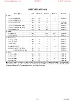
Page 3: ... 5 SP Mode 3 3 S N R P dB 36 41 SP Mode 3 4 Distortion R P 1 0 4 0 SP Mode 3 5 Freq resp R P at 200Hz dB 11 4 SP Mode 20dB ref 1kHz at 8kHz dB 14 4 SP Mode 4 Tuner 4 1 Video output Vp p 0 8 1 0 1 2 E E Mode 4 2 Video S N dB 39 42 E E Mode 4 3 Audio output dB 10 6 2 E E Mode 4 4 Audio S N dB 40 46 E E Mode Note Nominal specs represent the design specs All units should be able to approximate these s...

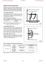
Page 4: ...uble insulated wires 3 High voltage leads D Use specified insulating materials for hazardous live parts Note especially 1 Insulation tape 2 PVC tubing 3 Spacers 4 Insulators for transistors E When replacing AC primary side components transformers power cord etc wrap ends of wires securely about the terminals before soldering F Observe that the wires do not contact heat produc ing parts heatsinks o...

Page 5: ...essible parts RF terminals an tenna terminals video and audio input and output ter minals microphone jacks earphone jacks etc is lower than or equal to the specified value in the table below Measuring Method Power ON Insert load Z between B earth ground power cord plug prongs and exposed accessible parts Use an AC voltmeter to measure across the terminals of load Z See Fig 2 and the following tabl...

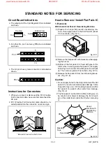
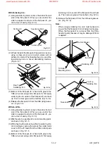
Page 6: ... ing the hot air 3 Bottom of the flat pack IC is fixed with glue to the CBA when removing entire flat pack IC first apply soldering iron to center of the flat pack IC and heat up Then remove glue will be melted Fig S 1 6 4 Release the flat pack IC from the CBA using tweez ers Fig S 1 6 Caution 1 Do not supply hot air to the chip parts around the flat pack IC for over 6 seconds because damage to th...

Page 7: ...easily Fig S 1 3 2 Affix the wire to a workbench or solid mounting point as shown in Fig S 1 5 3 While heating the pins using a fine tip soldering iron or hot air blower pull up the wire as the solder melts so as to lift the IC leads from the CBA contact pads as shown in Fig S 1 5 4 Bottom of the flat pack IC is fixed with glue to the CBA when removing entire flat pack IC first apply soldering iro...

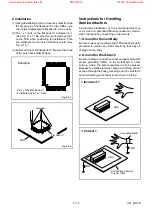
Page 8: ...lectro static charge during unpacking or repair work 1 Ground for Human Body Be sure to wear a grounding band 1MΩ that is properly grounded to remove any static electricity that may be charged on the body 2 Ground for Workbench Be sure to place a conductive sheet or copper plate with proper grounding 1MΩ on the workbench or other surface where the semiconductors are to be placed Because the static...

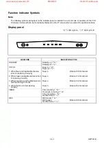
Page 9: ...an Mechanism is Not Functioning Correctly Tape in Blinks at 0 8Hz interval 2 When Tape Loading Mechanism is Not Functioning Correctly Tape in Blinks at 1 6Hz interval 3 When Cassette Loading Mechanism is Not Functioning Correctly Tape in Blinks at 3 2Hz interval 4 When the Drum is Not working properly Tape in Blinks at 6 4Hz interval TIMER Timer stand by H One touch recording H Timer recording H G...

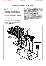
Page 10: ... are for 2 Head 4 Head and Hi Fi Use a connector indicated as shown Be careful not to let the unused connector contact other parts Note 2 Some noise will be present in the playback picture when the extension cable is used Note 3 Before installing the Deck Assembly be sure to align two triangle marks of SW1001 on U21 Deck Ex tension Cable B Then install the Deck Assembly while aligning the hole of ...

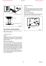
Page 11: ...e connected before plugging in the unit the function of the sensors will stay valid See Fig 3 Note Because the Tape End Sensors are inactive do not run a tape all the way to the start or the end of the tape to avoid tape damage About REC Safety Switch Caution The REC Safety Switch is directly mounted on the Main CBA When the Deck Mechanism Assembly is removed from the Main CBA for servicing this s...

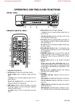
Page 12: ...off Press to activate a timer recording If you have a PHILIPS TV press to turn your PHILIPS TV power on and off 8 SPEED button Press to set desired recording speed System Change Function VR109 55 only Press to change the VCR system for matching recorded system PAL or MESECAM during playback only on the VCR 9 Remote sensor window Receives the infrared signals from the remote control 10 Indicator ST...

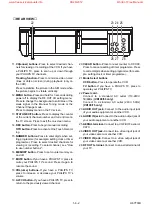
Page 13: ...MUTE button If you have a PHILIPS TV press to mute your PHILIPS TV s sound Press it again to resume the sound 18 VOL ume buttons If you have a PHILIPS TV press to increase or decrease your PHILIPS TV s volume 19 ALT CH button If you have a PHILIPS TV press to return to the previously viewed channel 20 CLEAR button Press to reset counter to 0 00 00 Press to cancel a setting of timer programme Press...

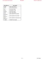
Page 14: ...for Full Erase Head FG GND Ground for C FG F1 F2 Filament Voltage 1 2 GND Ground DC 0V Signal Name Description G1 G4 Grid Control Output 1 4 H SYNC Horizontal Synchronized Pulse KEY 1 Key Scan Input Signal 1 KEY 2 Key Scan Input Signal 2 I2C BUS DATA Serial Data for Tuner I2C BUS CLK Serial Clock for Tuner LD M Loading Motor Forward Drive LD M Loading Motor Reverse Drive LD SW Deck Mode Position D...

Page 15: ...e Video In Front V MUTE Video Mute Signal V OUT Video Output Signal YCA Hi Fi DATA Video Audio Hi Fi Serial Data YCA Hi Fi CLK Video Audio Hi Fi Serial Clock YCA Hi Fi CS L Video Audio Hi Fi Chip Select Low 3 58MHZ 3 58MHZ Clock Signal 1 7 2 H67T0SNA www freeservicemanuals info 06 28 2012 World of Free Manuals ...

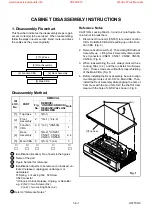
Page 16: ...nects five Connectors CN251 CN501 CN502 CN503 CN504 Fig 4 3 When reassembling the unit always reinsert three Locking Tabs L 4 and then reinstall two Screws S 3 These screws are critical for proper shielding of the Main CBA Fig 5 4 Before installing the Deck Assembly be sure to align two triangle marks of LD SW on Main CBA Then install the Deck Assembly while aligning the hole of Cam Gear with the ...

Page 17: ...eck Assembly CN502 CN503 Fig 4 S 3 L 4 L 4 5 Main C B A Fig 5 L 2 L 1 2 Front Assembly 3 Function C B A L 2 Fig 2 5 Main C B A SW507 LD SW LD SW Pin Hole Hole Shaft Cam Gear 5 Main C B A 4 Deck Assembly Triangle Marks Fig 6 1 8 2 H67T0DC www freeservicemanuals info 06 28 2012 World of Free Manuals ...

Page 18: ... DC 20MHz 2 Alignment Tape 4822 395 10283 1 Head Switching Position Adjustment Purpose To determine the Head Switching point dur ing playback Symptom of Misadjustment May cause Head Switching noise or vertical jitter in the picture Test Point Adj Point Mode Input TP751 V OUT TP302 RF SW GND VR501 SW P PLAY SP Tape Measurement Equipment Spec 4822 395 10283 Oscilloscope 6 5H 1H 412 7 60µs Connection...

Page 19: ...P TP502 SENS INH Test Point TP301 TP302 TP303 J267 TP502 Used in Page No Mechanical Alignment Procedures Mechanical Alignment Procedures Mechanical Alignment Procedures Preparation for Servicing Preparation for Servicing 2 3 3 2 3 4 2 3 3 2 3 4 2 3 3 1 5 1 1 5 2 TEST POINTS NOT USED IN ELECTRICAL ADJUSTMENTS Tuner Unit Main CBA Antenna In Video In Audio In Audio Out Video Out Antenna Out TUNER BLO...

Page 20: ...V TP506 TP507 TP505 T REEL DEC L DEC L 83 BUS SCL BUS SDA BUS SCL 79 OSD CS L 80 OSD DATA 81 OSD CLK OSD CS L OSD DATA OSD CLK BUS SDA TO VIDEO BLOCK TO AUDIO BLOCK BUS SDA BUS SCL TO JACK BLOCK 2 2 KEY 2 4 4 KEY 1 KEY SWITCH KEY SWITCH KEY SWITCH TP501 GND TP502 S INH CN505 CN651 FUNCTION CBA 1 10 1 1 10 2 H67T0BLS SCL SDA TU701 SCL SDA 6 5 16 17 18 19 4 5 10 9 8 14 6 15 13 12 11 7 2 8 LD SW 26 D...

Page 21: ...P BPF BPF D E NL EMPHA C COMB COMB AMP CCD LPF BPF KIL Q302 Q303 PEAKING AMP REC FM EQ PB FM EQ FM MOD DETAIL ENH W D CLIP CLAMP MAIN CBA 74 WF2 TP301 C PB WF5 10 BUFFER Q305 TO SERVO SYSTEM CONTROL BLOCK D V SYNC OSD CS L OSD CLK OSD DATA C SYNC ROTA ROTA TU701 VIDEO TP751 V OUT 6 TU VIDEO 24 26 IC301 IC851 Y C PROCESS OSD 28 C SYNC 15 13 18 11 10 9 OSD CHARACTER MIC WF1 38 36 32 31 EE AGC LINE T...

Page 22: ...O SIGNAL REC AUDIO SIGNAL Mode SP REC 10 D REC H A MUTE H BUS SCL BUS SDA TO SERVO SYSTEM CONTROL BLOCK FULL ERASE HEAD 23 24 SERIAL DECODER 98 DECK ASSEMBLY SMD NOTE FOR WIRE CONNECTORS 1 PREFIX SYMBOL CN MEANS CONNECTOR CAN DISCONNECT AND RECONNECT 2 PREFIX SYMBOL CL MEANS WIRE SOLDER HOLES OF THE PCB WIRE IS SOLDERED DIRECTLY TEST POINT INFORMATION INDICATES A TEST POINT WITH A JUMPER WIRE ACRO...

Page 23: ...t are not defective before you connect the AC plug to the AC power supply Otherwise it may cause some components in the power supply circuit to fail H67T0BLP 1 10 7 1 10 8 COLD MAIN CBA HOT CIRCUIT BE CAREFUL HOT IC001 ERROR VOLTAGE DET Q002 Q003 Q001 F001 T1 6AL 250V L002 LINE FILTER BRIDGE RECTIFIER D001 D004 1 2 3 4 Q004 SHUNT REGULATOR REG AC001 T001 AL 44V 12 AL 12V P ON L P ON 12V AL 5V TIME...

Page 24: ...liability of re paired units use only original replacement parts which are listed with their part numbers in the parts list section of the service manual 3 Prefix symbol CN means connector can discon nect and reconnect Prefix symbol CL means wire solder holes of the PCB wire is soldered directly 4 How to read converged lines 1 D3 Distinction Area Line Number 1 to 3 digits Examples 1 1 D3 means tha...

Page 25: ...C536 E 3 L502 B 2 R543 C 4 C538 E 1 L503 F 3 R549 B 2 SW501 F 5 C542 E 3 L504 B 1 R554 C 1 SW502 F 5 C543 F 3 R558 D 1 SW503 F 5 C545 F 3 Q503 D 4 R561 D 1 SW505 F 5 C546 F 3 Q504 D 4 R562 D 1 SW506 D 1 C548 D 2 Q505 F 2 R563 E 2 SW507 C 4 C549 F 2 Q506 E 3 R566 D 1 C554 F 2 Q508 E 4 R568 E 2 VR501 F 2 C555 E 2 R569 E 2 C556 D 1 R501 D 4 R570 F 2 X501 B 3 C611 E 3 R502 D 4 R571 F 2 X502 E 3 C614 E...

Page 26: ...No KEY 1 31 PIN KEY 2 27 PIN Voltage O O D T u POWER CH UP O D T O D X u SPEED STOP EJECT O D X P D Q Q u FF P D Q Q P D T T u CH DOWN REW P D T T P D X Q u S INH PLAY P D X Q Q D R T u PAUSE Q D R T Q D X O u MENU REC Q D X O R D U O u STATUS EXIT R D U O S D R O u S D R O u T D O u KEY OFF KEY OFF Comparison Chart of Models and Marks MODEL MARK VR109 55 A VR109 75 B www freeservicemanuals info 0...

Page 27: ...J 4 L853 J 2 C711 J 4 C721 J 3 R703 I 3 C722 J 4 R706 I 3 C723 J 4 R707 I 3 C724 J 4 R714 J 3 C851 J 3 R715 J 4 C854 I 2 R751 I 1 C855 I 2 R752 I 1 C856 I 2 R753 I 1 C857 I 2 R755 J 1 C858 I 2 R851 I 2 C859 I 2 R852 I 2 C860 J 2 R853 I 2 C862 J 2 R854 J 2 C863 J 2 JK751 J 1 D701 I 3 JK752 J 1 TU701 I 4 IC851 I 3 TP751 J 1 L701 I 4 TP752 I 1 DIODES CAPACITORS COILS MISCELLANEOUS TEST POINTS COILS R...

Page 28: ...317 O 1 C339 P 3 R318 P 1 C340 P 3 R319 P 1 C341 O 4 R320 P 1 C342 P 4 R321 P 4 C344 O 3 R322 P 4 C345 O 3 R325 P 2 C346 O 3 R326 P 2 C348 O 3 R327 P 2 C349 O 3 R328 Q 3 C350 O 3 R329 O 1 C351 O 3 R330 O 1 C352 O 3 R331 P 2 C353 O 4 R334 O 4 C354 O 4 R335 O 3 C355 P 2 R336 O 3 C357 P 2 R341 P 2 C381 P 3 R401 M 2 C401 N 2 R402 M 2 C403 N 2 R403 M 2 C404 N 2 R404 M 2 C405 N 2 R405 N 2 C406 N 2 R406 ...

Page 29: ... 1 R658 B 1 SW659 B 1 RESISTORS CONNECTORS SWITCHES RESISTORS MAIN 4 4 Schematic Diagram Parts Location Guide Ref No Position Ref No Position C001 R 2 L006 U 2 C003 R 2 L007 T 2 C004 S 2 L008 T 2 C005 S 2 L009 T 2 C006 S 2 C007 S 2 Q001 S 2 C008 R 1 Q002 S 2 C010 R 1 Q003 R 1 C011 R 1 Q004 T 1 C012 T 2 Q054 V 1 C015 V 2 Q056 V 1 C016 T 2 Q057 U 2 C017 T 2 C018 T 2 R001 R 2 C020 T 2 R002 S 2 C021 T...

Page 30: ...T A VARIABLE ISOLATION TRANSFORMER IS REQUIRED NOTE THE VOLTAGE FOR PARTS IN HOT CIRCUIT IS MEASURED USING HOT GND AS A COMMON TERMINAL CAUTION FOR CONTINUED PROTECTION AGAINST FIRE HAZARD REPLACE ONLY WITH THE SAME TYPE FUSE CAUTION Fixed voltage or Auto voltage selectable power supply circuit is used in this unit If Main Fuse F001 is blown check to see that all components in the power supply cir...

Page 31: ...R PARTS IN HOT CIRCUIT IS MEASURED USING HOT GND AS A COMMON TERMINAL CAUTION FOR CONTINUED PROTECTION AGAINST FIRE HAZARD REPLACE ONLY WITH THE SAME TYPE FUSE CAUTION Fixed voltage or Auto voltage selectable power supply circuit is used in this unit If Main Fuse F001 is blown check to see that all components in the power supply circuit are not defective before you connect the AC plug to the AC po...

Page 32: ...B 3 L002 F 4 R009 F 3 R403 D 4 R562 C 1 C305 D 4 C412 D 4 C857 B 3 L003 F 1 R010 G 3 R404 D 4 R563 B 1 X302 C 3 C306 D 3 C413 D 4 C858 B 3 L004 F 4 R011 G 3 R405 E 4 R566 B 1 X501 C 1 C307 D 3 C414 D 4 C859 B 3 L006 F 3 R012 G 3 R406 E 4 R568 F 1 X502 D 2 C308 D 3 C415 D 4 C860 A 3 L007 G 2 R013 F 3 R408 E 4 R569 F 1 C310 D 3 C416 B 4 C862 A 3 L008 G 2 R014 F 3 R409 E 4 R570 F 1 AC001 F 4 C311 D 3...

Page 33: ...uide Ref No Position Ref No Position CN651 A 1 R659 B 1 R651 A 1 SW651 A 2 R652 A 2 SW652 B 2 R653 A 1 SW653 A 2 R654 A 2 SW654 B 2 R655 A 2 SW655 A 2 R656 A 1 SW656 B 1 R657 A 1 SW658 A 1 R658 A 1 SW659 A 1 CONNECTORS SWITCHES RESISTORS RESISTORS www freeservicemanuals info 06 28 2012 World of Free Manuals ...

Page 34: ... of Main CBA WF1 UPPER WF2 LOWER V OUT 0 1V x 10 RF SW 0 5V x 10 50usec TP751 of Main CBA TP302 of Main CBA WF5 C PB 10mV x 10 RF SW 0 5V x 10 5msec UPPER LOWER WF2 TP302 of Main CBA TP301 of Main CBA www freeservicemanuals info 06 28 2012 World of Free Manuals ...

Page 35: ...2 PG 6 D V 2 D U 1 AL 5V 1 C F R 2 C FG 3 AL 12V 4 NU 5 C DRIVE 6 FG GND 7 CM GND 8 FE H 1 FE H GND 2 CN501 CN504 V L 1 V COM 2 NU 3 V R 4 CN251 CN503 CAPSTAN MOTOR AL 5V C F R C FG AL 12V NU C DRIVE FG GND CM GND FULL ERASE HEAD FE HEAD VIDEO L HEAD VIDEO R HEAD DECK ASSEMBLY M DRUM MOTOR PG SENSOR NU 1 1 KEY 2 2 2 GND 3 3 KEY 1 4 4 CN651 CN505 NOTE FOR WIRE CONNECTORS 1 PREFIX SYMBOL CN MEANS CO...

Page 36: ...4V 2 96V SS 4 70V 5 00V 5 00V GC 3 35V 4 05V 3 69V RS EJ RS Loading FWD LM FWD H LM REV L RS EJ Loading REV LM FWD L LM REV H Stop A Loading Stop B Unloading Note Symbol Loading Status EJ Eject CL Eject REW Reel SB REW Reel Stop B TL Stop B Brake Cancel LC Loading Switching Brake Cancel FB Brake Cancel SF Stop A AU Stop A Play REC AL Play REC Still Slow SS Still Slow Capstan Reversal GC Capstan Re...

Page 37: ... 0 2S PIN NO CL SB TL 0 2S LC FB GC SF SF RS GC SS AL AL AU AU SF AU AL AL SS AU AU AU 26 LD SW 48 LM FWD 49 LM REV 5 C DRIVE 10 C F R DRUM ROTATION 97 P ON POWER OFF STOP PLAY RS FS STILL STOP PLAY PLAY 1 A MUTE H YCA DATA 19 D REC H 98 D PB L DISPLAY PAUSE ON PAUSE OFF PAUSE OFF PAUSE ON 0 2S 0 2S 0 8S 0 1S 0 2S 0 2S 0 4S 0 5S 0 2S 0 2S 0 2S 0 2S 5 0S 5 0S 0 2S 0 2S 0 2S 0 2S 0 1S 0 3S 1 0S 0 8S...

Page 38: ...6 LD SW 48 LM FWD 49 LM REV 5 C DRIVE 10 C F R DRUM ROTATION 97 P ON FF STOP STOP REC REC REC PAUSE REW STOP 1 A MUTE H YCA DATA 19 D REC H 98 D PB L DISPLAY REC or PAUSE REC PAUSE REC PAUSE REC STOP EJECT STOP EJECT STOP EJECT ST S END S ON REW STOP REC EE PB SF FB 0 2S 0 2S 0 2S 0 2S 0 2S 0 2S 1 3S 0 2S 0 2S 0 2S 0 2S 0 2S 20mS 0 2S 0 2S 0 2S 1S 1 2S 0 2S 0 2S 0 2S 0 2S 12mS 12mS 12mS LC FB AU A...

Page 39: ...d Pulse H Z 18 N U Not Used 19 OUT D REC H Delayed Record Signal Recording H H 20 N U Not Used Pin No Mark IN OUT Signal Name Function Active Level 21 IN REC SW Record Safety Switching Signal H 22 IN AFC Automatic Frequency Control Signal A D 23 IN V ENV Video Envelope Signal A D 24 IN END S Tape END Position Detect Signal A D 25 IN ST S Tape Start Position Detect Signal A D 26 IN LD SW Deck Mode ...

Page 40: ...ed 53 N U Not Used 54 N U Not Used Pin No Mark IN OUT Signal Name Function Active Level 55 N U Not Used 56 N U Not Used 57 N U Not Used 58 N U Not Used 59 N U Not Used 60 N U Not Used 61 N U Not Used 62 OUT REC LED REC Mode LED Indicator H L 63 OUT TIMER LED TIMER Mode LED Indicator H L 64 OUT CAS LED CASSETTE IN OUT LED Indicator H L 65 N U Not Used 66 N U Not Used 67 N U Not Used 68 N U Not Used...

Page 41: ...H L 92 OUT BUS SCL IICBUS Control Clock H L 93 N U Not Used 94 OUT SW1 Tuner System Control H L 95 N U Not Used 96 OUT SW2 Tuner System Control H L 97 OUT P ON L Power On Signal at Low L 98 N U Not Used 99 N U Not Used 100 N U Not Used Notes Abbreviation for Active Level PWM Pulse Wide Modulation A D Analog Digital Converter 1 15 3 H67T0PIN www freeservicemanuals info 06 28 2012 World of Free Manu...

Page 42: ...2058 Q DTA124ESA KRA103M KRC103M DTC124ESA E C B BN1F4M T BA1F4M T KTA1266 Y GR KTC3193 Y KTA1267 Y GR 2SA1175 J H F 2SA608 E F KTC3199 Y GR BL 2SC2785 J H F K 2SA933AS Q R S 2SC1740S Q R 2SC1815 BL TPE2 2SC1815 Y TPE2 2SC1815 GR TPE2 2SC3331 T U 2SC2120 Y TPE2 2SA1015 GR TPE2 E C B E C B 2SC536NF NG NPA AT E C ST 304L A B C D E RPI 302 K C S D G FS2KM 18A FS1KM 18A LB11880 1 15 30 16 LC74793 9173...

Page 43: ...scription ServiceCode D003 1N5061 4822 130 31933 D004 1N5061 4822 130 31933 D005 BYV96E 5322 130 34979 D006 1SS133 4822 130 32778 D007 1SS133 4822 130 32778 D008 1SS133 4822 130 32778 D009 1SS133 4822 130 32778 D010 A MTZJ33D 4822 130 81729 D011 BYV95C 4822 130 41487 D013 BYV95C 4822 130 41487 D014 ERB81 004 4822 130 80601 D015 MTZJ9 1C 4822 130 80319 D019 ZENER DIODE MTZJT 775 6B 9965 000 05249 D...

Page 44: ... 000 05240 2L041 A SCREW 3X8 4822 502 14667 AC001 A AC CORD 9707020 4822 321 11411 AC001 B AC CORD LA 1865 9965 000 06565 F001 21801 6 1 6A 4822 070 31602 FH001 FUSE HOLDER MSF 015 4822 256 10461 FH002 FUSE HOLDER MSF 015 4822 256 10461 JK751 4822 264 10286 JK751 4822 264 10286 PS501 PHOTO INTERRUPTER RPI 302 9965 000 05254 RS501 PIC 26042LU 4822 130 11648 SA001 JVR 10N471K 4822 252 11373 T001 A P...

Page 45: ...H67T0FEX 1 18 1 Front Panel EXPLODED VIEWS A1X A17 www freeservicemanuals info 06 28 2012 World of Free Manuals ...

Page 46: ...AC001 Cabinet Cabinet See Electrical Parts List for parts with this mark Some Ref Numbers are not in sequence 2L031 2L031 2B8 RS501 2B34 2B3 2B3 FUNCTION CBA 2B11 2L041 2L031 1B1 2L021 2L021 2L021 2L021 2L021 www freeservicemanuals info 06 28 2012 World of Free Manuals ...

Page 47: ...S2 S3 Unit S2 1 18 3 Packing H67T0PEX X20 X2 X4 S1 Some Ref Numbers are not in sequence X1 X3 A14 A14 X5 X30 A14 S6 S5 www freeservicemanuals info 06 28 2012 World of Free Manuals ...

Page 48: ...AY 9965 000 05231 B359 CLEANER LEVER MK9 9965 000 05233 B360 CLEANER ROLLER MK9 9965 000 06561 B529 CLEANER ASSY MK9 9965 000 05235 2B5 PLATE SHIELD U21 H5700UD 9965 000 05630 2L011 SCREW 3X10 4822 502 14666 2L021 4822 502 30752 2L031 M 3 X 8 4822 502 14012 ACCESSORIES X1 REMOTE 364 CRC004 9965 000 06519 X3 CONNECT CABLE PAL 4822 320 50377 X20 A OWNER S MANUAL VR109 55 9965 000 06520 X20 B OWNER S...

Page 49: ...iews Deck Parts List TABLE OF CONTENTS STANDARD MAINTENANCE 2 1 1 SERVICE FIXTURE AND TOOLS 2 2 1 MECHANICAL ALIGNMENT PROCEDURES 2 3 1 DISASSEMBLY ASSEMBLY PROCEDURES OF DECK MECHANISM 2 4 1 FRONT LOADING ASSEMBLY 2 4 8 ALIGNMENT PROCEDURES OF MECHANISM 2 4 10 DECK EXPLODED VIEWS 2 5 1 DECK PARTS LIST 2 6 1 H67T0CV www freeservicemanuals info 06 28 2012 World of Free Manuals ...

Page 50: ...Capstan Belt B73 FE Head CBA B133 Idler Assembly B410 Pinch Arm A Assembly B414 Main Brake S Assembly B416 Main Brake T Sub Assembly B525 Loading Belt Notes 1 Clean all parts for the tape transport Upper Drum with Video Head Pinch Roller Audio Control Head Full Erase Head using 90 Isopropyl Alcohol 2 After cleaning the parts do all DECK ADJUSTMENTS 3 For the reference numbers listed above refer to...

Page 51: ...id cleaning it verti cally 2 Wait for the cleaned part to dry thoroughly before operating the unit 3 Do not reuse a stained head cleaning stick or a stained chamois cloth Cleaning of Audio Control Head Clean the head with a cotton swab Procedure 1 Remove the top cabinet 2 Dip the cotton swab in 90 isopropyl alcohol and clean the audio control head Be careful not to damage the upper drum and other ...

Page 52: ... Roller J 3 Mirror 4822 380 10108 Tape Transportation Check J 4 Azimuth Adj Screwdriver Available Locally A C Head Height J 5 X Value Adj Screwdriver Available Locally X Value J 6 U21 Deck Extension Cable 4822 320 12718 All Mechanical and Electrical Adjustments Note Before starting any adjustment take the Deck Assembly out of the cabinet and use J 6 to connect the Deck Assembly with the Main CBA J...

Page 53: ...guide assemblies are in the Eject Position go to step 6 4 First turn the LDG Belt B in the appropriate direc tion shown in Fig M1 until the First Gear starts turning 5 Stop turning the LDG Belt B immediately after the First Gear starts turning 6 Turn the First Gear in the appropriate direction until Moving guide assemblies come to the Eject Posi tion Stop turning when the assemblies begin clicking...

Page 54: ... and that there is no slack on the supply and take up side Guide Rollers Use a blank tape Adjust the height of the Guide Rollers Supply side and take up side Use a blank tape pg 2 3 3 Loading Use a blank tape Adjust the envelope pg 2 3 4 Check the envelope Adjust the Audio Section Azimuth Alignment pg 2 3 4 Check the audio output Check the following 1 X Value pg 2 3 3 2 Envelope pg 2 3 4 Adjust th...

Page 55: ... of the AC Head Fig M6 1 B X Value Alignment Purpose To align the Horizontal Position of the Audio Con trol Erase Head Symptom of Misalignment If the Horizontal Position of the Audio Control Erase Head is not properly aligned maximum envelope can not be obtained at the Neutral position of the Tracking Control Circuit 1 Connect the oscilloscope to TP301 C PB and TP303 CTL on the Main CBA Use TP302 ...

Page 56: ... M3 so that the waveform looks like the one shown in Fig M9 4 If the envelope is as shown in Fig M8 adjust the height of Guide Roller 3 Refer to Fig M3 so that the waveform looks like the one shown in Fig M9 5 When Guide Rollers 2 and 3 Refer to Fig M3 are aligned properly there is no envelope drop either at the beginning or end of track as shown in Fig M9 Note Upon completion of the adjustment of...

Page 57: ...ding Motor Assembly T DM1 DM5 S 6 LDG Belt B ACH Connector AN 9P and B 9P 6 5 Loading Motor Holder T DM1 DM5 2 S 7 L 1 7 5 AC Head Assembly T DM1 DM6 2 S 8 8 8 Tape Guide Assembly T DM1 DM6 P 1 P 2 C 1 9 9 Door Opener B T DM1 DM6 S 9 L 2 10 9 Pinch Arm A Assembly T DM1 DM6 P 3 11 10 Pinch Arm B Assembly T DM1 DM6 E ring 12 8 Capstan Motor B DM2 DM7 3 S 10 Capstan Belt 13 13 Cam Gear B B DM2 DM8 C ...

Page 58: ...ART REMOVAL INSTALLATION Fig No REMOVE UNHOOK UNLOCK RELEASE UNPLUG DESOLDER ADJUSTMENT CONDITION 31 30 Tension Lever Assembly T DM1 DM11 P 7 C 6 32 31 Tension Lever Sub Assembly T DM1 DM11 33 31 Reel S Assembly T DM1 DM11 C 7 Poly Slider Washer 34 29 Reel T Assembly T DM1 DM11 C 8 Poly Slider Washer 35 33 Reel Shaft T DM1 DM11 2 S 19 36 18 First Gear B DM2 DM12 C 9 37 36 Second Gear B DM2 DM12 C ...

Page 59: ...9 40 36 14 15 18 21 22 23 13 Bottom View Fig DM2 4 45 44 46 7 28 6 10 5 11 27 38 29 17 34 35 39 33 35 24 30 32 43 25 26 31 8 9 Top View Fig DM1 2 4 3 H67T0DA www freeservicemanuals info 06 28 2012 World of Free Manuals ...

Page 60: ...r B 3 Remove Screw 2 S 2 4 Lift it up slightly and then slide Front Loading Assembly S 3 S 2 S 1 S 3 S 2 S 4 Bottom View Locking Tab Rec Arm turn Fig DM3 CN287 ACH Connector AN 9P ACH Connector B 9P 5 6 S 6 L 1 S 7 LDG Belt B FFC Cable Fig DM5 4 S 5 S 5 45 46 Connector Connector Fig DM4 2 4 4 H67T0DA www freeservicemanuals info 06 28 2012 World of Free Manuals ...

Page 61: ...embling 13 be sure to slide 19 until the left edge of 19 touches 13 as shown in Fig DM7 Fig DM8 11 E ring P 3 C 1 11 21 Pin of 11 7 8 9 L 2 P 1 Adj Screw S 9 S 8 10 S 8 B A View for A When reassembling 11 confirm that pin of 11 is in the groove of 21 as shown P 2 View for B P 2 Fig DM6 2 4 5 H67T0DA www freeservicemanuals info 06 28 2012 World of Free Manuals ...

Page 62: ...6 P 7 S 20 34 35 Pole 35 Poly Slider Washer Poly Slider Washer Pole Base of the Chassis 2 0 2 mm 0 08 0 008 inch Fig DM11 36 37 C 10 C 9 W 2 Fig DM12 18 17 Pin of 18 Pin of 40 Pin of 38 Pin of 29 Pin of 30 L 3 19 20 21 23 22 S 14 C 5 S 13 S 12 L 3 Position of Mode Lever when installed Hole When reassembling 21 confirm that the hole on 21 is in the correct position as shown W 1 Fig DM9 2 4 6 H67T0D...

Page 63: ...0 Refer to the Alignment Section Page 2 4 10 41 C 11 42 Fig DM14 43 44 Guide Roller Height 26 325 0 1 mm Fig DM15 38 39 Fig DM13 2 4 7 H67T0DA www freeservicemanuals info 06 28 2012 World of Free Manuals ...

Page 64: ...7 DM18 Eject Position 14 13 Cassette Drive Lever R DM17 Cassette Drive Spring Eject Position 15 14 Front Door Opener R DM17 DM18 L 3 1 Follow steps in sequence When reassembling follow the steps in reverse order These numbers are also used as Identification location No of parts in the figures 2 Indicates the part to start disassembling with in order to disassemble the part in column 1 3 Name of th...

Page 65: ...all 2 and 3 in Eject position When disassembling 2 and 3 can be removed either in Eject position or Cassette in position This figure shows where 2 3 and other parts are in Eject position Fig DM16 12 13 15 L 3 Cassette Drive Spring When reassembling 12 and 13 refer to the Alignment Section Pg 2 4 11 This figure shows where 12 13 15 and other parts are in Eject position Fig DM18 2 4 9 MK9FL www free...

Page 66: ...Position Alignment 1 Loading Arm S and T Assembly Install Loading Arm S and T Assembly so that their triangle marks point to each other as shown in Fig AL2 Alignment 2 Mode Gear Keeping the two triangles pointing at each other in stall the Loading Arm T Assembly so that the last tooth of the gear meets the most inside teeth of the Mode Gear See Fig AL2 Alignment a Tape Guide Arm Assembly Measureme...

Page 67: ...lignment 4 Cam Gear A Cassette Drive Sub Gear Install the Front Loading Assembly so that the trian gle mark of Cassette Drive Sub Gear is aligned with the indent of the Cam Gear A as shown in Fig AL4 Triangle Mark Indent Cassette Drive Sub Gear Alignment 4 Triangle Marks Cassette Drive Gear Alignment 3 Fig AL4 2 4 11 U21APM2H www freeservicemanuals info 06 28 2012 World of Free Manuals ...

Page 68: ...D No B37 Capstan Motor L1051 Black MMDZB25SJ001 GPMB9060 MMDZB12SJ007 GPMS9060 Silver B518 B553 Table 1 B37 and L1051 Combination Note Two different but interchangeable types of Capstan Motor B37 may be installed in these models Please confirm B37 CAPSTAN MOTOR Type by color B37 CAPSTAN MOTOR type varies in combination with L1051 Please see Table 1 for details and combination Refer to DECK PARTS L...

Page 69: ...tom Side Grease point Bottom Side Grease point B513 B496 B505 B504 B38 B534 B490 B516 B52 B495 B500 L1462 B517 L1468 B498 B475 B508 B485 L1469 L1463 L1465 B522 B506 L1475 B148 B361 B359 B529 B360 B540 Some Ref Numbers are not in sequence B359 B360 and B529 See the Mechanical Parts List A View for A Grease Point B488 L1464 B555 B126 L1466 B121 B427 B426 B8 B501 L1476 1 2 3 4 D E F Deck Mechanism Vi...

Page 70: ...lue grease B482 B354 B304 B319 L1341 L1342 L1461 B425 B483 B345 B476 B344 B352 B313 B481 B493 B511 B533 B532 B531 B303 B421 B420 B350 B472 L1467 L1081 B514 Some Ref Numbers are not in sequence 1 2 3 4 D E F Deck Mechanism View 3 2 5 3 H67T0DEX www freeservicemanuals info 06 28 2012 World of Free Manuals ...

Page 71: ...7 B423 CYLINDER SHIELD MK9 9965 000 05307 B425 LOCK LEVER SPRING MK9 9965 000 05308 Ref No Description ServiceCode B426 KICK PULLEY MK9 9965 000 05309 B427 KICK SPRING MK9 9965 000 05310 B472 SLIDER R ASSY MK9 9965 000 05311 B473 SLIDER L ASSY MK9 9965 000 05312 B475 BT ARM ASSY MK9 9965 000 05313 B476 REC ARM ASSY MK9 9965 000 05374 B480 PINCH ARM B ASSY MK9 9965 000 05314 B481 C DRIVE SUB GEAR M...

Page 72: ... 4822 502 14668 L1461 4822 502 30471 L1462 SCREW M2 6X12 PAN HEAD 9965 000 05361 L1463 SCREW M2 6X4 BIND HEAD 9965 000 05362 L1464 SCREW GUIDE ROLLER PPS 9965 000 05363 L1465 SCREW M2 6X4 BIND HEAD 9965 000 05362 L1466 M 3 X 6 4822 502 14009 L1467 4822 502 30752 L1468 4822 502 30471 L1469 SCREW M2 6X6 BIND HEAD 9965 000 05364 L1471 SCREW M2 6X6 BIND HEAD 9965 000 05364 L1475 4822 502 30471 L1476 S...

Reviews: