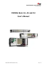
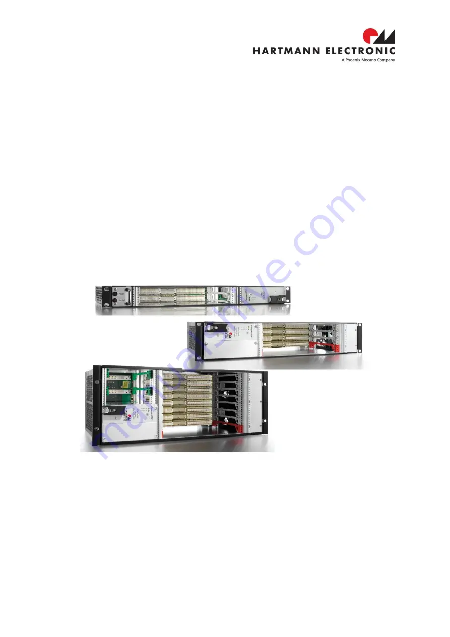
Phoenix Mecano HARTMANN ELECTRONIC VME64x Basic 1U, User Manual
The Phoenix Mecano HARTMANN ELECTRONIC VME64x Basic 1U comes with a comprehensive User Manual for easy installation and operation. Get the manual for free download at 88.208.23.73:8080 with detailed instructions and troubleshooting tips to maximize the performance of this innovative VME64x Basic 1U unit.
Share
Download
Reviews:
No comments
Related manuals for HARTMANN ELECTRONIC VME64x Basic 1U

NI PXI-1045
Brand: National Instruments Pages: 65

MAXNET II Platinum Series
Brand: ATX Pages: 36

NI 9144
Brand: National Instruments Pages: 12

PowerConnect B-DCX-4S Backbone
Brand: Dell Pages: 134

Force10 E300
Brand: Dell Pages: 1262

MASTER series
Brand: Turin Networks Pages: 36
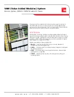
VAM (Value Added Modules) System
Brand: ADC Pages: 4

9C106
Brand: Cabletron Systems Pages: 40

Q-1300
Brand: Thinklogical Pages: 20

VelocityKVM VTM-004200
Brand: Thinklogical Pages: 27

Socle Box
Brand: Riello Pages: 8

MT45 2019
Brand: freightliner Pages: 89


