background image


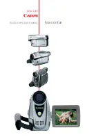
FASTCAM-APX RS 

Hardware Manual 


Rev.1.05 


PHOTRON LIMITED 

MAR.2006 


Summary of Contents for FASTCAM-APX RS

Page 1: ...FASTCAM APX RS Hardware Manual Rev 1 05 PHOTRON LIMITED MAR 2006...

Page 2: ......

Page 3: ...era Components 18 2 2 3 Changeable Lens Mount 19 2 2 4 Installing Heat Sink optional 20 2 2 5 Remote Control Keypad 21 2 2 6 GENERAL IN Cable 22 2 2 7 GENERAL OUT Cable 23 2 2 8 MCDL RS422 Cable Optio...

Page 4: ...1 Initialization Calibration 40 3 1 1 Start Calibration 40 3 1 2 Saving Calibrated Settings 41 3 1 3 Loading Calibrated Settings 41 3 2 Selecting Frame Rate 42 3 3 Selecting Resolution 43 3 4 Selectin...

Page 5: ...epare for Memory Partitioning Set Number of Sections 81 3 8 2 Recording into Divided Sections 83 3 8 3 Playback of Recorded Sections 83 3 8 4 PARTITION MODE 84 3 9 LUT Look Up Table Operation 85 3 9 1...

Page 6: ...117 4 3 Slow Playback Jog 118 4 4 Zooming Zoom Fit Scroll 119 4 4 1 Fitting Image Frame to Video Screen 120 4 4 2 Zooming Playback Image Frame 121 4 4 3 Scrolling Playback Image Frame 122 4 5 Block P...

Page 7: ...n 152 6 1 3 Standard Equipment and Optional Items 153 6 1 4 Frame Rates and Resolutions 154 6 1 5 Number of Recorded Images vs Resolution 158 6 1 6 RS422 Serial Control Commands 159 6 1 7 STATUS OUT 1...

Page 8: ...FASTCAM APX RS Hardware Manual 6 Memo...

Page 9: ...FASTCAM APX RS Hardware Manual 7 Chapter 1 Introduction 1 1 Preface 1 2 Warranty 1 3 How to Use This Manual 1 4 Precautions...

Page 10: ...or analyzing captured events immediately which has been very difficult with conventional systems You will find this new recording technology most useful to capture the image of high speed moving subje...

Page 11: ...to PHOTRON at any of the addresses shown below repairs will be made at no charge 2 Parts replacement Replacement parts installed under warranty will be provided at no charge THIS WARRANTY DOES NOT AP...

Page 12: ...ng from the sale use or improper functioning of this equipment even if loss or damage is caused by the negligence or other fault of PHOTRON LIMITED PHOTRON USA INC or PHOTRON EUROPE LIMITED Return the...

Page 13: ...ipment and related peripheral devices Warning presents very important information regarding safety of the operators If it is neglected and the equipment is used in the wrong manner a serious hazardous...

Page 14: ...Chapter 5 Connection to a PC Shows how to connect and operate the APX RS to a PC Operation of the APX RS from PC is discussed in the PFV Software Manual Chapter 6 Specifications Provides detailed spe...

Page 15: ...A loss of the protective grounding for any reason could result in electrical shock Use the proper power cord and insure that it is in good condition FEDERAL COMMUNICATIONS COMMISSION STATEMENTS WARNIN...

Page 16: ...FASTCAM APX RS Hardware Manual 14 Memo...

Page 17: ...TCAM APX RS Hardware Manual 15 Chapter 2 Setting Up 2 1 To Start 2 2 Names of Components 2 3 System Connection 2 4 Basics of Remote Control Keypad Operation 2 5 System Setup 2 6 Back to Factory Settin...

Page 18: ...17 Cable clamps 4 ea 18 Optical PCI Interface Board 1 ea 19 Digital Interface Cable LAN Cable 1 ea 20 IP Address sticker 1 ea 21 Setup Manual 1 ea Note Items 14 and 15 is IEEE1394 Interface 5 meters l...

Page 19: ...having monochrome and color models The camera has built in IC memory to store non compressed digital data of high speed recorded images The camera has a video output connector to display the recorded...

Page 20: ...Lights when power is on Blinks when sync signal is present 2 LINK Orange Lights when digital I F link is established Blinks during data transfer 3 TRIGGER Yellow Lights when trigger is input 4 IRIG Y...

Page 21: ...nts from F type to C type 1 Remove the four retaining screws of the lens mount using the provided Allen hex wrench 2 Pull the whole unit of the F type lens mount away from the camera front 3 Place the...

Page 22: ...2 on the handle and undo the retaining screws 2 2 Place a heat sink optional on the top of the camera body Fasten the heat sink onto the camera top with the provided screws 2 3 Replace the handle on t...

Page 23: ...o the camera and controls all the functions of the camera system The keypad is hot pluggable and can be connected or disconnected with power on Connector on Camera Signal Connector Model On Camera Con...

Page 24: ...panel which combines relevant input signal lines into one connector GENERAL IN Pins 1 2 3 4 5 6 7 8 9 10 11 12 HR10A 10TR 12PB Hirose Connector Name Signal Name Pin No Connector on Camera Model Mftr C...

Page 25: ...which distributes APX RS s output signals to relevant devices and equipment GENERAL OUT Pins 1 2 3 4 5 6 7 8 9 10 11 12 HR10A 10TR 12SB Hirose Connector Name Signal Name Pin No Connector on Camera Mod...

Page 26: ...th image data The RS422 port is the interface to control the APX RS using RS422 communication protocol The MCDL and RS422 signal lines are combined into one composite cable whose details are shown bel...

Page 27: ...Female SYNC 13 1 SYNC 12 2 CLK 14 4 CLK 15 5 DATA_B 9 6 DATA_A 8 7 DATA_A 7 8 DATA_B 10 9 N C 3 RS422 15 pin D sub Connector Female N C 1 TXD 18 2 TXD 17 3 RXD 19 4 RXD 20 5 II_CAM_V N S 5 6 GND 6 7...

Page 28: ...l 26 2 2 9 DC IN Cable DC Power IN DC IN Connector Pins Connector Name Signal Name Pin No Connector on Camera Model Mfr Connector on Cable Model Mfr DC 12V A DC 12V B GND C DC IN GND D PT02A 8 4PW Amp...

Page 29: ...keypad is hot pluggable and allows for connecting and disconnecting while power is on 2 3 3 Connecting Video Monitor Connect a video monitor to the camera to monitor live image from the APX RS Connect...

Page 30: ...ct the DC output cable from the AC power adapter unit to the DC IN connector on the APX RS rear panel 2 Connect the AC power cord to the AC IN connector on the AC power adapter unit 3 Plug the power c...

Page 31: ...hat is necessary for utilizing the menus in the most effective manner 2 4 1 Details of Controls on Keypad No Name of Key Function No Name of Key Function 1 FRAME RATE Sets frame rate 10 BACK Reverts t...

Page 32: ...ch on the top panel of the AC Power Adapter System Connection Example 2 When power is on LOADING is displayed on the monitor screen 3 When loading is done the screen turns to the below display To 100...

Page 33: ...EEE1394 is changed to the optical Giga Bit Ethernet by the model 2 4 3 Menu Selection Move the cursor upward downward to the left or right by the Up Down U D and Left Right L R keys for selection of m...

Page 34: ...lution Frame rate Menu Submenu Trigger mode LIVE READY REC MODE TIME or DATE Partition Shutter speed Resolution Frame rate Partition Trigger mode Pause Frame number Time elapsed from trigger Number of...

Page 35: ...u item while the menu is shown on the screen simply press the MENU key 2 4 6 Storing Menu Settings After making necessary selections in the main menu and submenu press the STORE key on the keypad to s...

Page 36: ...ON LOAD ERACE CALIBRATE CALIBRATE PARTITION PARTITION SETUP PARTITION MODE ADJUSTMENT COLOR TEMP LUT SELECT EDGE ENHANCEMENT SHUTTER RESERVED SHUTTER MODE DISPLAY OSD SELECT CURSOR R G B NTSC PAL SYNC...

Page 37: ...ed correctly even when the main power is turned off 2 5 1 Setting Date and Time Follow the below procedure to set up date and time of the clock 1 Press the MENU button to display the menu list 2 Move...

Page 38: ...y the menu list 2 Move the cursor by U D and L R keys to select the DATE TIME menu 3 The DATE TIME menu is displayed as follows 4 Move the cursor up or down to select either DATE or TIME The selected...

Page 39: ...on the display 1 Press the MENU key on the keypad to display the menu list 2 Move the cursor by the U D and L R keys to select the OTHERS menu 3 Move the cursor by the U D and L R keys to select the S...

Page 40: ...elow Procedure 1 Press the MENU button on the keypad to display the menu list 2 Using the up down and left right keys move the cursor to the menu item FACTORY DEFAULTS and press the ENTER key 3 Use th...

Page 41: ...d 3 5 Selecting Trigger Mode 3 6 VARIABLE Setting Mode 3 7 Adjusting White Balance Color Model 3 8 Partitioning Memory 3 9 LUT Look Up Table Operation 3 10 Extended Dynamic Range Mode 3 11 External Tr...

Page 42: ...ate shutter speed etc you carry out calibration of the camera before starting a recording It may happen that as follows but It will be resolved if you carry out calibration Horizontality fixed noise a...

Page 43: ...D and L R cursor keys to go to SAVE and press the ENTER key to save the calibration data Note It may take tens of seconds to several minutes to save a set of calibration data of black image 3 1 3 Load...

Page 44: ...n the LIVE mode If the camera is in other mode press the LIVE key on the keypad The LED in the LIVE key lights up to show the LIVE mode has been selected 2 Press the FRAME RATE U D cursor keys on the...

Page 45: ...each of captured frames This section discusses how to select a resolution as follows 1 Make sure the camera system is in the LIVE mode 2 Use the RESOLUTION U D keys on the keypad to select a desired...

Page 46: ...ec 1 micro seconds Note See the Shutter Speed Reference table subsection 6 1 8 This section discusses how to select a shutter speed from the keypad 3 4 1 Setting Shutter Speed 1 Make sure the camera i...

Page 47: ...ODE 1 and MODE 2 in the SHUTTER MODE menu you can change the mode of shutter speed setting as follows MODE 1 The shutter speed is automatically set to 1 frame rate sec when the frame rate is changed M...

Page 48: ...Sets the range of image area It works in a way that the average of image output level of a selected area is adjusted to a desired level TARGET_VALUE Sets the image output to your desired level The lev...

Page 49: ...image is lower than the range determined by TARGET_ VALUE RANGE which makes the Auto Exposure function open the shutter that is to lengthen the exposure time When the level of output image is in the...

Page 50: ...menu and set up the range for Auto Exposure using the up down and left right buttons Press the ENTER button to set How to set SHUTTER Press the MENU button on the keypad to display the menu on the scr...

Page 51: ...and then AREA from the menu items and press the ENTER button The POSITION ADJUSTMENT menu is displayed Select a position using the up down and left right buttons on the keypad Press the ENTER button...

Page 52: ...peed indication as shown below When the system plays back a recording the box and shutter speed indication turn to AUTO Note 1 When Auto Exposure is activated the DS Shutter function is deactivated No...

Page 53: ...how each trigger mode works is discussed 1 Make sure that the camera is in the LIVE mode 2 Press the TRIGGER or key on the keypad to select a trigger mode 3 The selected trigger mode is displayed on...

Page 54: ...s the high speed event for two seconds after the REC key is pressed as shown below Here is how to record in the START mode 1 As discussed in Section 3 5 make sure that the camera is in the LIVE mode a...

Page 55: ...at the camera is in the LIVE mode and select the CENTER trigger mode 2 Press the REC READY key on the keypad The camera is now in the READY mode Make sure that the LIVE indication on the screen has ch...

Page 56: ...n Section 3 5 make sure that the camera is in the LIVE mode and select the END trigger mode 2 Press the REC READY key on the keypad The camera is now in the READY mode Note that the indication on the...

Page 57: ...o use your camera in the MANUAL mode you need to divide the memory into two parts one part for scenes before and another for scenes after a trigger Here is how to divide the memory 1 Press the MENU ke...

Page 58: ...ger as shown in the above example follow the below procedure to record in the MANUAL trigger mode 1 Following Section 3 5 make sure the camera is in the LIVE mode and select the MANUAL trigger mode 2...

Page 59: ...ou need to preset the number of frames to record at each trigger Follow the procedure below 1 Press the MENU key on the keypad to display the menu list 2 Use the U D and L R cursor keys on the keypad...

Page 60: ...to READY 3 Press the REC key on the keypad for the first time Note the indication on the screen has turned from READY to REC The camera is now recording images in the memory going around from end to...

Page 61: ...e Because of this fact the recording start time of the first frame may be slightly brought forward up to about 3 4 of a framing cycle depending on when the trigger is given and there is no knowing how...

Page 62: ...ming with output of a trigger signal and that you wish to observe together with scenes preceding the it The number of frames to record at each trigger can be set any number from 1 one up to the total...

Page 63: ...5 make sure that the camera is in the LIVE mode and select the RANDOM CENTER mode 2 Press the REC READY key on the keypad The camera is now ready to record Make sure that the indication LIVE has turne...

Page 64: ...external trigger input terminals can be used to trigger the camera in the RANDOM mode see Section 3 11 External Trigger Input 5 The camera automatically stops recording when the memory is full Make s...

Page 65: ...s in the memory Setting the Number of Frames and Triggers for RANDOM MANUAL Mode The procedures for presetting the number of frames to record at each trigger and the number of triggers to be given dur...

Page 66: ...you set the number for FRAME as shown below for example the number for FRAME is automatically set depending on the total number of frames to record at each trigger 6 When you are done press the ENTER...

Page 67: ...ENDLESS The camera is now recording images in the memory going around from end to end repeatedly 4 Press the REC key again when you know events of your interest are coming up very soon The camera reco...

Page 68: ...de and External Control Signal Input To use the Dual Frame Rate mode you first set a higher framing rate with which you wish to capture the instance of important event Then you set a slower framing ra...

Page 69: ...Selecting Frame Rate select a framing rate for the higher rate for example 2000 fps 2 Press the MENU key on the keyboard to display the menu list 3 Move the cursor by the U D and L R keys to TWO STAG...

Page 70: ...cording frame rate e g for positive signal setting GENERAL_IN Input H Change to higher rate from the next frame GENERAL_IN Input L Change to lower rate from the next frame 3 Press the REC READY key on...

Page 71: ...The image resolution or the image window size can be set from 128 x 16 pixels minimum up to the full resolution of 1024 x 1024 pixels as far as the frame rate permits 3 6 1 Setting from Frame Rate Thi...

Page 72: ...on of the window 7 Use the U D and L R keys to move the window to a position within the screen where you wish to have the window set in depending on your application The window moves at the increments...

Page 73: ...each assigned with a serial number from 01 to 20 as available 11 As shown in the example use the U D keys to select a serial number to give to a set resolution Press the ENTER key to save the setting...

Page 74: ...ct CENTER or FREE In the CENTER mode the center of the image window readout area is fixed to the center of the image sensor In the FREE mode however the center of the image window or the readout posit...

Page 75: ...it may be selected for setting up The 18000 FPS frame rate is set and saved in this example 6 Press the ENTER key on the keypad to set the selection Use the U D keys to save the frame rate setting in...

Page 76: ...E screen shown here Select FREE and the display turns to the POSITION ADJUSTMENT screen that allows you to select a position for image data readout within the image sensor surface as shown below 3 Not...

Page 77: ...n the right shows 14000 FPS as the highest available frame rate at the resolution currently set If you like the frame rate of 14000 FPS press the ENTER key to set it 7 The display has automatically tu...

Page 78: ...U D and L R keys to select VARIABLE then LOAD and press the ENTER key 2 The display has changed to the LOAD screen Use the U D keys to select your desired setup in the list and press the ENTER key fo...

Page 79: ...the U D and L R keys to select VARIABLE and then ERASE Press the ENTER key 2 The display has changed to the ERASE screen Use the U D keys to move the cursor to any item that you wish to erase from th...

Page 80: ...ing screen simply press the FRAMERATE key on the keypad 2 Immediately you are back in the default setting screen as shown in the figure And if you wish to go to the VARIABLE Setting Mode screen again...

Page 81: ...weaking the balance of them depending on the characteristics of the lighting Two different methods Fixed preset and Manual one touch balancing of color balance readjustment are offered with the APX RS...

Page 82: ...n 7 Turn the light on and shoot a piece of white paper or something that is going to be the reference white target and place it in the center of the picture frame 8 Control the lens iris to readjust t...

Page 83: ...a useful feature when an event is recorded repeatedly under several different shooting conditions 3 8 1 Prepare for Memory Partitioning Set Number of Sections To take advantage of the memory partitio...

Page 84: ...e memory select YES A setup menu is displayed 6 Move the cursor by the U D keys to select the desired number for divided sections 7 Once the selection is done press the ENTER key to enter the setting...

Page 85: ...is correct 3 Once the ID number has been selected start a recording in the usual manner 3 8 3 Playback of Recorded Sections Recorded image in any of the sections can be played by selecting the ID of...

Page 86: ...status waiting for a REC trigger The camera is in the READY mode if it is in the START recording mode and in the ENDLESS recording mode if it is in the CENTER END or MANUAL mode 5 Send a REC trigger t...

Page 87: ...or to enhance a particular range of gray level within a frame to make the subject outstand in the scene This gray level manipulation is effective only on the displayed image and the original recorded...

Page 88: ...a LUT pattern whose output is always linear to the input It is the standard LUT that is used in usual applications D2 0 45 Gamma This is a LUT pattern with a 0 6 gamma correction D3 x 2 Gain This is a...

Page 89: ...ker portion of image more radically than D3 LUT D5 Grayscale inversion This is a LUT pattern that inverts the input image data 3 9 2 Customizing LUT Patterns LUT patterns can be created from the PFV P...

Page 90: ...d to display the menu Move the cursor by U D keys to go to DISPLAY on the left hand side and then select EDGE ENHANCEMENT by the L R and U D keys 2 The following submenu is displayed to show the edge...

Page 91: ...different level of brightness variation within a scene How to Set Extended Dynamic Range Mode 1 Press the MENU key on the keypad to display the menu Move the cursor by U D keys to select the SHUTTER m...

Page 92: ...SURE TRIGGER TTL IN None Optical isolator input Positive logic 5V 15mA recommended 7V 23mA maximum TRIGGER POS TTL level Positive logic 5V maximum GENERAL IN TRIGGER NEG TTL level Negative logic 5V ma...

Page 93: ...FASTCAM APX RS Hardware Manual 91 TRIGGER SW IN Circuit TRIGGER TTL IN Circuit GENERAL IN Circuit...

Page 94: ...y The following table shows the output connectors and the relevant output signals Connector Output Menu Setting Signal Delay Approx TRIGGER SW OUT None Contact signal 5 nsec TRIGGER TTL OUT None CMOS...

Page 95: ...his section describes how to set up the APX RS system in external sync environment giving some tips and precautions 3 12 1 Input of External Sync Signals The table below shows external signals that ca...

Page 96: ...RS Operates in sync with external equipment TTL level Pos logic ON NEG OTHERS Operates in sync with external equipment TTL level Neg logic 6 Move the cursor up or down by the U D keys to select a menu...

Page 97: ...enu 3 The menu is displayed Details are shown below Menu Display Description Signal Remarks Input delay approx EXT SYNC IN is set in positive logic 108nsec VSYNC POS Outputs positive logic VSYNC signa...

Page 98: ...12 3 Sync Operation of Multiple APX RS Systems Multiple APX RS systems can be synchronized using the external input and output features of the system for synchronized recording Concept of Sync Operat...

Page 99: ...sor up or down to select an output signal VSYNC POS in this example and press the ENTER key 4 Now the system has been set in a way that a sync signal positive going is output from the EXT SYNC OUT con...

Page 100: ...D keys to select the type of output signal Because the master camera has been set to positive VSYNC POS ON POS CAM should be selected here 6 Once the selection is done press the ENTER key to set it N...

Page 101: ...ge of application For example it can work in sync with a manufacturing machine running at 1350 rpm to record the machine s behavior at 1350 FPS Concept of External Sync Recording This section describe...

Page 102: ...ON POS OTHERS positive or ON NEG OTHERS negative 6 Once the selection is done press the ENTER key to set it 7 Start the external signal source sending the sync signal to the camera Make sure that the...

Page 103: ...linking when the input sync signal is lost Note Frame rate sync operation with external equipment cannot be carried out in the RANDOM RESET mode Note The internal circuit of the APX RS inevitably caus...

Page 104: ...cations setting up the APX or 512 camera is carried out as if both the master and slave cameras are of one same model the APX the 512 or the APX RS 1 Press the MENU key on the keypad to display the me...

Page 105: ...SYNC POS in this example and press the ENTER key 4 Now the system has been set in the way that a sync signal positive going is output from EXT OUT connector Setting up the APX RS Slave Camera Receivin...

Page 106: ...e APX RS however all these signal lines have been combined into compound input and output cables and are connected to the GENERAL IN and GENERAL OUT connector respectively See Sections 2 2 6 and 2 2 7...

Page 107: ...he IRIG reset signal inside a camera 1PPS is outputted on H level TTL level Positive logic IRIG RESET NEG The IRIG reset signal inside a camera 1PPS is outputted on L level TTL level Negative logic RE...

Page 108: ...XPOSE NEG Outputs sensor s exposure duration in LOW level TTL level Negative logic REC POS Outputs recording duration in HIGH level TTL level Positive logic REC NEG Outputs recording duration in LOW l...

Page 109: ...camera is waiting for a REC trigger a trigger that will turn the camera into READY if it is in the START mode and ENDLESS in the CENTER END or MANUAL mode This feature is valid only in the START CENT...

Page 110: ...he keypad to display the menu list Move the cursor by the U D keys to select the GENERAL IN menu Using the cursor in the GENERAL IN menu select EVENT POS or EVENT NEG EVENT POS marks an event at the r...

Page 111: ...Also it is added to the header when the image data is stored in the TIFF format It may also be viewed on video monitor The following describes how to operate the APX RS together with an MCDL unit 1 Co...

Page 112: ...FASTCAM APX RS Hardware Manual 110 Note This feature cannot be used at 128 x 16 resolution Note When you use both MCDL and IRIG together select MCDL IRIG ON on the menu...

Page 113: ...ibes how to use the MCDL together with the APX RS 1 Connect the IRIG generator output cable to the IRIG IN connector BNC on the APX RS rear panel 2 Press the MENU key on the keypad to display the menu...

Page 114: ...specified offset is added to all sampled IRIG codes When an IRIG code is being input the code is displayed with white letters as shown below with a white box at the extreme left of the code string wi...

Page 115: ...the menu a recording can be started without pressing the READY button on the keypad to set the camera in the READY mode which simplifies the framing operation How to use the Direct Trigger mode 1 Pre...

Page 116: ...only without pressing the READY key to set the camera in the READY mode Note this mode is optional and should be selected in the above describe procedure to use it When DIRECT TRIG mode is selected th...

Page 117: ...ast Forward Rewind Play 4 3 Slow Playback Jog 4 4 Zooming Zoom Fit Scroll 4 5 Block Playback Playback of Clips of Interest 4 6 Text Display Hide Unhide 4 7 Displaying Crosshair Cursor 4 8 Display R G...

Page 118: ...or x1000 the currently set playback speed Each press on FR key changes playback speed REV Reverse Play Plays recorded images in reverse direction at 2 to 30 FPS in NTSC or 2 to 25 FPS in PAL PLAY Pla...

Page 119: ...the fly Note At each press on the key speed changes to x10 to x100 to x1000 3 As soon as you see your desired or interesting image press the PLAY key to go back to normal playback or the II PAUSE key...

Page 120: ...start playback 2 Press the FF or FR key to search your desired image 3 When your desired image is coming up press the II PAUSE key to stop playback temporarily 4 Make sure a II mark is displayed in th...

Page 121: ...ween Video Formats and Resolution 1024x1024 Full Resolution 700x570 PAL 640x480 NTSC When the APX RS records at a higher frame rate than 2 000 FPS e g 10 000 FPS the frame resolution of 512 x 256 pixe...

Page 122: ...s how a recorded image of 256 x 256 pixel resolution is readjusted to fit the video format screen by the Fit function as an example 1 Press the FIT key on the keypad once 2 The displayed image size ha...

Page 123: ...ing describes how to zoom the recorded image 1 Press the ZOOM SCROLL key on the keypad 2 The ZOOM indication LED lights up At the same time the indication of ZOOM and the current magnification appear...

Page 124: ...portion of the bigger than the screen image 1 Press the SCROLL key on the keypad Make sure the SCROLL indication LED lights up 2 An indication of SCROLL has appeared on the video screen 3 Use the U D...

Page 125: ...u out of the whole recorded frames All you have to do is pick the first and last frames of a clip you wish to play as described below 1 Press the LIVE key on the keypad to turn the system into the pla...

Page 126: ...back the defined clip only Start playing the clip in the Block Play mode as many times as necessary You can use all playback keys FR REV PLAY FF PAUSE and STOP 7 When you are done press the ON OFF key...

Page 127: ...Move the cursor by the U D and L R keys to select the DISPLAY menu 3 The OSD SLELCT menu is displayed as shown below Select it 4 Move the cursor by the U D and L R keys to select the OFF indication 5...

Page 128: ...e the crosshair function 1 Press the MENU key on the keypad to display the menu list 2 Move the cursor by the U D and L R keys to select the CURSOR menu 3 Now the CURSOR menu is displayed on the scree...

Page 129: ...screen with its corresponding coordinates of the cross are shown in the lower right corner of the screen 8 Move the cursor by the U D and L R keys to steer the crosshair over the screen 9 When you ar...

Page 130: ...displayed on the screen The following describes how to make a selection 1 Press the MENU key on the keypad to display the menu list 2 Move the cursor by the U D and L R keys to select the R G B menu...

Page 131: ...an appropriate PAL video monitor connected in the system you will not only lose image display on the current NTSC video monitor but also you will lose the ability to revert to NTSC operation by simple...

Page 132: ...ul when you wish to view the recorded images right after recording an event The following describes how to use this feature 1 Press the MENU key on the keypad to display the menu list and select OTHER...

Page 133: ...jump to any of the marked frames in subsequent playbacks The following shows how to set event marks 1 Press the LIVE key on the keypad to turn the system into the playback mode 2 Play a recorded foot...

Page 134: ...eing displayed on the screen a text of MARKER FRAME x is shown with the x being a number 1 to 10 representing the serial number of each marked frame within the currently played recording Note If you t...

Page 135: ...FASTCAM APX RS Hardware Manual 133 Chapter 5 Connecting APX RS to PC 5 1 Connecting APX RS to a PC 5 2 Connecting Multiple APX RS s to a PC 5 3 Connecting Mixed Models of FASTACM Cameras to a PC...

Page 136: ...APX RS camera to it with the special IEEE1394 cable For instructions for installation of and checking the driver software refer to the IEEE1394 Interface Driver Installtion subsection 2 3 1 of the FAS...

Page 137: ...off and unplug the power cord Open the PC housing and install the IF board in an empty PCI slot Make sure that the IF board has been installed firmly and squarely in the PCI slot Loose installation m...

Page 138: ...dware Manual 136 Figure 1 Connecting one APX RS camera to a PC FASTCAM APX RS IF board in PC Figure 2 Connecting multiple APX RS cameras to a PC FASTCAM APXRS IF board in PC FASTCAM APXRS TX RX TX RX...

Page 139: ...attached 5 meter optical cable Remove the protection cover on SC connector on both end of the cable Make sure that a tag indicating RX or TX is provided to both ends of each of the paired cables the...

Page 140: ...cal cable to APX RS processor Remove protection cover Plug cable Install clamping from connector connector covers Install clamping Connection covers completed Connecting optical cable to PC Plug conne...

Page 141: ...has been completed the driver software must be installed in the PC to make the whole system operational For instructions for hardware driver installation refer to the attached FASTCAM Control Software...

Page 142: ...fter connecting between the camera s and the PC with a LAN cable the following setup is necessary On the cameras IP addresss On the PC IP address Packet size Timeout T R transmission receiving ports F...

Page 143: ...ernet interface Connector are optionally available With a dustproof shell and cap installed on the LAN cable and FASTCAM APX RS as shown below the system will be added with antidust capability Note Wh...

Page 144: ...AM APX RS Hardware Manual 142 Connection of a LAN cable with a dustproof shell to the FASTCAM APX RS camera processor is shown below Remove the connector cover Connect the LAN cable using a dustproof...

Page 145: ...up down keys 4 Press the ENTER key to complete the setting Note When you connect multiple cameras to a PC the Ethernet interface allows for setting each camera to a different IP address This feature o...

Page 146: ...rver is installed a camera IP address is obtained from the server Follow the below procedure to use this feature Setup procedure 1 Press the MENU button on the keypad to display the menu list 2 Use th...

Page 147: ...rver is not connected an IP address is obtained as soon as a server is connected The obtained IP address can be confirmed using the DIGITAL I F SET menu that is used in the previous subsection 5 1 3 3...

Page 148: ...each camera must have a unique ID number 1 Press the MENU key on the keypad to display the menu 2 Move the cursor to DIGITAL I F SET and press the ENTER key to set the selection 3 The CAMERA ID menu...

Page 149: ...FASTCAM APX RS Hardware Manual 147 Example Note For synchronized recording operation with multiple APX RS cameras see Subsection 3 12 3 of this manual...

Page 150: ...f the cameras For the Ultima 1024R2 refer to its user s manual Note The Ultima 1024R2 has two IEEE1394 ports one of which outputs a DC voltage see the Ultima 1024R2 Manual for details When you wish to...

Page 151: ...the model name of a camera you have in the multi camera system and set it up following the instruction provided in Control Software Operation Manual The below figure shows the PFV Photron FASTACM Vie...

Page 152: ...FASTCAM APX RS Hardware Manual 150 Chapter 6 Specifications 6 1 Specifications 6 2 Mechanical Data 6 3 How to Care Lenses...

Page 153: ...RT CENTER MANUAL END RANDOM RANDOM CENTER RANDOM MANUAL RANDOM RESET and DUAL FRAME RATE Partitioned recording Partitioning of up to 64 sections Gain control Built in hardware LUT remotely controllabl...

Page 154: ...r AC power adapter unit Mechanical Data Camera body 158 6 H 131 4 W 280 6 D mm 6 3 x 5 2 x 11 1 inches with C mount except other protrusions AC power adapter 63 5 H 95 W 178 D mm 2 5 x 3 8 x 7 0 inche...

Page 155: ...ENERAL OUT compound cable 1 Ferrite core for cables 3 CD ROM for driver applilcation setup 1 Remote keypad bouncer 1 FASTCAM APX RS Hardware Manual 1 FASTCAM Control Software Operation Manual 1 Warran...

Page 156: ...128 16 128 32 128 48 128 64 128 128 128 256 50 PAL 60 125 250 500 1000 1500 1024 1024 3000 512 1024 5000 1024 512 6000 640 480 9000 512 512 10000 512 384 12000 256 512 15000 512 256 20000 28000 256 25...

Page 157: ...128 256 256 256 512 320 240 50 PAL 60 125 250 500 1000 1500 1024 1024 3000 512 1024 5000 1024 512 6000 640 480 9000 512 512 10000 512 384 12000 256 512 15000 512 256 20000 28000 256 256 30000 512 128...

Page 158: ...256 512 384 512 512 512 1024 50 PAL 60 125 250 500 1000 1500 1024 1024 3000 512 1024 5000 1024 512 6000 640 480 9000 512 512 10000 512 384 12000 256 512 15000 512 256 20000 28000 256 256 30000 512 128...

Page 159: ...024 256 1024 512 1024 1024 50 PAL 60 125 250 500 1000 1500 1024 1024 3000 512 1024 5000 1024 512 6000 640 480 9000 512 512 10000 512 384 12000 256 512 15000 512 256 20000 28000 256 256 30000 512 128 3...

Page 160: ...2 640 480 6 826 20 480 512 1024 4 096 12 288 512 512 8 192 24 576 512 384 10 922 32 768 512 256 16 384 49 152 512 128 32 768 98 304 512 64 65 536 196 608 320 240 27 852 83 558 256 512 16 384 49 152 25...

Page 161: ...Setup Command All camera parameters are set up by the camera setup commands Each command works in the manner corresponding to the indication o the keypad keys Camera Setup Commands FRAME RATE 0x60 FRA...

Page 162: ...mation Camera Information Acquisition Commands FRAME RATE 0xA0 RESOLUTION 0xA1 SHUTTER 0xA2 TRIGGER 0xA3 LIVE MEMO 0xA4 ID 0xA5 RANDOM FRAME 0xB0 MANUAL TRIGGRE 0xB1 RAMNDOM M TRIGGER 0xB2 RANDOM E TI...

Page 163: ...tion Example Request frame rate information when the camera is set 2 000 FPS 1 Send a camera information request command 0xA0 2 An information command 0xd0 is returned by the camera 3 Then a setup res...

Page 164: ...00004 B EXT SYNC IN 0xE7 00000001 OFF 00000002 ON POS CAM 00000003 ON NEG CAM 00000004 ON POS OTHERS 00000005 ON NEG OTHERS EXT SYNC OUT 0xE8 00000001 VSYNC POS 00000002 VSYNC NEG GENERAL IN 0xE9 0000...

Page 165: ...FF 00000002 MCDL ON 00000003 IRIG ON 00000004 MCDL IRIG ON AUTO PLAY 0xEF 00000001 OFF 00000002 ON DATE TIME 0xF0 00000001 DATE 00000002 TIME TOTAL ID 0xF1 00000001 00000064 PARTITION MODE 0xF2 000000...

Page 166: ...s where serial output can be made are LIVE MEMORY READY REC and ENDLESS As soon as the camera s status turns into one of them the camera begins serial output of image data With the above setting you c...

Page 167: ...1 3 000 1 3 000 1 3 000 1 3 000 1 3 000 1 3 000 1 3 000 1 4 000 1 4 000 1 4 000 1 4 000 1 4 000 1 4 000 1 4 000 1 4 000 1 5 000 1 5 000 1 5 000 1 5 000 1 5 000 1 5 000 1 5 000 1 5 000 1 6 000 1 6 000...

Page 168: ...ge width horizontal resolution in pixels allowed under the currently set frame rate as shown in the following examples Example 1 For Frame Rate of 3000 FPS The maximum allowable image resolution is 10...

Page 169: ...FPS and 256 x 256 resolution for example the maximum allowable resolution is 256 x 512 pixels and so the maximum horizontal resolution is 256 pixels The available shutter speeds are therefore those s...

Page 170: ...2 Mechanical Data 6 2 1 Camera in millimeters 158 6 203 6 9 131 4 24 94 86 9 193 54 95 196 9 38 MJ 19 92 23 38 141 45 146 45 161 45 175 45 234 9 249 9 4 5 depth5 5 1 4 20UNC depth6 3 8 16UNC depth6 6...

Page 171: ...ters 178 95 63 5 2 5 DC Cable 3m REC READY REC LIVE fast slow BACK SEGMENT PLAYBACK ON OFF STOP START ENTER SCROLL ZOOM 1 1 FIT PARTITION PLAYBACK RETE MENU STORE Trigger Mode Frame Rate Shutter Resol...

Page 172: ...these fragile coatings Protect the lens by installing a lens cap when you are not using the camera Brush the lens gently with a camel hairbrush or loosely folded piece of lens paper to remove dust pa...

Page 173: ...India PHOTRON EUROPE LIMITED Willowbank House 84 Station Road Marlow Bucks SL7 1NK U K Phone 44 0 1628 89 4353 Fax 44 0 1628 89 4354 E mail image photron com www photron com In other areas PHOTRON LI...

Reviews: