

- 1 -
Sicherheitsbestimmungen
• Das Gerät darf nur
von einer Elektro-
fachkraft oder unterwiesenen
Personen
installiert und in Betrieb genommen
werden, die mit dieser Betriebsanleitung
und den geltenden Vorschriften über
Arbeitssicherheit und Unfallverhütung
vertraut sind. Beachten Sie die VDE-
sowie die örtlichen Vorschriften, insbe-
sondere hinsichtlich Schutzmaßnahmen.
• Halten Sie beim Transport, der Lagerung
und im Betrieb die Bedingungen nach
EN 60068-2-6 ein (siehe technische
Daten). Entsorgen Sie das Gerät nach
Ablauf seiner Lebensdauer sachgerecht.
• Durch Öffnen des Gehäuses oder eigen-
mächtige Umbauten erlischt jegliche
Gewährleistung.
• Sorgen Sie an allen Ausgangskontakten
bei kapazitiven und induktiven Lasten für
eine ausreichende Schutzbeschaltung.
• Hinweis für Überspannungskategorie III:
Wenn am Gerät höhere Spannungen als
Kleinspannung (>50 V AC oder
>120 V DC) anliegen, müssen ange-
schlossene Bedienelemente und Senso-
ren eine Bemessungsisolationsspannung
von mind. 250 V aufweisen.
Bestimmungsgemäße Verwendung
Das Sicherheitsschaltgerät dient dem
sicherheitsgerichteten Unterbrechen eines
Sicherheitsstromkreises.
Das Sicherheitsschaltgerät erfüllt Forderun-
gen der EN 60947-5-1, EN 60204-1 und
VDE 0113-1 und darf eingesetzt werden in
Anwendungen mit
• Not-Halt-Tastern
• Schutztüren
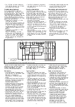
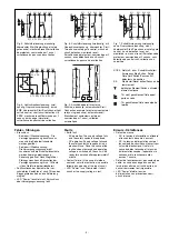
Gerätebeschreibung
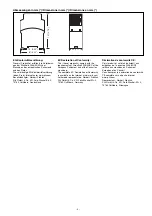
Das Sicherheitsschaltgerät PNOZ X4 ist in
einem P-97-Gehäuse untergebracht. Es
stehen verschiedene Gerätevarianten für
Wechselspannungen und eine Variante für
Gleichspannung zur Verfügung.
Standardausführung: 24 V DC
Merkmale:
• Relaisausgänge: 3 Sicherheitskontakte
(Schließer) und ein Hilfskontakt (Öffner),
zwangsgeführt
• Anschlussmöglichkeit für Not-Halt-
Taster, Schutztürgrenztaster, BWS,
Starttaster
• Statusanzeige
• Überwachung externer Schütze möglich
• DC: keine galvanische Trennung
• AC: galvanisch getrennt
Das Schaltgerät erfüllt folgende Sicherheitsan-
forderungen:
• Schaltung ist redundant mit Selbstüberwa-
chung aufgebaut (EN 954-1 Kategorie 4).
• Sicherheitseinrichtung bleibt auch bei
Ausfall eines Bauteils wirksam.
• Bei jedem Ein-Aus-Zyklus der Maschine
wird automatisch überprüft, ob die Relais
der Sicherheitseinrichtung richtig öffnen und
schließen.
Safety Regulations
• The unit may only be installed and
commissioned by a competent, qualified
electician or personnel instructed
accordingly,
who are familiar with both
these operating instructions and the
current regulations for health and safety
at work and accident prevention. Follow
VDE and local regulations especially
regarding preventive measures
• Transport, storage and operating
conditions should all conform to EN 60068-
2-6.
At the end of its lifecycle, dispose of the
unit in an environmentally safe way and
according to any relevant regulations
• Any guarantee is void if the unit is opened
or unauthorised modifications have been
carried out
• Adequate protection must be provided on
all output contacts especially with
capacitive and inductive loads.
• Note for overvoltage category III:
If voltages higher than low voltage
(>50 VAC or >120 VDC) are present on
the unit, connected control elements and
sensors must have a rated insulation
voltage of at least 250 V.
Intended Application
The safety relay provides a safety-related
interruption of a safety circuit.
The safety relay meets the requirements of
EN 60947-5-1, EN 60204-1 and VDE 0113-
1 and may be used in applications with
•
E-STOP pushbuttons
•
Safety gates
Description
The Safety Relay PNOZ X4 is enclosed in a
P-97 housing. There are different versions
available for AC operation and 1 for DC
operation.
Standard version: 24 V DC
Features:
• Relay outputs: 3 safety contacts (N/O)
and one auxiliary contact (N/C), positive-
guided.
• Connections for emergency stop button,
safety gate limit switch, ESPE and reset
button.
• Status indicators
• External contactor/relay monitoring
possible
• DC: No galvanic separation
• AC: galvanic separation
The relay complies with the following safety
requirements:
• The circuit is redundant with built-in self-
monitoring (EN 954-1 Category 4).
• The safety function remains effective in
the case of a component failure.
• The correct opening and closing of the
safety function relays is tested
automatically in each on-off cycle.
Conseils préliminaires
• La mise en oeuvre de l’appareil doit être
effectuée par une personne spécialisée
en installations électriques, en tenant
compte des prescriptions des différentes
normes applicables (NF, EN, VDE...)
notamment au niveau des risques
encourus en cas de défaillance de
l’équipement électrique.
• Respecter les exigences de la norme
EN 60068-2-6 lors du transport, du
stockage et de l'utilisation de l'appareil
(voir caractéristiques techniques).
Recycler l'appareil au bout de sa durée de
vie conformement aux prescriptions.
• L’ouverture de l’appareil ou sa modification
annule automatiquement la garantie.
• Vérifiez que le pouvoir de coupure des
contacts de sortie est suffisant en cas de
circuits capacitifs ou inductifs.
• Remarque relative à la catégorie de
surtensions III :
Si l’appareil est alimenté avec des tensions
supérieures à la basse tension (>50 V AC
ou >120 V DC), les éléments de
commande et les capteurs raccordés
doivent supporter une tension d’isolement
assignée d’au moins 250 V.
Domaines d’utilisation
Le bloc logique de sécurité sert à
interrompre en toute sécurité un circuit de
sécurité.
Le bloc logique de sécurité satisfait aux
exigences des normes EN 60947-5-1,
EN 60204-1 et VDE 0113-1 et peut être
utilisé dans des applications avec des
•
poussoirs d’arrêt d’urgence
•
protecteurs mobiles
Description de l’appareil
Inséré dans un boîtier P-97, le bloc logique
de sécurité PNOZ X4 est disponible en
différentes versions pour les tensions
alternatives et 1 version pour 24 V CC.
Version standard: 24 V DC
Particularités :
• Sorties disponibles : 3 contacts à
fermeture de sécurité et un contact à
ouverture pour signalisation
• Bornes de raccordement pour poussoirs
AU, détecteurs de position, barrières
immatérielles et poussoir de validation
• LEDs de visualisation
• Auto-contrôle possible des contacteurs
externes
• DC: pas d'isolation galvanique
• AC: d'isolation galvanique
Le relais PNOZ X4 répond aux exigences
suivantes :
• conception redondante avec auto-
surveillance (selon EN 954-1 cat. 4)
• sécurité garantie même en cas de
défaillance d’un composant
• test cyclique (ouverture/fermeture des
relais internes) à chaque cycle Marche/
Arrêt de la machine
19894-6NL-05
PNOZ X4
4
D
Betriebsanleitung
4
GB Operating instructions
4
F
Manuel d'utilisation
4
E
Instrucciones de uso
4
I
Istruzioni per l`uso
4
NL Gebruiksaanwijzing


