background image

Operation / Repair / Parts

Airless Line Striper

- For the application of athletic field line striping materials -

Model 867786

3000 psi (20.7 MPa, 207 bar) Maximum Working Pressure 

IMPORTANT SAFETY INSTRUCTIONS
Read all warnings and instructions in 
this manual. Save these instructions.

3A0441A

ENG

ti15263a

Summary of Contents for Brite Stripper 3000SP

Page 1: ...r the application of athletic field line striping materials Model 867786 3000 psi 20 7 MPa 207 bar Maximum Working Pressure IMPORTANT SAFETY INSTRUCTIONS Read all warnings and instructions in this manual Save these instructions 3A0441A ENG ti15263a ...

Page 2: ... Airless Spray Troubleshooting 19 Field Troubleshooting 20 Repair 21 Pail Bracket 21 Pressure Sensor 22 Pressure Control and Circuit Board 23 Drain Valve 24 Fluid Pump 25 Clutch 28 Gear Box 29 Drive Chain 30 Drive Assembly 31 Engine 32 Tires 34 Wheel Axle 35 Parts 36 Parts List 37 Gun Parts 42 Gun Parts List 42 Pump Parts 43 Pump Parts List 43 Pressure Control Wiring Diagram 44 Technical Data 45 B...

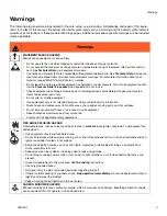
Page 3: ...t only for its intended purpose Call your distributor for information Route hoses and cables away from traffic areas sharp edges moving parts and hot surfaces Do not kink or over bend hoses or use hoses to pull equipment Keep children and animals away from work area Comply with all applicable safety regulations FIRE AND EXPLOSION HAZARD Flammable fumes such as solvent and paint fumes in work area ...

Page 4: ...ving parts Do not operate equipment with protective guards or covers removed Pressurized equipment can start without warning Before checking moving or servicing equipment follow the Pressure Relief Procedure and disconnect all power sources PRESSURIZED ALUMINUM PARTS HAZARD Use of fluids that are incompatible with aluminum in pressurized equipment can cause serious chemical reaction and equipment ...

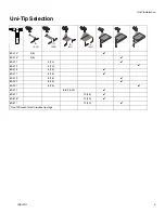
Page 5: ... Selection 69 213 2 5 69 215 2 5 69 217 4 10 69 219 4 10 69 315 4 10 69 317 6 15 69 319 6 15 69 321 6 15 69 327 6 15 69 417 6 8 15 20 69 517 10 25 69 615 12 30 69 617 12 30 Use 100 mesh filter to reduce tip clogs in cm in cm in cm in cm ...

Page 6: ...B A ti15264a N P R A Self Propel Engagement Lever B Spray Gun Control C Engine Throttle D Brake E Pressure Gauge F Prime Valve G Drain Spray Valve H Gun Trigger Lock J Engine Controls K Engine ON OFF Switch M Serial Identification Tag N Pressure Control P Cable Adjustment R Turn Control ...

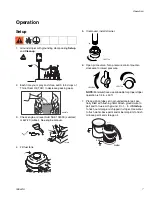
Page 7: ...Open prime valve Turn pressure control counter clockwise to lowest pressure NOTE Minimum hose size allowable for proper striper operation is 1 4 in x 50 ft 7 Place siphon tube set in grounded metal pail par tially filled with flushing fluid Attach ground wire to pail and to true earth ground Do 1 5 of Startup to flush out storage oil shipped in striper Use water to flush water base paint and miner...

Page 8: ... has not been fully relieved after following the steps above VERY SLOWLY loosen Uni Tip Guard retaining nut or hose end coupling to relieve pressure gradually then loosen completely Then clear tip or hose Startup 1 Perform Pressure Relief Procedure 2 Start Engine a Move fuel valve to open b Move choke to closed c Set throttle to fast d Set engine switch ON e Pull starter cord ti3306a ti5405a OFF O...

Page 9: ...ntil pump runs smoothly Inspect fittings for leaks Do not stop leaks with your hand or a rag If leaks occur turn striper OFF immedi ately Perform Pressure Relief page 8 Tighten leaky fittings Repeat Startup steps 1 2 If no leaks continue to trigger gun until system is thoroughly flushed Proceed to step 3 6 Place siphon tube in paint pail 7 Trigger gun again into flushing fluid pail until paint app...

Page 10: ...mly thread assembly onto gun Gun Placement 1 Install Gun Insert gun into gun holder with head guard pressed against the holder assembly bracket 2 Tighten gun into clamp 3 Position Gun Up down forward reverse left right NOTE Verify that the gun can still be triggered and that the trigger safety can still be engaged after installation Make adjustments if necessary To prevent injury when the gun is n...

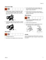
Page 11: ...dicular and approximately 12 in 304 mm from surface Move gun first then pull trigger to spray a test pattern 4 Slowly increase pump pressure until coverage is uniform and even see striper instruction manual for additional information Aligning Spray 1 Perform Pressure Relief Procedure page 8 Engage trigger lock 2 Loosen guard and retaining nut 3 Align guard horizontally to spray a horizontal pat te...

Page 12: ...nt pail Disengage gun trigger safety Gradually turn pressure control up until motor begins to drive pump Trigger gun until flush ing fluid appears 7 Move gun to flushing pail hold gun against pail trig ger gun to thoroughly flush system Release trigger and engage trigger safety 8 Open prime valve and allow flushing fluid to circu late for 1 to 2 minutes to clean drain tube 9 Raise siphon tube abov...

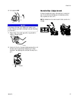
Page 13: ...ls Assemble parts and attach loosely onto gun Handle Bar Adjustment To adjust height and angle of handle bars loosen two nuts 147 and move handle bars to desired position Then tighten two nuts 147 NOTE Handle bars can be moved to down position for storage NOTICE If flushing with water flush again with pump condi tioner to leave a protective coating to prevent freezing or corrosion ti5405a OFF ON T...

Page 14: ...ct oil viscosity SPARK PLUG Use only BPR6ES NGK or W20EPR U NIPPONDENSO plug Gap plug to 0 028 to 0 031 in 0 7 to 0 8 mm Use spark plug wrench when installing and removing plug Swivel Wheel Stripers are factory aligned but if necessary loosen two bolts 128 on swivel wheel assembly just enough to be able to move the wheel by hand Align wheel and re tighten bolts Place turnbuckle 43 over the two mou...

Page 15: ...stem Packing life will be extended a minimum of three times if the proper packing tightening procedure is followed PACKING TIGHTENING PROCEDURE Inspect the packing nut daily If seepage of paint into the packing nut and or movement of the piston upward is found while not spraying the packing nut should be tightened enough to stop leakage only but not any tighter Grease Points Fill grease points at ...

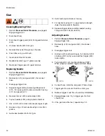
Page 16: ... clean internal passages of gun 8 Grease o rings of new needle using a non silicon grease 9 Guide new needle into front of gun 10 Install end cap and lockout loosely 11 For needle housing 411 apply medium strength blue thread sealant to threads 12 Squeeze trigger while installing needle housing Torque to 26 32 ft lb 35 43 N m Adjusting Needle 1 Perform Pressure Relief Procedure page 8 Engage trigg...

Page 17: ...right to avoid oil seepage Engine operates but fluid pump does not operate Pressure setting is too low Turn pressure adjusting knob clockwise to increase pressure Uni Tip or gun filter is clogged Clean Uni Tip or gun filter see gun man ual Fluid pump piston rod is stuck due to dried paint Repair pump see pump manual Connecting rod is worn or damaged Replace connecting rod page 29 Drive housing is ...

Page 18: ...ing nut Throat packing nut is loose See pump manual Throat packings are worn or damaged Replace packings See pump manual Fluid rod is worn or damaged Replace rod See pump manual Fluid is spitting from gun Air in pump or hose Check and tighten all fluid connections Reprime pump Uni Tip is partially clogged Clear Uni Tip See gun manual Fluid supply is low or empty Refill fluid supply Reprime pump Ch...

Page 19: ...le Thick skin of work Material too viscous Application too heavy Thin cautiously Reduce pressure and or use Uni Tip in next smaller nozzle group Coating fails to close and smooth over Material too viscous Thin cautiously Spray pattern irregular deflected Orifice clogged Uni Tip damaged Clean carefully Replace with new Uni Tip Craters or pock marks bubbles on work Solvent balance Use 1 to 3 short s...

Page 20: ...ssure valve bypassing Packings and or piston worn Turn up pressure Clean or replace gun filter Service outlet valve Clean or replace prime valve Tighten packing nut with tool Repack unit Unit does not maintain good spraying pressure Blown Uni Tip Packings and or pistons worn Upper seat worn Replace Uni Tip Repack striper Replace upper seat and ball Clutch does not engage Clutch failed Check resist...

Page 21: ...emove pail 103 2 Remove two screws 22 and remove pail bracket 88 NOTE The pail bracket is adjustable to fit different pail configurations Installation 1 Replace pail bracket 88 and tighten two bolts 22 2 Replace pail 103 ti15295a 22 88 ti15296a 22 88 ...

Page 22: ...o unscrew pressure sensor 209 from swivel fitting 216 6 Remove pressure sensor 209 Installation 1 Install new pressure sensor 209 and tighten onto swivel fitting 216 2 Feed pressure sensor wire through access hole in bottom of control box 13 Connect pressure sensor wire to control board 17 3 Replace control box cover 13 and use a small phillips screwdriver to tighten four screws 13 4 Replace pail ...

Page 23: ...n reconnecting or refer to Wiring Diagram see page 41 7 Remove circuit board and pressure control 17 Installation 1 Install new circuit board and pressure control 17 2 Single Engine Wire Models Replace grounding wire and tighten grounding nut and screw on board heat sink Double Engine Wire Models Reconnect wire s to circuit board and place wires back into control box 3 Install and tighten hex nut ...

Page 24: ... a wrench to loosen drain valve 113 and remove it from pump 211 Installation 1 Thread drain valve 113 into pump 211 opening 2 Hand tighten securely Use a wrench to tighten new drain valve into pump NOTE Tighten drain valve so fitting 119 will install from bottom 3 Replace fitting 119 and drain line 138 ti15311a 113 138 119 211 ...

Page 25: ... rod pin 8 Remove hose fittings and drain valve 113 9 Remove siphon tube hose assembly from fluid pump by unscrewing suction nut with packing adjustment tool NOTE When siphon tube 135 is removed from pump intake be sure to catch ball cage ball ball seat and o ring or they will fall to the floor Keep these pieces together in the same order 10 Use wrench to unscrew two bolts 128 from front cover ass...

Page 26: ...packing tool 311465 down through bottom of fluid pump body Lightly lubricate inside of the new packings with light weight oil or Throat Seal Oil 11 Replacing the Outlet Valve Parts a Place piston holder 331195 in a vise and slide piston into holder and lock in place with a 3 8 in dowel b Use a 1 4 in allen wrench to unscrew the outlet seat retainer 517f from the piston c Remove the outlet seat 517...

Page 27: ...on seat assembly o ring seat suc tion ball and suction ball guide in the suction nut and screw onto the pump body 7 On pumps with electronic pressure control recon nect the sensor to the pump body 211 Hold the sensor with a wrench while tightening the swivel fit ting 216 with an additional wrench 8 Start striper and operate slowly to check piston rod for binding Readjust the two bolts to eliminate...

Page 28: ...h housing on a flat surface and use two pry bars to evenly lift clutch off of shaft NOTE The clutch installs onto a square key Retain key when removing clutch Installation 1 Install key into shaft 2 Install edge grommet onto side of clutch orientation tab NOTE If the clutch is not installed correctly a loud rattle will be heard during operation 3 Align new clutch with keyway and push clutch 8U ont...

Page 29: ...tch ball cage ball ball seat and o ring or they will fall to the floor Keep these pieces together in the same order 4 Remove Pressure Sensor page 22 5 Remove Pump page 25 6 Remove Clutch page 28 7 Remove gear box 191 Installation 1 Replace gear box 191 2 Replace Clutch page 28 3 Replace Pump page 25 4 Replace Pressure Sensor page 22 5 Reconnect all hoses 6 Replace Pail Bracket page 21 ti15422a 191...

Page 30: ...chain guard cover 80 6 Slowly turn tire 86 by hand to rotate chain 78 and locate master link Disassemble and remove master link 7 Remove chain 78 Installation 1 Install new chain 78 and connect master link 2 Use a rubber mallet to tap engine bracket away from large sprocket 76 until chain is tight 3 Replace top chain guard cover 80 and tighten two bolts 22 4 Tighten four bolts 22 on engine bracket...

Page 31: ... assembly 300A onto drive shaft 56 2 Install woodruff key 300F onto drive shaft 56 3 Install pulley 72 onto drive shaft 56 and woodruff key 300F and install retaining clip 300D 4 Slide bearing 52 back onto shaft Note the orientation do NOT install backwards 5 Slowly turn pulley wheel by hand while pushing belt 81 onto large sprocket 72 to install belt 6 Replace drive assembly 300A and slide shaft ...

Page 32: ...set screws 8C and clutch adapter 8A Remove key 8F from shaft 7 Remove four hex nuts 8M and washers 8K between clutch housing and engine 8 Disconnect engine wire s Be sure to mark wires to refer to when reconnecting 9 Use wrench to remove four engine bolts 5 and remove engine 3 from engine mount bracket 1 Installation 1 Install new engine 3 into engine mount bracket 1 and use wrench to tighten four...

Page 33: ...engine 4 Install key 8F into shaft Replace clutch adapter and tighten three set screws 8C Clutch adapter plate should be 010 to 015 in from clutch 5 Replace Drive Assembly page 31 6 Replace Drive Chain page 30 7 Replace Gear Box page 29 8 Replace Pail Bracket page 21 ti15308a ti15377a 8K 8M ti15376a 8F 8A 8B 8C ...

Page 34: ...e nut 32 an additional 3 1 2 full turns Insert hairpin 87 through castle nut slots Castle Nut Adjustment Restrain opposite tire from turning while tightening nut with wrench If tires slip too much remove hairpin 87 and tighten castle nut 32 one notch clockwise If tires turn with too much resistance remove hairpin and turn castle nut 32 one notch counterclockwise Tire tension should be tested again...

Page 35: ...de water resistant grease to entire axle surface prior to assembly 1 Replace axle 75 as shown above 2 Replace shaft collars 250 and 251 and use wrench to tighten screws 3 Install sprocket key in axle as shown above Slide sprocket 76 on and use allen wrench to tighten two setscrews 4 Use grease gun to fill grease inlet until grease appears between axle and outer collars 5 Use straight edge to align...

Page 36: ...4 21 172 173 175 8J 8K 8M 168 8D 130 13 169 17 17 4 21 22 89 4 22 131A 131B 131C 131E 113 119 138 142 143 144 145 121 111 8V 139 8R 7 191F 191H 191D 191U 216 209 204 191N 191A 191B 191R 243 191K 206 191E 191S 191J 214 191G 191B 8S 8U 191U 191C 191A 189 18 13 205 191Q 211 131D 190 241 8Y 8C 8F 8N 8E 135 191M ti15329a ...

Page 37: ...CABLE throttle cable 1 142 121283 FITTING 1 4 mf x 45 degree 1 143 162453 CONNECTOR hose connect 1 4 nps x npt 1 144 156823 SWIVEL 1 4 NPT M F nps 1 145 116504 FITTING tee 1 4 npt M F F 1 168 331496 SCREW set 5 16 24 4 169 110637 SCREW 10 24 x 37 PN HD 6 172 867496 SCREW 1 4 20 x 1 00 HX HD 2 173 136217 NUT nut 1 4 20 jam ny lock st 2 175 100333 SCREW 1 4 20 x 50 HEX HD 4 184 342461 LABEL engine s...

Page 38: ... 300C 118 21 22 23 24 181 251 251 75 76 78 79 21 22 80 21 22 82 84 84 85 86 85 84 84 32 87 90 91 92 150 139 148 54 93 94 94 95 96 96 97 98 100 101 105 106 108 109 125 137 140 141 112 146 147 153 300 250 14 160 159 126 232 227 54 53 238 240 239 22 118 6 51 50 273 ti15330a See page 42 ...

Page 39: ...ly 1 96 111017 BEARING flange 2 97 116941 SCREW shoulder skt HD 1 98 116969 NUT lock 1 100 124134 TUBE cable 1 101 124133 SPRING compression 1 105 867125 CLAMP clamp 1 106 305108 PLATE plate 1 108 139353 ARM arm for sg short 1 109 143027 BALL ball glide 2 112 865674 HOSE paint hose 1 4 in x 50 ft 1 118 123979 HOOK hose 3 125 289316 GUN 500 4 finger ASM packaged 1 137 111145 KNOB pronged 1 139 3053...

Page 40: ...Parts 40 3A0441A Parts 138 236 54 237 21 48 45 271 50 39 25 26 30 29 31 29 32 33 34 35 36 36 36 36 37 38 38 49 40 41 42 41 44 46 47 51 229 272 50 51 128 27 28 88 21 22 104 136 103 135 220 ti15331a ...

Page 41: ...EW screw 3 8 16 x 5 SH CS 2 41 101566 NUT lock 4 42 C19837 SCREW cap socket HD 2 43 136231 TURNBUCKLE 12 1 4 max not shown 1 44 305258 LOCK swivel 1 45 136223 SPRING compression 48od 1 46 305257 PIN swivel lock 1 47 867007 FITTING grease ftg 1 8 27 1 48 305259 LOCK end lug lock 1 49 305141 ADJUSTER 8mm x 1 25 2 50 305089 INSERT cable 4 51 866047 CABLE assy 80 75 LG 1 52 123900 BEARING flange 2 bol...

Page 42: ...64 262 263 267 261 262 254 253 268 258 259 259 260 109 16 49 50 127 126 269 22 254 257 261 252 258 Ref Part Description Qty 401 288817 DIFFUSER SEAT KIT includes 1a 1b 1c 1 401a SEAT valve 1 401b NEEDLE 1 401c NUT lock 1 402 248200 GUARD tip 1 403 255126 TRIGGER 4 finger 288681 289284 1 404 195495 GUARD trigger 1 405 287099 SWIVEL gun 1 406 4433 2 FILTER mesh 50 white standard 1 4434 2 FILTER mesh...

Page 43: ...ING v packing 1 349 971 dia 6 508 331018 SPACER spacer 1 33 x 85 1 509 331019 HOLDER seal 1 510 331021 ADAPTER adaptor female 1 511 331022 ADAPTER adapter male 1 512 331023 PACKING v packing 1 064 687 DIA 3 513 331025 WASHER spring belleville 3 514 331029 RETAINER retainer 1 515 331030 BALL ball 500 gr100 1 516 331037 NUT packing 1 517 331093 PISTON assy lp rod 1 517a PISTON 1 517b PIN SPRING 1 51...

Page 44: ...LUTCH BLUE BLUE BLACK BLUE BLACK BLACK ti14817a Engine Single Wire Models Engine Double Wire Models Ref Part Description Qty 3 114530 ENGINE gas 1 13 305277 ENCLOSURE mach 1 17 865676 KIT control pressure includes 246 247 1 209 331294 SENSOR assy 1 246 117316 CONNECTOR bullet M 1 247 867095 CONNECTOR bullet F 1 248 24E873 WIRE control board 1 249 24E874 WIRE control board 1 248 3 3 246 247 246 247...

Page 45: ... screen reusable Outlet paint strainer 50 mesh 250 micron stainless steel screen reusable Pump inlet size 3 4 in npt m Fluid outlet size 1 4 npsm from fluid filter Wetted parts nickel plated carbon steel PTFE Nylon polyurethane UHMW polyethylene fluoroelastomer acetal leather tungsten carbide stainless steel chrome plating Model 867786 Weight dry without packaging Height Length Width 188 lb 85 2 k...

Page 46: ...Notes 46 3A0441A Notes ...

Page 47: ...Notes 3A0441A 47 Notes ...

Page 48: ...eplace free of charge any defective parts The equipment will be returned to the original purchaser transportation prepaid If inspection of the equipment does not disclose any defect in material or workmanship repairs will be made at a reasonable charge which charges may include the costs of parts labor and transportation Pioneer makes no warranty and disclaims all implied warranties of merchantabi...

Reviews: