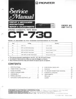
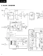
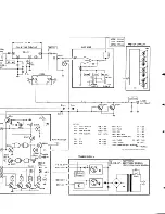
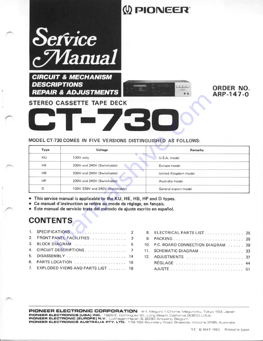
background image

Summary of Contents for CT-730

Page 1: ...I ELECTFIC NICB IUAAI lNC 1925 E Dom nguez St Long E each Ca ronnra 9OB1O U S A PIC NEEFI ELECTFIC NIC IEUFIC PEI N v Lu thagen Hsven 9 2O3O Antwe p Betg um FIC NEEFI ELECTFIG NICA AUATF ALIA PTY LTEI 178 184 Boundanv Fload E aesde V cto r6 3195 Ausr atia 8 ELECTRICAL PARTSLIST 9 PACKING 10 P C BOARDCONNECTION DIAGRAM 11 SCHEMATIC DIAGRAM 1 2 A D J U S T M E N T S REGLAGE AJUSTE 25 z 6 2S J5 37 44...

Page 2: ...V switchabtel 50 60H2 D modet AC12OV l22OVl240V switchabte 50 6OHz PowerConsumotion K U H E H B H P m o d e t s 2 S W D m o d e l 2 1 W Dimensions 420 W x 101 Hl x 235 D mm 16 9 16 W x 4 Hl x 9 t 4 Dl in Weig ht with ou tp ackag e 4 2kg 9lb4o zl Furnished Parts Operating instructions 1 Connection cord with pin plugg 2 NOTES 1 ReferenceTapes Normal LH DIN 4SE13 BLATT6 or eoulv CrO DtN 4Sb13 BLATTT ...

Page 3: ...ime preset on the audio timer and to start the playback The tape playback function can be used to wake up in the morning instead of an alarm clock For detailed instructions on the use of this function refer to RECORDING AND PLAYBACK USING THE AUDIO TTMER on page 10 oEJECT BUTTON Depress this button to open the cassette holder To close the cassetteholeer push the top back until it locks o Do not pr...

Page 4: ... to listen to and for creating the unrecorded blanks which are required for operating the MUSIC SEARCH facility o No signal are recorded when the switch is touched during recording Do not touch the switch unless necessary o REC MUTE O is display only but does not illuminate DPAUSE SWITCH Depress this switch to stop the tape temporarily during recording or playback Depress this switch again to allo...

Page 5: ...3 BLOCK DIAGRAM L I N E IN P U T REC PB Head r FLAT AMP t_ 20d8_l CONTROL CIRCUIT VR3OI EOUALIZER AMP Function Switch s i l o l B I A S C I R C U I T M P X F I L T E R 6b Qeog 5 ...

Page 6: ... O F F O N _ O F F O N _ O F F O N O F F O N O F F R E C O F F P L A Y ON OFF StlOl r ERASEPREVEIITO ECTOR HOLE N9_r9 E Thc undcrlrncd irdicatd thc sitch polrton r 1 SWITCHES S l O l I I N P U T S E L E C T O R S I 0 2 D O L B Y N R SIO3 TAPE SELEC OR SlO4 TAPE SELECIOR s t I F F 5602 REw s 6 0 3 s T o P IC60l Pin R E C A M P POWER SUPPLY METERCIRCUIT 120V 60Hz 22Ovl24OV50 60H2 120V1220V1240V50 60...

Page 7: ...t is adjusted by variable resistor Then after equaliza tion in the REC AMP IC403 in accordanceto the type of tape being used the signal is passed to the recording head B 4 3 CONTROL CIRCUIT The control circuit in this deck utilizes a one chip IC PM9002A which enables feather touch operations In addition to mechanism control this IC also includes music search MS auto stop and timer start functions ...

Page 8: ...F SOL being changed to H level 416ms later Q601 is thus turned on activating the FF solenoid to start fast forward operation 5 Rewind Mode When the REW button is pressed IC601 pin 7 RED is changed to L level followed by pin 25 REW SOL being changedto H level 416ms later Q602 is thus turned on activating the REW solenoid to start rewind operation 6 PauseMode The pause mode in this deck is released ...

Page 9: ... connected to pin 17 C318 continues to increase until it exceeds the threshold voltage The IC is thus switched to stop mode thereby stopping tape mechanisms 9 Timer Start Operation Timer recording timer playback and off modes are attained by changing the potential of IC601 pin 18 TIMER to Vcc ground and open respectively When a cassette tape with erasure prevention tabs intact is loaded ffid the P...

Page 10: ...mode Fig 4 4 Auto functionoperation o Timing Chart Normal operation M S O F F 1 a a tlU L a r H qtq H 3 4 oFF tc602 t 4 L I rceoz h PMgoo2A MUrE Key input M d T rrfi PLAY STOP FF STOP REIY STOP REC PAUSE PAUSE STOP REC STOP PAUSE PAUSE PLAY PAUSE t r I r l t L l r r o t u S T O P PLAY STOP F F STOP R E W STOP R E C STANO B R E C S T O P R E C STOP PAUSE STOP STOP P L A Y P A U S E LINE MUTE P i n ...

Page 11: ...n towards cam C due to operating lever spring B With cam C combined with cam gear D clockwise torque is applied to this cam gear Solenoid P is inactive and the hook of gear lever F is kept against stopper G of cam gear D by the cam gear return spring E thereby keeping cam gear D stationary The flywheel is belt driven by the capstan motor and rotates counterclockwise together with the capstan gear ...

Page 12: ...Q thereby tending to continue the rotationary motion of cam gear D but since stopper G catches the arm of gear lever F cam gear D stops rotating and operating lever A becomes stationary playback mode B Fig 4 10STOP PLAYoperation 3 o Operation of DifferentParts As can be seen in Fig 4 10 ttre head base drive pin of operating lever A rises during play back mode This pin forces the head base up throu...

Page 13: ...g in rotation of the supply reel base At the same time the pin at the tip of the drive arm pushesthe brake plate up thereby releasingthe reel brake Brakeplate Brakeshoe SofenoidR I I Brakeshoe Supplyreelbase Brakeplate Drivearm Fig 4 14 Rewind operation MS Operation MusicSearch MS operation involves combination with fast forward and rewind operations similar to cue and review operations At the beg...

Page 14: ...5 DISASSEMBLY o 8 I I I zI q I I I Sub panel base Door assembly Mechanism assembly F3 _t 0tl laI iL R Fig 5 1 Disassembly ...

Page 15: ...he REC VR knob and the two screws below and gently press down on hook with a screwdriver so the front panel can be pulled loose 5 Unscrew the front panel base screws l and remove the front panel base 6 Remove the mechanism assembly by removing the door assembly and unscrewing screws 7 Remove the panel stay by unscrewing screws O removing the connecting plate and unscrewing screws FrontPanel 1 Remo...

Page 16: ... your Parts Stock Control the fast mouing items arc indicated uith the marhs and T GENERALLY MOWS FASTER THAN 1 This clossificotion sholl be od justed by each distributor because it depends on model number temperature humidity etc Eonnet RNA 576 Front panel RN L 472 Knob Function RAC 239 MICjack RNK 073 Knob MSl RAC 235 KnobB Tape selector RAC 237 KnobA Tape selector RAC 236 Front panel base R N L...

Page 17: ...y RXM 076 A Powerswirch i J Capstan belt R E 8 4 1 1 Plunger solenoid F R X P 1 1 7 RXp l14 I KU tYPe iiir_l r I HE HB HP D types RSA 055 KU typ l RSA O47 HE HB HPtypesl RSA Os7 D type A Plunger sol noid R ffil t tu r f lit HE HB HP Dtvpes RearPanelView Terminal LlNEl RK8 Ot 8 Foot assembly REC 369 3 s0jack RKN 071 RDG 022 RDG 030 RDG 036 RDG O32 RDC O29 RDG O39 KU typ HE type HB type HP type D ty...

Page 18: ... switch assembly Heatsink Connector assembly 2P Connector assembly 6P Knob A Tape selectorl Knob B Tape selector Wier nut Power transformer 120V KU type Power transformer l22OVl24OV HE HB HP typesl Power transformer n2OV l22OV 1240V D type Capacitor KU type Capacitor HE HB HP types Capacitor D type Powerswitch KU type Power switch HE HB HP types Power switch D type Knob Power Power cord KU type Po...

Page 19: ...Relayterminal HE HB HP types Line voltage selector switchable2 positions 22OVl24OV HE HB HP types Line voltage selector switchable3 positions 12OVl22OV l24OV D type 81 VCZ30P080FMC 82 VBZ30P080FMC 83 PMZ30P060FMC 84 1 REK 064 84 2 REK O48 Schrew HE HB HP types Screw HE HB Hp types Screw Fuse 80OmA HE HB HP rypes Fuse 0 5A D type A A 52 2 54 2 ...

Page 20: ...3 2 J A 1 Exterior For KU type h 1 N B t3 14k J too l 0lt I lS Jrlthll lil Ql Inl l te q 68 C A r 65 66 D 3 2 1 N oN o 65 68 5 N ...

Page 21: ...4 5 A hr i ru B C D 6 5 4 21 I ...

Page 22: ...3 2 1 A 73 v B orffi or l e Nl t4 i C D 1 3 2 ...

Page 23: ...L A 6 5 4 in ry jI fl 8ffi1 qUe ss ffi 1 4Z 79 B r i1 s 7e f 6 C i 1 u D l 6 5 4 a i 49 ry t ...

Page 24: ... HB HP D types Plungersolenoid F KU typel Brake shoe Shaft stopper Supply reel baseassembly 46 47 48 49 50 5 1 52 53 54 55 56 57 58 59 60 6 1 62 63 64 65 RNK 999 RNK 998 RX8 360 RNL O59 RXB 541 RX8 378 RBH 725 RXB 374 RAH 724 RX8 376 REB 446 RXM O76 RXB 5OO RXB 358 REB 411 RBF O51 RBH 721 RNL 397 RNL O58 PMZ2OPOSOFMC vc226P090FMC ATZ26P06OFzK PMZ2OPl30FMC PMZ2OPl2OFMC PM226PO3OFMC vc226P060FMC YE3...

Page 25: ...her 102 R84 076 103 RNH 989 to4 RE8 440 Specialscrew Spacer Stopper RWX625 RWX626 RWG 135 MainAssembly RWX 25 KU D types RWX 26 HE HB HPtypes CAPACITORS Mark Part No Symbol Description Main assembly KU D types Main assembly HE HB HP types Control assembly DOLBY NB switch assembly Timer switch assembly Volume assembly Sensor assembly Meter assembly Symbol Description OTHERS Mark Part No ccDSL 331K ...

Page 26: ...sistanceualue into code form and then rewrite the part no as before Mark PartNo Symbol Description A A A A A RCP l50 RCP l95 RCP l49 RCP 1931 RCP l55 RCP 2001 RM5 10 UB RSlPF82OJ RD PSF 471J RD PSF 1O2J RDz4PM trtrtr J SEMICONDUCTORS Mark Part No VR1O2 VR202 Semi fixed 22k Bl VR103 VR203 VR401 Semi fixed 10k B VR301 VR302 Semi fixed 150k B R141 R142 R241 R242 P 217 R309 R301 R228 R308 R101 R103 R1...

Page 27: ... RSG 131 5608 Push switch into code form and then rewrite the part no as before Mark PartNo OTHERS Mark Part No SYmbol Description RELO94 PL6O1 PL602 LamP PR5724S LED6O1 BG5724S LED602 DOLBYNR SwitchAssemblY Mark Part No Svmbol Description RSG 131 5102 Push switch TimerSwitchAssembly Symbol Description HSHO64 5901 Slideswirch VolumeAssembly Mark Part No Symbol Description RCV 99 VR8O1 Variable 20k...

Page 28: ... B Connection cord A Spacer 2SA933LN 2SC1740LNf lr rype No s rr Fri 1 n j r ott to il J tl 2SA937 2siq2021 Itrr D l 0 o lTTfT n UU U 2SA1015 2SC1815 2s C2240 Type No Type No Lot No 2SD837 HDltl011B TC4011BP MB8 IOl1BM HD140668 TC4066BP MB8 O66BM HA11226 8A328 1 2 3 4 5 6 7 8 RHG 52O RHG521 RHG 522 RHG 523 RHA 244 RRB 177 RREO22 RRB 178 RRD O58 RHX03l RDE O63 RDE 64 RDE 65 RHC l38 2SA1127NC 2SC2634...

Page 29: ...10 P 1 C BOARDS lrl CONNECTIONDIAGRAM A oroaF rctot H Icaol o2o2 o2o3 QlOl B c DOLBY SWITCH Ass y VOLUME AssY 3e ffi D 2 1 l ...

Page 30: ...i 0u o KD oi F J 11 1t 1e ero3 i jl li iil 15 r l 1 i Fk fil rX J J l l L r b 0 nt o r 3 o r rfi il a v az 2 jrinr 1 a i 4r r g i 1u r i F lfi j v s Ll 1 T 1 9 11 T oofi To oot _ t t 1 1 1_ 1_ f r fl r E f i J gF Ti j X _ I i l r f c oooai y7 d tr rj S 1 K1fl h5 t Y e t e h 1 Itr rj t 1 i t I i o i H F ss n ff F r l ti E L r l u i rl t r rl l l 5 r1 r e itrA h rffi ii i f tril f ri 5i 5 E s I d j ...

Page 31: ...I 8 7 l cro0 0 0rlac250 METER A J l CONTROL Ass sLr sL2 SL3 SL4 FF REW PINCHMS sol soL soL soL I 8 7 L ...

Page 32: ...12 11 10 A B c srt0r ERASE PREVEI I DETECTOR SENSOR Ass y D TIMER SWITCH Ass t_ METER Assty 11 12 ...

Page 33: ... R532 2 2 r A IC1O2 qio5 2O5 TC4055aP 2SCi740LN or M864O668M o 2SCtOtg or HOi4O66B or 2SC2O2 swrrcHtNc or 2SC2634 C F L A TA M P B REC P A H E A O 50 I ERASE 2 I BEAo x t p I w I n a oes U T 9 o c r o o l 2030r wz 135 20302 wz 120 20305 Bz o50 c 3 r 3 Q 3 O 3 3 O 8 3 1 1 2SA9 37 o r 2 S A 9 3 3 L N or 25A1Ol5 or 2SAll27NC D Q 3 O l 3 O 2 2 S D A 3 7 or 2501O31 REGULATOF O3O5 306 315 D3O7 3O9 1SR35...

Page 34: ...2l or 2SC2634NC SWITCHING L80602 9G572 D605 6O 1s2473 or uslo4r f I l ii q 3 o 3 3 O 8 3 r l 2SAI 37 o r 2 3 A 9 3 3 L N or 2SAlOl5 or 2SAll27NC A 6 5 4 6r le6 rrc xa tl Q1O7 108 207 2OA M U T I N G R2a6 c2ta Faag l i j R E C O N Q307 c3ro 2SCl74OLil o 2SC10t5 loo f6 or 2SC2O21 or 2SC2634NC D 3 l l 3 1 4 F524 152473 2 2 o r U s l o 4 o q3o4 306 2SCr74OLi q3O6 SWITCHING REC ON I M U T I N G Q J r r...

Page 35: ... it t rhe A mark tound on some componenr parts indicares the im podance of the sfety factor of the pan Therefore when replacing be re to use Fns of idenlicai designation Thh is the basic shemaiic diagiam bul rhe actual circuii hay vary due to rmprovemenis in design c2 a R2a9 D3il 314 152473 or USI O4O 5 I FF s 5 0 2 R E W s503 sToP 5604 PLAY 5605 PAUSE s606 REC 5607 REC MUTE s608 i MUSTC SEARCH MS...

Page 36: ...ue ones only Other alternative semiconductors may be used and are listed in the Parts list POWEF SUPPLY CIRCUIT FOR HE TYPE o For HE HB HPtypes POWEF SUPPLY CIRCUIT FOR H8 TYPE POWER SUPPlY CIRCUIT FOR HP TYPE POWEF SUPPLY CIRCUIT FOR D TYPE D 11 A l L 10 12 l ...

Page 37: ...se ranges replace the supply reel assembly pa no RXB 377 take up reel assembly part no RXB 360 or the full drive arm assembly part no RXB 376 Table1 TU reel baseass y Supply reel baseass y Playback mode 35 55g cm 2 Sg cm Farst forward mode 75 11Og cm 2 Sg cm Rewind mode 2 Sg cm 75 110g cm NOTE denotes bach tension torque 37 12 1 3 Tape SpeedAdjustment 1 Connect a frequency counter to the PLAY term...

Page 38: ... Adjustment 1 Put the deck into rewind mode 2 Loosen screw and adjust the mounting position of the REW solenoid plunger solenoid R so that the square hole in the full reel base a ssembly is flush against the boss of the full drive arm assembly See Tig L2 4 FF position Contacting TU idler ldlergear Supplyreelbase assembly FF solenoid plunger solenoid F ldlergear TU reelbase assembly ldlergear I FF ...

Page 39: ...ack level 4 Playback equalization check 5 Level meter check 6 Record playback frequency response 7 Recording level 3 4 STD 341A STD 608A STD 6O3 STD 604 Playback adjustments NORMAL blank tape CrO2 blank tape METAL blank tape Prepare the following measuring equipment AC millivoltmeter audio oscillator attenuator and oscilloscope Unless otherwise specified always adjust for both left and right chann...

Page 40: ... NORM Mode Playback o o I N P U T V F V R 4 0 I E q I o N T P I L c h T P 2 R c n e o 2 2dBv 775mV 7 9 d B v l 2 7 m V aecneaa tl 2kt1z I0dBv 3l6mV o I 30dBv 3 1 6 n V Fig 12 7 DOLBY NR leveladjustment Procedure L Acijust the INPUT level control so mV meter reads 2 2dBv 776mV 2 Drop the input signal level to attenuator and switch the Dolby oN 3 Adjust VR401 so that the meter dBv 127mV 12 2 2 HeadA...

Page 41: ...pe selector to METAL play the 333H2 20d8 portion again and record the meter reading 4 Then play the 6 3kHz 20dB portion again and check that the meter reading lies within 2 511dB of the reading obtained in step 3 Connect to OUTPUT ter minals STD 341A 333H2 20dB 6 4W12 20dB NORM Playback 12 2 5 LevelMeterCheck Settings AC mV meter Connect to TP1 L ch and TP2 R ch Input signal 333H2 10dBv 316mV to I...

Page 42: ... tape STD 608A Tape selector NORM DOLBYNRswitch ON t O t H r Tasttape STD 603 Tapeselector CrO2 DOLBYNRswitch OFF 333H2 30dBv 3l OmV 6 3kHz JU6V 3l 6mV B 3k Hz level 333H2 level O 5dB Fig 12 13 Record playback frequency response adjustment Procedure 1 Adjust the INPUT level control so that the meter reads27dBv 4a 6mV 2 Record the 333H2 30dBv and 6 3kHz 30dBv signals and adjust VR301 L ch and VR302...

Page 43: ...r 3r6nV Tast tape Tape selector DOLBY NR switch Fig 12 15 Recording leveladjustment Procedure Adjust the INPUT level control so that the meter reads 5 2dBv 549mV Switch the DOLBY NR switch ON Record the 333H2 10dBv signal on the STD 608A test tape Then adjust VR103 L ch and VR203 R ch so that the meter reads of 5 4dBv 549mV when the recorded signalis played back Switch the tape selector to the CrO...

Page 44: ...sont inf6rieures re mplacer I ensemble du rouleau d alimentation 6l6ment No RXB 377 enlever I ensemblede rou leau 6l6ment No RXB 360 ou I ensembledu bras d entrainement 6l6ment No RXB 376 REMARQUE montreuncoupledetension deretour 12 1 3 R6glagede la vitessede d6filement de la bande 1 Brancher un mesureur de fr6quence aux bornesde PLAY 2 Faire lire la portion de SkHz de la bande d essai STD 301 Au ...

Page 45: ...en mode de rembobi nage 2 D6sserrer la vis 2 et ftgler la position de mon tage du sol6noide de REW sol6noide de plongeur R de telle sorte que le trou carr6 de I ensemble de rouleau de base touche I embos sement de I ensemble du bras d entrainement voir Fig 12 a SystCmede base ensembledu brasd entrainement Position de rebobinage REW Support de bobine ddrouleuse Contre abestan Contrecabestan Positio...

Page 46: ...roc6der en suivant la s6quence sp6cifi6e de r6glage Un changement dans la s6quencepeut empGcher un r6glage correct d 6tre fait et peut produire pil la suite une perte de qualit6 Sdquence der6glage 1 Niveaude DOLBY NR 2 Azimuth de t6tes 3 Niveau de lecture 4 V6rification du filtrage de lecture 5 V6rification du niveau de mesureur 6 R6ponse de fr6quence enregistrement lecture 7 Niveau d enregistreme...

Page 47: ...Bv 316mV a I 30dBv 31 6mV MillivoltmdtreAC Bande d essai S6lecteurde bande Mode VR102 et VR202 Brancher sur les bornes de sortie STD 341A 10kHz 2OdB NORM Lecture Tourner vers la droite pour position maximum TPI can8l gauch TP2 canal droir Fi1 12 7 Rdglage du niveau de DOLBY NR Marche i suivre 1 Ajuster le contr6le de niveau d entr6e de telle sorte que le millivoltmdtre AC indique 2 2dBv 776mV 2 Fa...

Page 48: ...te faire marcher la portion de 6 3kHz 20d8 et v6rifier que les indications du mesureur sont proches de 1 5 tzdB de la lecture faite en 1 ci dessus 3 Commuter le s6lecteur de bande a METAL faire marcher e nouveau la portion 333H2 20dB et enregistrer I indication du mesureur 4 Ensuite repasserla portion 6 3kHz ZOdB et v6rifier que les indications du mesureur sont proches de 2 5 1dB de la lecture fai...

Page 49: ...8A S6lecteurdebande NORM Commutateur de DOLBY NR OFF Bande d essai STD 608A S6lecteurdebande NORM Commutateur de DOLBY NR ON Bande d essai STD 603 S6lecteurde bande CrOz Commutateur de DOLBY NR OFF a niveau 333H2 n v6ss 0 5d8 Fig 12 13 R6glage de r6ponse defr6quence enreg istre ment ecture Marched suivre 1 Ajuster le contr6le de niveau d entr6e de telle sorte que le mesureur indique 27dBv 44 6 mv ...

Page 50: ...S6lecteurde bande Commutateur de DOLBY NR 333kHz 1OdAv 3l6mV Fig 12 15 R6glage du niveau d enregistrement Marched suivre 1 Ajuster le contr6le de niveau d entr6e de telle sorte que Ie mesureur indique 5 2dBv 549 mv 2 Commuter le DOLBY NR ON 3 Enregistrer le signal de 333H2 10dBv sur la bande STD 608A Puis ajuster VR103 canal gauche et VR203 canal droite de telle sorte que le mesureur indique 5 4dB...

Page 51: ...te de arrastre parte no RXB 360 o ensamble del brazo impulsor parte no RXB 376 Tabla1 Conjunto de la base del carrete de arrestre Conjunto de la base del carrete de suministro Modo de de reproducci6n 35 55g cm 2 Sg cm Modo de de avancerdpido 75 11Og cm 2 5g cm Modo de de rebobinado 2 5g cm 75 110g cm NOTA indicapar de torsi6n de contratensi6n 12 1 3 Ajuste de la velocidadde la cinta 1 Conectar un ...

Page 52: ... magnet6fono en el modo de rebobinado 2 Aflojar eI tornillo 2 y ajustar la posici6n de montaje del solenoide de REW solenoide de nircleo m6vil R de modo que el orificio cuadrado del ensamble de la base del carrete quede empotrada en el saliente del ensamble del brazo impulsor ver la Fig L2 4 Cubo conjunto completo del brazo impulsor Posici6nREW Poeici6nFF Conjunto de la basedel carrete de suminist...

Page 53: ... y de grabaci6n 9 Proceder de acuerdo con la secuencia de ajuste especificada Si se cambia la secuencia se puede ocasionar el ajuste incorrecto dando como resultado en una p6rdida del rendimiento Secuencia deajuste 1 Nivel Dolby NR 2 Acimut de la cabeza 3 Nivel de reproducci6n 4 Comprobaci6n de Ia ecualizaci6n en repro ducci6n 5 Comprobaci6n del medidor del nivel 6 Respuesta en frecuencia de graba...

Page 54: ... q I o Interruptoroolby NFI o N IP TP canal izq c a n a l d e r l 4 e o 2 2dBv 776mV 17 9dBv 127mV Cab za de f grabacion I e 2kHz 1OdBv 3 1 6 m V o J 30dBv 31 6mV Fig 12 7 Ajuste delnivel DOLBY NR Procedimiento 1 Ajustar el control del nivel de entrada INPUT de modo que el milivoltfmetro de CA indique 2 2dBv 776mV 2 Reducir el nivel de la sefral de entrada a 30 dBv con el atenuador y poner el inte...

Page 55: ...ci6n del voltfmetro est6 entre 1 5 a 2dB de la indica ci6n obtenida en el paso 1 anterior 3 Poner el selector de cintas en la posici6n de METAL reproducir la parte de BBBHz 2OdB de nuevo y registrar la indicaci6n del voltf metro 4 Entonces reproducir de nuevo la parte de 6 8 kHz 20d8 y comprobar que la indicaci6n del voltfmetro est6 entre 2 5t 1dB cle la indicaci6n obtenida en el paso B Fig 12 12 ...

Page 56: ... ajustar el VR30l canal izq y VR302 canal der de modo que la diferencia en el nivel de la sefralde salidade reproducci6n con el nivel de 333H2 como nivel de referencia sea 0 5dB 3 Cambiar las posiciones del selector de cintas e intermptor DOLBY NR ver la figura 13 10 y comprobar que la respuestaen frecuencia sea satisfactoria 56 Respuesta en frecuenciade reproducci6n Cinta de preuba STD 34LA Selec...

Page 57: ...o indique b 2dBv 549mV 2 Poner el interruptor DOLBY NR en la posici6n oN 3 Grabar la sefralde 3BBHz 10dBv en la cinta de prueba STD 608A Entonces ajustar el VR103 canal izq y VR20B canal der de modo que el voltfmetro indique b 4dBv 549mV cuando la sefral grabada se repro duzca 4 Poner el selector de cintas en la posici6n de CrO2 y repetir el paso B empleando la cinta de pmeba STD 608 El nivel de s...

Reviews: