background image

Summary of Contents for LD-V8000 Level I

Page 1: ......

Page 2: ...yers manufactured after that date with the serial numbers above KJ3906076 contain software modifications on EPROMS DYW 1119 DYW 1120 and above The LD V8000 version upgrade player returns the model name P150604 when queried under external computer control An EPROM Upgrade Kit is available for customers with LD V8000 s manufactured before October 17 1990 Since then there have been several running EP...

Page 3: ... Title Company Address City State Zip Phone Date Comments Please return this registration form and any comments to Pioneer New Media Technologies Inc Technical Support and Systems Integration 2265 E 220th Street Long Beach CA 90810 PHONE 310 952 2111 FAX 310 952 3031 LD V8000 Level I III User s Manual TP 113 v 2 1 5 96 ...

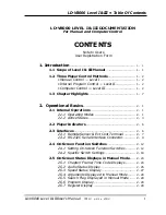
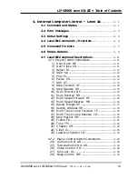
Page 4: ...3 1 Remote Sensor Ext Cont Terminal 2 7 2 3 2 RS 232C Serial Interface Connector 2 9 2 4 On Screen Function Switches 2 12 2 4 1 Setting On Screen Function Switches 2 12 2 4 2 Specific Switch Settings 2 18 2 5 On Screen Status Displays in Manual Mode 2 24 2 5 1 Chapter Frame Time Code Displays 2 24 2 5 2 Audio Status Display 2 25 2 5 3 Speed Status Display 2 27 2 5 4 Arguments Displayed in Manual M...

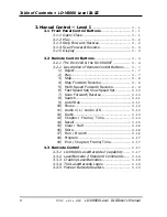
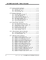
Page 5: ... Speed Set Slow Speed Set 3 10 7 Scan Forward Reverse 3 10 8 Search 3 11 9 Auto Stop 3 11 10 Pause 3 12 11 Audio 1 L Audio 2 R 3 12 12 Audio 3 13 13 Chapter Frame Time 3 14 14 Recall 3 15 15 Clear Halt 3 16 16 Store 3 16 17 Run Branch 3 16 18 Program 3 17 19 End Chapter Frame Time 3 17 3 3 Barcode Control 3 17 3 3 1 LD V8000 LaserBarcode 2 Capability 3 17 3 3 2 LaserBarcode 2 Standard Commands 3 1...

Page 6: ...everse SR 4 15 10 Scan Forward NF 4 15 11 Scan Reverse NR 4 15 12 Multi Speed Forward MF 4 16 13 Multi Speed Reverse MR 4 16 14 Speed Integer SP 4 17 15 Search Address SE 4 18 16 Multi Track Jump Forward JF 4 19 17 Multi Track Jump Reverse JR 4 19 18 Stop Marker SM 4 20 19 Frame FR 4 21 20 Time TM 4 22 21 Chapter CH 4 22 22 Clear CL 4 23 23 Lead Out Symbol LO 4 23 4 7 2 Player Control Switch Comma...

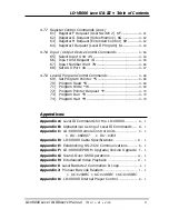
Page 7: ...45 44 Select Playback Field IM 4 46 4 7 6 Communication Control Commands 4 47 45 Communication Control CM 4 47 46 CCR Mode Request M 4 47 4 7 7 Register Control Commands 4 48 47 Register A Set Display RA 4 48 48 Register B Set Squelch Control RB 4 51 49 Register C Set Miscellaneous RC 4 52 50 Register D Set RS 232 Parameter RD 4 53 51 Register E Set User s Switch 1 RE 4 54 52 Register F Set User s...

Page 8: ...am Pointer S 4 68 70 Program Read D 4 68 71 Program Write W 4 69 72 Program Pointer Request P 4 70 73 Program Run R 4 70 74 Program Halt H 4 70 Appendices Appendix A Level III Commands for the LD V8000 A 1 Appendix B Alphabetical Listing of Level III Commands B 1 Appendix C LD V8000 Remote Control Units C 1 RU V6000T RU V103 Appendix D LD V8000 Cable Specifications D 1 Appendix E Establishing RS 2...

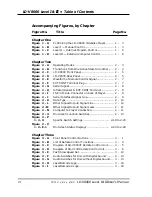
Page 9: ...T Terminal 2 8 Figure 2 I 15 Pin D Sub Connector on back of Player 2 9 Figure 2 J Serial Interface Signal Line 2 9 Figure 2 K Data Type 2 10 Figure 2 L Other Signal Output Signal Line 2 10 Figure 2 M Other Signal Output Signal Level 2 11 Figure 2 N Computer to Player Connection 2 11 Figure 2 O On Screen Function Switches 2 13 Figure 2 P to 2 U Specific Switch Settings 2 18 to 2 23 Figure 2 V to 2 ...

Page 10: ...4 J Audio Control Register Settings 4 26 Figure 4 K Audio Switch Diagram 4 27 Figure 4 L Video Control Diagram 4 28 Figure 4 M Display Control Diagram 4 31 Figure 4 N Character Code Table 4 33 Figure 4 O Player Active Mode Request Codes 4 36 Figure 4 P Video Memory Frame Mode Diagram 4 40 Figure 4 Q Video Memory Field Mode Diagram 4 41 Figure 4 R Interleaved Video Playback Program Example 4 46 Fig...

Page 11: ... 1 1 Scope of Level I III Manual 1 2 Three Player Control Methods 1 3 Chapter Highlights LD V8000 LEVEL I III USER S MANUAL Programmer s Reference Guide 1 CHAPTER LD V8000 Level I III User s Manual TP 113 v 2 1 2 93 ...

Page 12: ...evel III command set to make interleaved video playback possible See Chapter 4 and Appendices G and H for details Other features that set the LD V8000 player apart are Four channels of audio output two analog and two digital an internal composite sync generator for syncing multiple players together two video output signals for playback on two monitors simultaneously built in LaserBarcode capabilit...

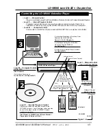
Page 13: ...cations A Level I system consists of a videodisc player and a monitor It is controlled by using the front panel buttons on the player a remote control unit or a Pioneer Barcode Reader Level I is used mainly for playing videodiscs continuously for simple searches for searching to a specific series of frames and stepping through them or for playing discrete motion video segments Level II systems are...

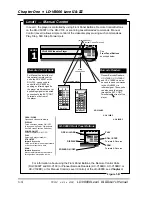
Page 14: ...e player via the infrared sensor on the front panel See Section 3 2 LEVEL 1 Infrared Sensor External Control Terminal LD V8000 Level I III Chapter One LD V8000 Level I III User s Manual TP 113 v 2 1 2 93 1 3 Level I Manual Control Player is controlled using Front Panel Buttons Remote Control or Pioneer Barcode Reader Level II Internal Program Control Programs loaded into player s memory from data ...

Page 15: ...e units can also send the signal through the EXT CONT Terminal on the front of the player Remote Control Units Barcode Readers UC V104BC LEVEL 1 wired connections Infrared signal Infrared Sensor External Control Terminal OPEN CLOSE DISPLAY POWER ON OFF PLAY STILL STEP Forward Reverse SCAN Forward Reverse LD V8000 Front Panel Buttons In Level I the player is controlled by using Front Panel Buttons ...

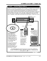
Page 16: ... programs can also be sent directly to the LD V8000 s memory for demonstration and test purposes via the player s RS 232 connection 0 2 5 6 7 8 9 1 3 4 RU V6000T For detailed information about Internal Program Control of the LD V8000 see Pioneer s LD V8000 Level II User s Manual Programmer s Reference Guide TP 114 Ver 1 1 8 92 OR OR LEVEL 2 Infrared Sensor External Control Terminal wired connectio...

Page 17: ...tached to the player s RS 232C port The Level III mnemonic command set is used to develop interactive programs for the LD V8000 See Appendix A for the list of mnemonic commands available on the LD V8000 Level III mnemonic commands are also used to control the LD V4400 CLD V2400 LD V2200 LD V4300D and the discontinued LD V4200 Level III is used when a program designer wants users to have access to ...

Page 18: ...gnals and the RS 232C serial interface connector There is also a detailed section about On Screen Function Switches On the LD V8000 the function switches are set on screen rather than with dip switches as on previous players The last section describes the On Screen Status Displays Chapter Three Manual Control Level I This chapter describes the player s front panel buttons the remote control button...

Page 19: ...vel III Player Control Appendix F LD V8000 EPROM Upgrades 1990 Version Upgrade Appendix G Sound Over Still Operations Appendix H Interleaved Video Playback Appendix I LaserBarcode 2 Commands Logo Appendix J Using Pioneer Barcode Readers UC V104BC UC V108BC UC V109BC Appendix K LD V8000 Internal Player Control Further questions should be referred to Pioneer New Media Technologies Inc Phone 310 952 ...

Page 20: ...ns 2 2 Player Indicators 2 3 Interfaces 2 4 On Screen Function Switches 2 5 On Screen Status Displays in Manual Mode LD V8000 LEVEL I III USER S MANUAL Programmer s Reference Guide 2 CHAPTER LD V8000 Level I III User s Manual TP 113 v 2 1 2 93 ...

Page 21: ...ic Mode Program Mode Register Mode These modes are defined as follows 1 Normal Control Mode When the LD V8000 player power is turned on the player enters Normal Control Mode In this mode the player can be controlled by pressing buttons on the front panel of the player by pressing buttons on the remote control unit by sending commands via a Pioneer Barcode Reader or by sending commands from a compu...

Page 22: ...Function Switches The operating mode of the player changes from Automatic Mode to Normal Control Mode when a HALT command is executed 5 Program Mode In Program Mode a Level II program is written and modified in memory Press the PROGRAM button on the RU V6000T remote control unit or send commands from a computer via the RS 232C when the player is in Normal Control Mode to make it enter Programming ...

Page 23: ... 2 3 Normal Control Mode using P O W E R O N R E M O T E C O N T R O L R S 2 3 2 C Function Switch Setting Mode Press DISPLAY again to commit settings to memory and to exit Function Switch Setting Mode Test Mode Select Test Mode on P 2 of Function Settings or Turn ON 1 Bit 7 of Reg C Not required for normal player operation used primarily for servicing the player REG C BIT 7 1 REG C BIT 7 0 Simult...

Page 24: ...Speed Sound Over Still etc are possible only when the player is in Random Access When a REJECT command is input the player enters Spin Down image playback stops immediately and disc rotation is gradually stopped then the player enters Park The Figure 2 B below describes how the active states change within the player Chapter Two LD V8000 Level I III 2 4 TP 113 v 2 0 2 93 LD V8000 Level I III User s...

Page 25: ... terminals are only for connection to color video monitors monitors with a video input terminal They provide an NTSC video signal They are not for connection to conventional TV sets The player can output video to two monitors simultaneously ANALOG AUDIO OUT Terminals RCA Jacks These two terminals output only the analog audio of LaserVision discs Connect them to the AUX input terminals of your ster...

Page 26: ...s Mode and a search is not being executed It blinks when the the player is in Spin Up Spin Down or Random Access Mode and when the lead in or lead out area is reached Search Indicator green The Search Indicator lights up only when the player is searching Key Lock Indicator red The Key Lock Indicator lights up if a command has been sent to the player to lock the front panel control buttons preventi...

Page 27: ... KHz carrier removes the carrier shapes the waveform and outputs the shaped waveform See Figure 2 E The stereo mini plug Figure 2 F is used to input a signal to the EXT CONT terminal providing a wired connection for the remote control units RU V6000T RU V103 or a Pioneer Barcode Reader GND Switch Data or RCU Serial Data are input as signals as shown in Figure 2 G on the next page RCU Serial Data i...

Page 28: ...e e e e e e e e e e e e e e e e e e e e e e e e e e e e e e e e e e e e e e e e e e e e e e e e e e e e e e e e e e e e e e e e e e e e e e e e e e e e e e e e e e e e e e e e e e e e e e e e e e e e e e e e e e e e e e e e e e e e e e e e e e e e e e e e e e e e e e e e e e e e e e e e e e e e e e e e e e e e e e e e e e e e e e e e e e e e e e e e e e e e e e e e e e e e e e e e e e e e e e e e ...

Page 29: ...ALC J15SAF Fitting plug JAE DA 15PF N 2 Serial Interface Pin Outs LD V8000 Level I III Chapter Two LD V8000 Level I III User s Manual TP 113 v 2 1 2 93 2 9 15 pin D Sub Connector As it appears on back of player Figure 2 I Pin Terminal Input Output Level 1 GND 2 TXD OUTPUT RS 232C 3 RXD INPUT RS 232C 4 DTR OUTPUT RS 232C 5 CTS INPUT RS 232C 6 No Connection 7 No Connection 8 No Connection 9 TXD OUTP...

Page 30: ...n parity can be selected Data length 8 or 7 bits can be selected Stop bit 1 or 2 bits can be selected The Transmission speed 9600 4800 or 1200 baud can be selected 3 Other Signal Output The Signal Line Chapter Two LD V8000 Level I III 2 10 TP 113 v 2 0 2 93 LD V8000 Level I III User s Manual 0 1 START STOP D0 D1 D2 D3 D4 D5 D6 D7 1 START 8 DATA 1 STOP Figure 2 K Pin Terminal Input Output Level 11 ...

Page 31: ...r to control operations The player does not use hardware handshaking Therefore control or handshaking lines other than TxD and RxD are not required even if the computer uses them Some computers however may require hardware handshaking The player makes a line available to be used as needed by the computer The DTR signal is always pulled high internally within the LD V8000 The player is connected to...

Page 32: ...will see a screen titled KEY OPERATION P 0 This on screen page explains which buttons on the front panel of the player allow you to locate select and set the function switches See Figure 2 O next page 2 Setting Switches Using The Player s Front Panel Buttons or Remote Control Page Selection By pressing the SCAN FORWARD button you can move forward through each of the 13 pages one at a time The SCAN...

Page 33: ...DEFAULT AUX 2 DEFAULT PLAYER SWITCH P 4 INPUT DEVICE LEVEL II AUTO START VIDEO DELAY TIME RS 232 SWITCH P 5 BAUD RATE PARITY STOP BIT DATA LENGTH RS 232 SWITCH P 6 TxD TERMINATOR RS 232C FUNCTION MEMORY CONTROL P 7 VIDEO MEMORY MODE MEMORY SELECT AUTO MEMORY USER S SWITCH P 8 11 This switch is reserved for user programming SWITCH SETTING P 12 This page shows the selection of the bits ON or OFF for...

Page 34: ...AY button simultaneously Press SCAN FORWARD to move through the on screen pages to page five The top of page five reads RS 232 Switch P 5 You will see the following functions listed BAUD RATE 9600 is the default setting other options are 4800 and 1200 PARITY No Parity is the default setting other options are EVEN or ODD STOP BIT 1 Stop Bit is the default setting the other option is 2 Stop Bits DAT...

Page 35: ... Select Page STEP FWD KEY Select Item STEP REV KEY Select Parameter OPEN CLOSE KEY Initial Setting DISPLAY KEY Exit On Page One CONTENTS P 1 PLAYER CONTROL SW Switch P 2 P 3 P 4 RS 232C CONTROL SW Switch P 5 P 6 MEMORY CONTROL SW Switch P 7 USER S SWITCH P 8 P 9 P 10 P 11 SWITCH SETTING P 12 LD V8000 Level I III Chapter Two LD V8000 Level I III User s Manual TP 113 v 2 1 2 93 2 15 This page descri...

Page 36: ...n the drawer playback is started automatically If AUTO DIGITAL is selected and a disc has Digital Audio on it digital is played if not Analog Audio is played Selecting Analog plays only Analog Audio This mode is usually left OFF It is turned ON by Service Center personnel when servicing the player Either 2 fields or 4 fields are held in video memory Usually 2 field is selected 4 field is selected ...

Page 37: ...turn Line Feed Identifies the Serial Interface for inputting responses from a Level II or Level III program as either an input data device or as a controller If sending a data response to player under Level II input device must be selected Enables or Disables Video Memory Mode This can also be set with the MM or RG command This enables storing a Field or full Frame into the player s Video Memory B...

Page 38: ... the player starts to play a disc once power is turned on and if a disc is loaded Bit 3 This bit is not used set to 0 Bit 4 This bit is used to select the background color for squelch screens ON selects Black OFF selects Blue Bit 5 This bit is not used set to 0 Bit 6 This bit is not used set to 0 Bit 7 When this bit is set to ON Test Mode is enabled Test Mode is used for servicing the player and s...

Page 39: ...oller during Level II program execution When a Level II program is not executed there is no difference When Input Device is selected the player recognizes only ASCII 0 through 9 Input Command Response and ASCII A through J Function Input Command Response LD V8000 Level I III Chapter Two LD V8000 Level I III User s Manual TP 113 v 2 1 2 93 2 19 Function On 1 Off 0 0 Baud Rate Switch 0 1 Baud Rate S...

Page 40: ...ed values can be read by Registers E and F Request Also these values can be used by the Read Rear Switch Command in Level II When the RRS command is executed the return value is two bytes of data Register E is the lower byte and Register F is the higher byte Chapter Two LD V8000 Level I III 2 20 TP 113 v 2 0 2 93 LD V8000 Level I III User s Manual ...

Page 41: ...and 3 are reserved for future use Bit 4 This bit selects the use of video memory field or frame mode Bit 5 This bit selects the background video for display during a search Squelch blue or black or memory video are available LD V8000 Level I III Chapter Two LD V8000 Level I III User s Manual TP 113 v 2 1 2 93 2 21 Function On 1 Off 0 0 Video Memory Mode SW 0 On Off 1 Video Memory Mode SW 1 2 Video...

Page 42: ...he input device to either 0 RCU or 1 Serial Bit 7 This bit is used to set the Video Delay time to either 4 2 16 2 mSec or to 15 2 16 2 mSec The default setting is 4 2 16 2 mSec For some applications especially those requiring precise audio sync a shorter delay time is required For more information refer to Pioneer Application Note 177A Built In Audio Sync Lock on the LD V8000 12 17 90 Contact Pion...

Page 43: ...r spin up Bit 1 This bit enables or disables Level II program load after spin up Bits 2 7 These bits are not used and must be to set OFF LD V8000 Level I III Chapter Two LD V8000 Level I III User s Manual TP 113 v 2 1 2 93 2 23 Figure 2 U Function On 1 Off 0 0 Dump Execution disable On Off 1 Dump Auto Load disable On Off 2 Not Used Off 3 Not Used Off 4 Not Used Off 5 Not Used Off 6 Not Used Off 7 ...

Page 44: ...nd displayed on the screen in Level I by pressing the Frame Chapter Time button on the remote control unit These can be toggled through by pressing the remote control Chapter Frame Time button repeatedly 2 5 1 Chapter Frame Number and Time Displays While playing a CAV disc the player displays Chapter and Frame numbers as follows The two digit chapter number and five digit frame number are displaye...

Page 45: ...o output from the audio 1 L and 2 R output terminals is analog or digital The 1 L 2 R 3 L and 4 R items indicate the status of signals output to the audio output terminals These are set with remote control buttons See Figure 2 Z and Figure 2 A 1 on the next page for details Note The Analog or Digital A D selection is set with the On Screen Function Settings Power down the player Press DISPLAY and ...

Page 46: ...dio D OFF OFF No Audio Outptut No Audio Output A ON ON Analog Left Audio Analog Right Audio A ON OFF Analog Left Audio Analog Left Audio A OFF ON Analog Right Audio Analog Right Audio A OFF OFF No Audio Outptut No Audio Outptut Figure 2 Z Display Audio Output A D 3 L 4 R 3 L 4 R D ON ON Analog Left Audio Analog Right Audio D ON OFF Analog Left Audio Analog Left Audio D OFF ON Analog Right Audio An...

Page 47: ...See the example below in Figure 2 B 1 The display in this example indicates the speed of the player in Multi Speed will be 1 4 speed LD V8000 Level I III Chapter Two LD V8000 Level I III User s Manual TP 113 v 2 1 2 93 2 27 Figure 2 B 1 SPEED 1 4 The table below shows the codes as they are displayed and corresponding speeds See Figure 2 C 1 Displayed Code Speed Set x3 150 60 255 60 x2 91 60 149 60...

Page 48: ...l On the RU V103 the button labeled CHAP FRAME TRACK TIME is used to select the flag Chapter or Frame or Time before inputting the exact location to which the player will search or play On the RU V6000T the END button is also the FRAME CHAP button used to select Chapter Frame Time number or Time number frame value address flags For more information see Section 3 2 2 13 19 NOTE Before a Search or P...

Page 49: ... the Level II code for 1000 SEARCH 1200 AUTO STOP would have been entered at program location 0000 At program location 0010 the player would wait for the next Level II command to be entered To make the player exit Programming Mode press the END button 2 5 7 Register Display When the RECALL button on the RU V6000T remote control unit is pressed the player enters the Register Mode The register numbe...

Page 50: ...ol Level I 3 1 Front Panel Control Buttons 3 2 Remote Control Buttons 3 3 Barcode Control LD V8000 LEVEL I III USER S MANUAL Programmer s Reference Guide 3 CHAPTER LD V8000 Level I III User s Manual TP 113 v 2 1 2 93 ...

Page 51: ...n is pressed depends on the active mode of the player In Spin Up or Random Access Mode If the OPEN CLOSE button is pressed when the player is in Spin Up or Random Access Mode the active mode of the player changes to Reject Mode and the player enters Park when disc rotation stops In Spin Down Mode If this button is pressed when the player is in Spin Down Mode processing waits until the player enter...

Page 52: ...h is on the player reads the Level II program into memory and then executes the program If there us no Level II program on the disc if the program cannot be read or the automatic dump program execution switch is off the player enters Random Access Mode and begins playing the disc In Random Access Mode when player is not searching The player starts playing the disc While a search is in progress The...

Page 53: ...s ON or OFF the on screen display Explanation The display may be toggled ON or OFF If it is turned ON the chapter frame or time numbers and characters generated by the user will be displayed on the monitor The items displayed depend on the setting for Register A The initial value of Register A is 3 this allows the chapter frame and time numbers to be displayed For more information about Register A...

Page 54: ... developed and sent to the player s memory It can also be used to select choices from within a Level II or Level III program applications The RU V103 has easy to use functions and large flat keys but it s range of player control is limited to Level I basic manual controls It can also be used as an input device to select choices from within Level II or Level III program applications Chapter Three L...

Page 55: ...io AUDIO 1 L turns ON OFF 1 L and 3 L AUDIO 2 R turns ON OFF 2 R and 4 R AUTO STOP Plays to a specified chapter frame or time number then freezes the frame Plays through picture stops See command description on page 3 12 STEP FWD REVERSE Produces a still video image Subsequent presses of the STEP FWD button advances to the next frame STEP REV presents each preceding frame NUMERIC BUTTONS 0 9 Use t...

Page 56: ...ard one frame at a time STEP REV moves the image bnack one frame at a time DISP Displays or removes the display of current chapter frame or time numbers on the screen SCAN FWD REVERSE Press either of these buttons to move quickly forward or backward through the disc Rapid scanning continues as long as the button is depressed AUDIO Press these buttons to select up to four channels of audio output A...

Page 57: ...tion The operation performed when the PLAY button is pressed differs depending on the active mode of the player While the door is opening or when the door is open If this button is pressed while the door is opening or when the door is open the player closes the door After the door is closed the player enters Park Mode and then determines whether a disc is in the drawer If there is no disc in the d...

Page 58: ...the player automatically searches to the beginning of the disc and plays it again When a PLAY command is sent to the player either from the remote control from the front panel buttons from a computer or from the player s memory the player enters Random Access Mode and many other instructions can be sent to the player 3 STOP Function Pressing this button causes the player to stop playing the disc a...

Page 59: ... CLV discs that do not have the Extended Philips Code encoding seconds on the disc 5 MULTI SPEED FWD REV Function Pressing this button plays the disc forward or backward at a speed determined by pressing the MULTI SPEED SET button Explanation This command is effective only when the player is in Random Access Mode The player plays forward or backward at the speed that has been set if a search is no...

Page 60: ... as long as the SCAN button is depressed After the scan the player enters the active mode it was in before scanning NOTE The player will interrupt an auto stop and cancel the target frame number play through an auto stop if the SCAN FORWARD or REVERSE button is pressed while an auto stop is in progress It will also scan through picture stops encoded on a disc Audio is squelched during scanning The...

Page 61: ...the final frame number encoded on the disc before lead out If the set frame number exceeds 65535 the player searches to the address which is the difference between the argument and 65536 ie If you enter 75 536 SEARCH the player will search to frame 10 000 If the argument is set to a time or extended time number larger than the ones stored in a CLV disc the player searches to the highest number loc...

Page 62: ... frame 1500 This is also the case if the player is executing an Auto Stop command in a Level II program 10 PAUSE Function Pressing this button causes the player to stop temporarily Explanation The player enters Pause Mode when the PAUSE button is pressed In Pause Mode video is squelched Press PLAY or any other motion button to exit Pause Mode NOTE The player does not exit Pause Mode even if the PA...

Page 63: ...anation The current audio set value is displayed when the audio button is pressed Pressing this button successively will change the audio status display as shown below The audio switch data is written into the Audio Control Register Using a disc with digital sound Using a disc without digital sound LD V8000 Level I III Chapter Three RU V103 ONLY A D 1 L 2 R 3 L 4 R D ON ON ON ON D ON OFF ON OFF D ...

Page 64: ...set these address flags Explanation The RCU address specification flag is displayed when this button is pressed The flag changes from one mode to another as shown below when this button is pressed successively depending on what type of disc has been spun up and what type of information has been encoded on the disc CAV discs Discs encoded with chapters Discs without chapters CLV discs Discs encoded...

Page 65: ... register number is called If this button is pressed using an argument the register number specified by the argument is called NOTE When a register is called the register number and the register contents are displayed on the screen Press the CLR HALT button to remove the register display from the screen The STORE button is used to modify the register contents Example Call up Register 100 and place...

Page 66: ...he register can no longer be written to If HALT is pressed during a Level II program execution program execution stops In Programming Mode pressing HALT enters a HALT command into a Level II program See the LD V8000 Level II User s Manual 16 STORE Function Press this button to write a value into a register to be used in Level II programming Explanation An optional value can be written in a registe...

Page 67: ...U V103 were pressed Refer to Chapter Frame Time on page 3 14 and 3 15 3 3 Barcode Control Barcode control provides a simple method of quickly retrieving specific frames or video audio segments from a videodisc By scanning a LaserBarcode with a Pioneer Barcode Reader UC V104BC UC V108BC UC V109BC and sending the code to the player via a wired connection or via infrared signal the indicated frame or...

Page 68: ...omprise the LB2 Standard Notice the list is divided into Original Commands and Extended Commands LB2 includes all of the original LaserBarcode standard commands and 15 new LB2 extended commands 12 new independent commands one additional search command and two new segment play commands 3 3 3 Creating LaserBarcodes Pioneer provides Bar n Coder 3 0 software for creating LaserBarcode 2 extended comman...

Page 69: ......

Page 70: ...rror Messages 4 3 Initial Settings 4 4 Level III Commands Overview 4 5 Command Formats 4 6 Status Returns 4 7 Level III Command Descriptions LD V8000 LEVEL I III USER S MANUAL Programmer s Reference Guide 4 CHAPTER LD V8000 Level I III User s Manual TP 113 v 2 1 2 93 ...

Page 71: ...commended Arguments may be set to specify the frame number speed or other values for a command The argument is always placed before the command The command is also used as the terminator of the argument In the simplest protocol the player immediately executes one command as soon as the terminator of the command line a CR carriage return is received Example 1000SE CR Search to frame 1000 The player...

Page 72: ...38 4 1 1 Request Status When an error message is received it may be necessary to determine the player s current status in order to continue a program A variety of conditions can occur which may cause an error code to be sent Since actual hardware failure in the player is a relatively rare event other conditions may be detected which would allow a program to recover and continue operation Even when...

Page 73: ...is not loaded There is no disc in the drawer E12 Search error Search or Stop Marker address cannot be found E13 De focusing error Laser error Unfocused E15 Picture stop Playing has been stopped by a picture stop code E16 Other device input The command s sent via the serial line were not executed before commands were sent from the front panel keys the RCU and or before a Level II program could be e...

Page 74: ...uter control For more information see Section 4 7 7 Register Control Commands and Section 2 4 On Screen Switch Settings Chapter Four LD V8000 Level I III Register Switch Initial Setting Status Key lock 0 Unlocked Video switch 1 ON Audio switch 3 Stereo Display switch 0 OFF Address flag Frame CAV Time CLV Speed parameter 60 Normal X1 speed CCR 3 Mode 3 REG A 3 Frame Chapter display REG B 0 Normal s...

Page 75: ... PA 4 14 7 Still ST 4 14 8 Step Forward SF 4 15 9 Step Reverse SR 4 15 10 Scan Forward NF 4 15 11 Scan Reverse NR 4 15 12 Multi Speed Forward Address MF 4 16 13 Multi Speed Reverse Address MR 4 16 14 Speed Set Integer SP 4 17 15 Search Address SE 4 18 16 Multi Track Jump Forward Integer JF 4 19 17 Multi Track Jump Reverse Integer JR 4 19 18 Stop Marker Address SM 4 20 19 Frame Set FR 4 21 20 Time ...

Page 76: ...nteger VM 4 42 41 Disable Memory Input Integer DM 4 43 42 Enable Memory Input Integer EM 4 44 43 Select Frame Interval Integer RM 4 45 44 Select Playback Field Integer IM 4 46 45 Communication Control Integer CM 4 47 46 CCR Mode Request M 4 47 47 Register A Set Display Integer RA 4 48 48 Register B Set Squelch Control Integer RB 4 51 49 Register C Set Miscellaneous Integer RC 4 52 50 Register D Se...

Page 77: ... is placed before the command When a command requiring the argument has no argument an error occurs An argument consists of one of the following LD V8000 Level I III Chapter Four Command Mnemonic Page 58 Register C Request Miscellaneous C 4 60 59 Register D Request RS 232 D 4 60 60 Register E Request User Switch 1 E 4 61 61 Register F Request User Switch 2 F 4 61 62 Register G Request Video Memory...

Page 78: ... characters and it is terminated by the C R code OD hex Example FR2000SE 2300PL C R After the termination the command string is evaluated and executed sequentially from the first command The L F code OA hex and SPACE code 20 hex even if contained in the command string will be ignored because L F C R and SPACE are not included in the number of characters which can be transmitted in the command stri...

Page 79: ...cating certain status conditions 1 Completion Message The completion message used in Automatic Status is R R C R 2 Error Message The error message is indicated by the letter E followed by a two character error number E N1 N2 C R The error message occurs when a command is non executable and hinders continued control See list of the error messages Section 4 2 Error Messages page 4 3 3 Request Status...

Page 80: ...mmand to the return of the status value is as follows T1 is the time from the receipt of C R at the end of the command string to the start of command execution and is within a maximum of 20 ms T2 is the command execution time and is at least 14 ms T2 before the C R increases depending on the type of command The minimum processing time for any command total of T1 and T2 is 14 ms In the LD V8000 T2 ...

Page 81: ...hange the disc or the tray is drawn out If this command is sent when the player is in Park the door is opened and the Door Open Mode starts This command is also effective in other modes In such a case the disc rotation stops and then the door is opened Execution Park Mode O P C R R C R Door Open Mode 2 DOOR CLOSE Function Door is closed Format C O Explanation When the player door is open and this ...

Page 82: ...tarted Format S A Explanation If this command is sent when the player is in Park or Reject Mode the Setup Mode starts and disc rotation is started When the player is ready to begin playing the audio and video content of the disc it enters Pause Mode at the first position in the program area of the disc Then the completion status is returned Execution Park Mode S A C R R C R Pause Mode Disc is succ...

Page 83: ...dress is reached 3 If this command is sent when the player is in Park Setup Mode is executed and the disc plays from the beginning of the program area As soon as the disc begins to play the completion status is returned Execution 1 Pause Mode P L C R R C R Play Mode Execution 2 Still Mode F R 3 2 4 0 0 P L C R Play Mode Frame 32400 reached R C R Still Mode LD V8000 Level I III Chapter Four IMPORTA...

Page 84: ...sing occurs with picture displayed Format S T Explanation If this command is sent to the player when it is in Random Access Mode pausing occurs at that position and Still Mode occurs CAV CLV Execution Play Mode S T C R R C R Still Mode P L C R R C R Play Mode NOTE When a CLV disc is playing without extended 24 bit code which includes seconds and frame numbers the player will execute a Still but wi...

Page 85: ...ded 24 bit code seconds frames encoded 10 SCAN FORWARD 11 SCAN REVERSE Function Quick forward or reverse scanning of the disc Format N F SCAN FORWARD N R SCAN REVERSE Explanation If this command is sent to the player when it is in the Random Access Mode the pictures will move at high speed about 500 frames forward of backward This movement is referred to as Scan Mode When the Scan is completed the...

Page 86: ... both values are the same Still Mode occurs Then the completion status is returned Execution 1 Play Mode M F C R R C R Multi Speed Mode Execution 2 Still Mode F R 3 4 5 0 0 M F C R Multi Speed Mode Frame 34500 reached R C R Still Mode NOTE This command cannot be executed if a CLV disc is being played without extended 24 bit code seconds frames encoded Chapter Four LD V8000 Level I III IMPORTANT NO...

Page 87: ...ows Play speed normal speed x Parameter 60 The speed parameter indicates the number of fields moved per second and can be specified in range from 1 to 255 It is 60 for normal play A value of 0 is the same as 1 The initial value is 60 The relationship between representative play speeds and parameters is as follows Execution Play Mode 3 0 S P M F C R R C R 1 2 speed Multi Speed play 2 0 S P C R R C ...

Page 88: ...hout visual interruption Detailed video memory control features are explained in Section 4 7 5 Video Memory Control Commands Execution CAV disc in Play Mode FR sets address flag to Frame F R 4 5 0 0 S E C R R C R Still Mode C H 5 S E C R R C R Still Mode CH sets address flag to Chapter 6 S E C R R C R Still Mode CLV disc in Play Mode FR sets address flag to Frame F R 5 6 3 4 1 2 S E CR R CR Still ...

Page 89: ...erating at the time the command is sent The argument is limited to 99999 If the jump ends in the lead in or lead out area the player will stop at the outer most or inner most picture in the program area During the jump execution the squelch can be applied to the screen by special control However normally the last picture prior to the track jump is grabbed and held in the digital video memory until...

Page 90: ...player encounters the picture stop When another motion command such as PL is issued the stop marker that had been set will be executed The stop marker is functionally similar to the auto stop operation of the play and the multi speed commands The auto stop and the stop marker return a completion status at different times In an auto stop operation the completion status is returned when the marked a...

Page 91: ...le below F1 F2 F3 F4 F5 F6 F7 F1 1 digit for hour F2 F3 2 digits for minutes F4 F5 2 digits for seconds F6 F7 2 digits for frame numbers Frame mode must be used when executing a CLV time number frame search CLV multi speed etc Execution CLV Play Mode F R 0 0 1 2 4 1 6 S E C R R C R Searches to 0 hours 01 minute 24 seconds 16 frames and enters still mode T M 1 2 4 1 6 S E C R R C R Searches to 1 Hr...

Page 92: ...n CLV Play Mode T M 1 2 4 1 6 S E C R R C R Search 1 Hr 24 Min 16 Sec 00 Frame 21 CHAPTER SET Function Addressing flag is set to chapter Format C H Explanation If this command is given the addressing flag is set to chapter and the subsequent addresses to be handled are evaluated as chapter numbers Execution Addressing flag frame C H C R R C R Addressing flag chapter 1 5 S E C R R C R F R 1 0 0 S E...

Page 93: ...ill mode 23 LEAD OUT SYMBOL Function Lead out is set for an address Format L O Explanation As a target address for search or auto stop this symbol can be used in place of the value At that time the LO is evaluated as follows Frame number 65535 CAV 7595929 CLV Time Code 75959 7 hour 59 minutes 59 seconds Chapter number 79 In the LD V8000 when the lead out search is made the convergence occurs immed...

Page 94: ...by the Audio Control Register is indicated in the diagram on the next page The initial value upon power on is 3 stereo Execution 7 A D 2 A S CR R CR Set to play stereo digital and Ch 2 analog The LD V8000 has the ability to playback two analog audio tracks right and left channels and two digital audio tracks right and left channels if those tracks are present on the disc With four channels of ampl...

Page 95: ...A Ch 1 A Ch 2 A Ch 1 A Ch 2 3 AS Analog Stereo A Ch 1 A Ch 2 A Ch 1 A Ch 2 4 AD Off 0 AS Off 1 AS Analog Ch 1 A Ch 1 A Ch 1 2 AS Analog Ch 2 A Ch 2 A Ch 2 3 AS Analog Stereo A Ch 1 A Ch 2 5 AD Digital Ch 1 0 AS Off D Ch 1 D Ch 1 1 AS Analog Ch 1 D Ch 1 D Ch 1 A Ch 1 A Ch 1 2 AS Analog Ch 2 D Ch 1 D Ch 1 A Ch 2 A Ch 2 3 AS Analog Stereo D Ch 1 D Ch 1 A Ch 1 A Ch 2 6 AD Digital Ch 2 0 AS Off D Ch 2 ...

Page 96: ...n S0 S1 S2 S3 S4 S5 S6 S7 S8 S9 0 AD Off 0 0 0 0 0 0 1 0 1 0 1 AD Analog CH1 1 0 1 1 0 1 1 0 1 0 2 AD Analog CH2 0 1 1 0 1 1 1 0 1 0 3 AD Analog Stereo 1 1 0 1 1 0 1 0 1 0 4 AD Off 0 0 0 0 1 0 1 5 AD Digital CH1 1 0 1 0 1 0 1 6 AD Digital CH2 0 1 1 0 1 0 1 7 AD Digital Stereo 1 1 0 0 1 0 1 4 26 TP 113 v 2 1 2 93 LD V8000 Level I III User s Manual Figure 4 J Command Function S3 S4 S5 0 AS Off 0 0 0...

Page 97: ...Diagram AUDIO CONTROL cont Figure 4 K Digital Audio Analog Audio AUDIO MATRIX SW SUB AUDIO MATRIX SW SQUELCH SW o o o o o o o o o o o o S0 S1 S2 S3 S4 S5 o o o o o o o S6 S7 o o o o o o o o D Ch 1 A Ch 1 D Ch 2 A Ch 2 Ch 1 OUT Ch 2 OUT S9 S8 Squelch Control Audio Control Sub Audio Control Ch 3 OUT Ch 4 OUT ...

Page 98: ...switch is turned OFF the screen is squelched at all times The squelch condition may be set to show a blue screen or a black screen by using the background color selection in Register C Also sync insert can be add or deleted by using the Flag Bit of Register H Execution Video Switch ON O V D C R R C R Video Switch OFF Chapter Four LD V8000 Level I III Integer Function Video Switch 0 Off 0 1 On Norm...

Page 99: ...her than the power switch and the remote control unit are not accepted Also Level II is halted if it is running However when the remote control unit is recognized as the input device then input remains active Execution 1 K L C R R C R Key Lock ON NOTE The Key Lock is on and the indicator light flashes when the player is in Function Switch Setting Mode In this mode the front panel or remote control...

Page 100: ...ment of the command described in the chart below The beep sound is approximately an 880 Hz square wave form The completion status will be returned immediately Execution 3 B P C R R C R 100 ms beep on with a 40 sound level 0 B P 0 B P C R R C R 200 ms beep on with a 6 sound level Chapter Four LD V8000 Level I III Integer Mix Level 0 6 1 10 2 20 3 40 4 30 TP 113 v 2 1 2 93 LD V8000 Level I III User ...

Page 101: ...etermined by the contents of the register Execution Display switch OFF 1 D S C R R C R Display switch frame number LD V8000 Level I III Chapter Four Integer Function Display Switch 0 Off 0 1 On 1 LD V8000 Level I III User s Manual TP 113 v 2 1 2 93 4 31 Display Control DISPLAY CONTROL Figure 4 M Video Demodulator Character Generator Squelch SW Video SW Display SW Squelch SW Squelch Control Video C...

Page 102: ...a particular line overwrite the line with spaces by means of the PR command Execution C S 3 P R C R R C R HELLO C R R C R After all the lines are cleared a character string is written in Line 3 3 P R C R R C R string of spaces C R R C R Only line 3 is cleared Chapter Four LD V8000 Level I III 4 32 TP 113 v 2 1 2 93 LD V8000 Level I III User s Manual CLEAR SCREEN ...

Page 103: ......

Page 104: ...ue to timing delays between the computer and the player Correct values will not be shown when in a mode other than the Random Access Mode or when the player is in the lead in or lead out area of a disc If a frame number code of the disc cannot be correctly read the previous value is used Execution Play Mode CAV F C R 0 2 0 4 4 C R F C R 0 2 0 4 5 C R F C R 0 2 0 4 5 C R F C R 0 2 0 4 7 C R Play Mo...

Page 105: ...e code on the disc cannot be correctly read the previous number is used Execution Play Mode T C R 0 3 2 1 3 C R 0 hour 32 minutes 13 seconds 34 CHAPTER NUMBER REQUEST Function The chapter number which is currently being played is returned Format C Explanation Contents of the Chapter Number Register are returned The chapter number is a 2 digit integer Some discs are not encoded with chapter numbers...

Page 106: ...eproduced at normal speed P05 Still Picture is displayed as a still P06 Pause Pausing occurs without picture display P07 Search Search is executed P08 Scan Scan is executed P09 Multi Speed Playing in Multi Speed P4X Player is executing data collection or back up operation Execution Play Mode P C R P 0 4 C R S T C R R C R Still Mode P C R P 0 5 C R Chapter Four LD V8000 Level I III 4 36 TP 113 v 2 ...

Page 107: ...ME REQUEST Function Player s model name is returned Format X Explanation For the LD V8000 the player s name is returned as follows P1506XX First 5 characters P1506 are the player series or model identification and the last two characters XX represent the player version number The LD V8000 version upgrade returned the model number P150604 Please be advised that the version numbers are updated as ru...

Page 108: ...rns the 60 characters of Key Data as ASCII data encoded in the Pioneer User s Code If the disc is in play when this command is sent the player will perform the search to lead in and return the Key Data Therefore it is recommended that this command be issued after the start SA command and before any other player control command is issued If there is no data encoded in the Pioneer User s Code the pl...

Page 109: ...ven as the player continues to play audio at normal speed Overview of Video Memory Control Commands These are the Level III commands that are used to control the player s video memory buffer to capture a field or frame in memory and display it MM Set Video Memory Mode See page 4 41 This command is used to set Video Memory Mode ON or OFF RG Register G Set See page 4 56 This command is used to set V...

Page 110: ...Sets Video Memory ON Frame Mode ON 0DM Disables Video from passing through Banks 1 2 The current frame number FR 1000 is grabbed Field 1 is displayed from Bank 0 and Field 2 from Bank 1 PL CR Outputs audio over the image 0EM CR Enables continuous motion video to again pass through Bank 0 and Bank 1 Note In Video Memory Mode Frame Mode the player ignores the VM command Both 0VM and 1VM provide for ...

Page 111: ...ield of video into memory display it then release it 1000SE CR Search to Frame 1000 17RG CR Sets Video Memory ON Field Mode ON 0DM CR Disables Video from passing through Bank 0 Field 1 of the current frame number FR 1000 is grabbed and stored in Bank 0 Full motion video continues to pass through Bank 1 0VM CR Selects the bank for video output displays Field in Bank 0 PL Outputs audio over the imag...

Page 112: ...N Frame Mode ON or 17RG C R R C R Sets Video Memory Mode ON Field Mode ON 0 DM C R R C R Captures the image and stores it in Bank 0 0 V M C R R C R Bank 0 is selected to display the stored image 0 EM C R R C R The image held in Bank 0 is released and video again passes through the video memory 40 VIDEO MEMORY OUTPUT Function Selects the memory bank from which a field of stored video or continuous ...

Page 113: ... only Field 1 of a specific Frame is stored in either Bank 0 or 1 as indicated by the argument Format Memory Bank Number D M Explanation When Video Memory Mode Frame Mode is on 1RG and the DM command is sent a full frame is held in memory Field 1 of the Frame is held in Bank 0 and Field 2 is held in Bank 1 0DM and 1DM result in the same full frame capture When Video Memory Mode Field Mode are sele...

Page 114: ...then access both Field 1 and Field 2 of that specific frame Set Video Memory Mode Field Mode and send 0VM or 1VM to access either Bank 0 or Bank 1 Overview Interleaved Video Playback Mode The LD V8000 s video memory buffer also makes possible Interleaved Video Playback when used with a series of three commands the RG command to select Interleaved Video Playback Mode Frame or Field the RM command S...

Page 115: ... section we strongly recommend that user s read Appendix H Interleaved Video Playback Examples in Appendix H describe in more detail how Interleaved Video Playback commands are implemented 43 SELECT FRAME INTERVAL Function Selects the number of frames to be skipped during interleaved video playback NOTE Interleaved Video Playback must first be selected with the command 2RG or 18RG Format Integer R...

Page 116: ...c This allows the player to play at a constant rate of 30 frames per second and put out un interrupted audio from channel 1 or 2 to accompany the interleaved video playback The player is actually playing through the full frame while holding one field in memory Audio is output without interruption NOTE One Frame 1 30th of a second One Field 1 60th of a second Interleaved Video Playback Program Exam...

Page 117: ...on mode as required If an unsupported mode is specified an error occurs Execution CCR 3 Communication Mode 3 2 C M C R Note an R is not returned CCR 2 Communication Mode 2 3 C M C R R C R CCR 3 46 CCR MODE REQUEST Function Current communication mode is returned Format M Explanation Contents of the communication control register CCR are returned Execution CCR 3 M C R CM3 C R LD V8000 Level I III Ch...

Page 118: ...isplays are turned ON OFF by the display control command The display contents are determined by Register A Chapter Four LD V8000 Level I III Integer Function User s Chapter Frame 0 Display Off 0 0 0 1 Frame Number or Time Number 0 0 1 2 Chapter Number 0 1 0 3 Frame or Time and Chapter 0 1 1 4 User s Display 1 0 0 5 User s Display Frame or Time 1 0 1 6 User s Display and Chapter 1 1 0 7 User s Disp...

Page 119: ...ommand Turn ON the display switch Identify the line that the characters will appear on by means of an integer 0 11 usually 2 11 and the Print Character command PR CR Then send the character string to be displayed followed by C R The display switch can be turned ON or OFF at any time However if Register A is changed so that the User s Display Area is disabled the contents of the User s Display Area...

Page 120: ...d for different displays See execution example below Execution Display OFF 1DS C R R C R Display ON Frame Chapter Display 1RA C R R C R Only frame number is displayed 7RA C R R C R 3PR C R R C R HELLO WORLD R C R Frame Chapter and HELLO WORLD message on Line 3 of User s Display Area is displayed Chapter Four LD V8000 Level I III 4 50 TP 113 v 2 1 2 93 LD V8000 Level I III User s Manual REGISTER A ...

Page 121: ...nvalid In this state the video and audio signals are always going out The initial value is 0 It must be noted that these signals may contain noise components which may adversely affect equipment connected to the output of the player Therefore the operation must be fully understood before this function is used Execution Avoid the video squelch during searching 128 R B 23000 S E 0 R B C R R C R Play...

Page 122: ...k or disable further control The following functions can be set To set a function to 1 ON give the value indicated by the integer To set multiple functions to 1 the integer values must be added up All eight functions can be specified in combination by using the decimal values from 0 to 255 The completion status is returned immediately Execution Initial value 0 3 R C C R R C R Side Repeat Load Star...

Page 123: ...teger To set multiple functions to 1 the integer values must be added up All eight functions can be specified in combination by using the decimal values from 0 to 255 The completion status is returned immediately Execution Initial value 9600 Baud No Parity 1 Stop Bit 00H 12 R D C R R C R 9600 Baud Even Parity 1 Stop Bit NOTE Once the serial port is set to Input Device by Register D bit 7 the playe...

Page 124: ...e functions It must be noted that changes to some functions may suspend playback or disable further control To set each bit to 1 ON give the value indicated in the integer To set multiple bits to 1 the integer values must be added up All eight functions can be specified in combination by using the decimal values from 0 to 255 The completion status is returned immediately Execution These bits are r...

Page 125: ...hat changes to some functions may suspend playback or disable further control To set each bit to 1 ON give the value indicated in the Integer To set multiple bits to 1 the integer values must be added up All eight functions can be specified in combination by using the decimal values from 0 to 255 The completion status will be returned immediately Execution These bits are reserved for specific use ...

Page 126: ...alue indicated in the Integer To set multiple functions to ON the integer values must be added up All eight functions can be specified in combination by using the decimal values from 0 to 255 The completion status will be returned immediately Execution Initial Video Memory OFF Frame Mode68 selected 17 R G C R R C R Video Memory ON Field Mode 50 R G C R R C R Interleaved Video Mode On Field Mode se...

Page 127: ...ions may suspend playback or disable further control The following functions can be set To set a function to 1 ON give the value indicated in the Integer To set multiple functions to 1 the values must be added up All eight functions can be specified in combination by using the decimal values from 0 to 255 The completion status will be returned immediately Execution Normal Mode 1 R H C R R C R 4 Fi...

Page 128: ...that changes to some functions may suspend playback or disable further control The following functions can be set To set a function to 1 ON give the value indicated in the Integer To set multiple functions to 1 the integer values must be added up All eight functions can be specified in combination by using the decimal values from 0 to 255 The completion status will be returned immediately Executio...

Page 129: ...C R R C R A C R A 0 0 0 0 0 1 1 1 C R 57 REGISTER B REQUEST Function Returns the contents of Register B Squelch Control Format B Explanation Returns Register B video and audio squelch attributes in the following format B C8 C7 C6 C5 C4 C3 C2 C1 C R C8 Video squelch disabled C7 Audio squelch disabled C1 to C6 are set to 0 Execution 1 2 8 R B C R R C R B C R B 1 0 0 0 0 0 0 0 C R LD V8000 Level I II...

Page 130: ...ction Returns the contents of Register D RS 232 Format D Explanation Returns function switch data in the following format D C8 C7 C6 C5 C4 C3 C2 C1 C R C1 C2 Baud Rate 00 9600 Baud 01 4800 Baud 10 1200 Baud 00 Not used C3 Parity 1 Enable 0 Disable C4 Parity 1 Odd 0 Even C5 Stop Bit 1 1 Bit 0 2 Bit C6 Data Length 1 7 Bits 0 8 Bits C7 TxD Terminator 1 C R L F 0 C R C8 RS 232C Port Set 1 Controller 0...

Page 131: ... 0 0 C R 61 REGISTER F REQUEST Function Returns the contents of Register F User s Switch 2 Format F Explanation Returns function switch data in the following format F C8 C7 C6 C5 C4 C3 C2 C1 C R C1 Bit 8 Bit 0 C2 Bit 9 Bit 1 C3 Bit 10 Bit 2 C4 Bit 11 Bit 3 C5 Bit 12 Bit 4 C6 Bit 13 Bit 5 C7 Bit 14 Bit 6 C8 Bit 15 Bit 7 Execution 2 4 R F C R R C R F C R F 0 0 0 1 1 0 0 0 C R LD V8000 Level I III Ch...

Page 132: ...C R 63 REGISTER H REQUEST Function Returns the contents of Register H Extended Control Format H Explanation Returns function switch data in the following format H C8 C7 C6 C5 C4 C3 C2 C1 C R C1 Still Mode 1 4 Field 0 Normal C2 AUX 1 1 Port 1 0 Video Indicator C3 AUX 2 1 Port 2 0 High Output C4 No Sync insert on Squelch Video C5 DOC Off C6 Audio Default 1 Analog 0 Auto Digital C7 Input Device 1 Ser...

Page 133: ...3 C2 C1 C R C1 Dump Execution Disable C2 Dump Auto Load Disable C3 Not Used C4 Not Used C5 Not Used C6 Not Used C7 Not Used C8 Not Used Execution Dump Auto Load and auto execution RI 0 3 R I C R R C R I C R I 0 0 0 0 0 0 1 1 C R Disable Dump Auto Load and Execution LD V8000 Level I III Chapter Four LD V8000 Level I III User s Manual TP 113 v 2 1 2 93 4 63 REGISTER I REQUEST ...

Page 134: ......

Page 135: ...erial input Device 1 data is string character data with a terminator C R The buffer size is 20 characters including the C R and C R is converted to If several strings have been input since the last data has been read only the latest data string will be returned If no data have been input since the last data has been read then a C R code will be returned indicating no data input Execution Input Dev...

Page 136: ...hrough the input device Only one digit is returned and the other character is ignored Execution Input Device RCU N C R Digit 0 Input 0 C R Input Device Asynchronous serial input N C R Character String 246 C R input 2 C R N C R Character String No 10 C R input 1 C R Chapter Four LD V8000 Level I III 4 66 TP 113 v 2 1 2 93 LD V8000 Level I III User s Manual INPUT NUMBER WAIT ...

Page 137: ...r as a TTL output port or as Video Signal Indicator AUX 2 can be used as a TTL high level output For this command to be effective use the Register H command to set one or both ports as the TTL output port The completion status is returned immediately Execution AUX Output Output Port Mode RH 6 0 P C R AUX1 0 AUX2 0 3 P C R AUX1 1 AUX2 1 LD V8000 Level I III Chapter Four Integer AUX 1 AUX 2 0 Low Lo...

Page 138: ... player transmits the contents of RAM The data transmitted is the length indicated by the argument and transmission begins at the address defined by the Set Program Pointer The data length can be set from 0 to 64 A unit length is one byte Since the output data format is ASCII HEX each command is two bytes so the actual length of data is twice as long as the commands entered A program of 20 command...

Page 139: ...ointer address The actual data block length is two times longer than the integer since the data is entered in ASCII HEX format and each command is two bytes long The command must be terminated by a C R and the data must be entered just after the completion status is returned by the player The data string must be terminated by a C R Execution 0 S C R R C R 11 W C R R C R 000102030405060708090A C R ...

Page 140: ...Explanation When this command is entered the player starts the execution of a Level II program If no address is specified execution of the program starts at address 0 The completion status is returned once program execution starts 74 PROGRAM HALT Function Halts Level II program execution Format H Explanation When this command is entered the player stops execution of the Level II program The comple...

Page 141: ...Appendix A Level III Commands for the LD V8000 LD V8000 LEVEL I III USER S MANUAL Programmer s Reference Guide A APPENDIX LD V8000 Level I III User s Manual TP 113 v 2 1 2 93 ...

Page 142: ......

Page 143: ......

Page 144: ......

Page 145: ...Appendix B Alphabetical Listing of LD V8000 Level III Commands LD V8000 LEVEL I III USER S MANUAL Programmer s Reference Guide B APPENDIX LD V8000 Level I III User s Manual TP 113 v 2 1 2 93 ...

Page 146: ...4 44 19 Frame FR 4 21 32 Frame Number Request F 4 34 66 Input Unit Request I 4 65 67 Input Number Wait N 4 66 27 Key Lock Integer KL 4 29 37 LDP Model Name Request X 4 37 23 Lead Out Symbol LO 4 23 12 Multi Speed Forward Address MF 4 16 13 Multi Speed Reverse Address MR 4 16 16 Multi Track Jump Forward Integer JF 4 19 17 Multi Track Jump Reverse Integer JR 4 19 6 Pause PA 4 14 5 Play Address PL 4 ...

Page 147: ...ster B Set Squelch Control Integer RB 4 51 49 Register C Set Miscellaneous Integer RC 4 52 50 Register D Set RS 232 Parameter Integer RD 4 53 51 Register E Set User s Switch 1 Integer RE 4 54 52 Register F Set User s Switch 2 Integer RF 4 55 53 Register G Set Video Memory Integer RG 4 56 54 Register H Set Extended Control Integer RH 4 57 55 Register I Set Level II Program Integer RH 4 58 3 Reject ...

Page 148: ... 7 Still ST 4 14 18 Stop Marker Address SM 4 20 25 Sub Audio Control Integer AS 4 24 20 Time TM 4 22 33 Time Code Request T 4 35 38 User s Code Request U 4 38 26 Video Control Integer VD 4 28 40 Video Memory Field or Frame Integer VM 4 42 Alphabetical Listing of Level III Commands for LD V8000 cont Command Mnemonic Page Appendix B Alphabetical Listing of Level III Commands TP 113 v 2 1 2 93 B 3 ...

Page 149: ...Appendix C LD V8000 Remote Control Units The RU V6000T The RU V103 LD V8000 LEVEL I III USER S MANUAL Programmer s Reference Guide C APPENDIX LD V8000 Level I III User s Manual TP 113 v 2 1 2 93 ...

Page 150: ......

Page 151: ......

Page 152: ...Appendix D LD V8000 Interface Cable Specifications LD V8000 LEVEL I III USER S MANUAL Programmer s Reference Guide D APPENDIX LD V8000 Level I III User s Manual TP 113 v 2 1 2 93 ...

Page 153: ...D sub connector RS 232 port CC 13 DB 15 male to DB 9 female LD Player Computer GND 1 5 GND TxD 2 2 RxD RxD 3 3 TxD DTR 4 8 CTS 1 Carrier Detect 4 DTR 6 DSR Jumper pins 1 4 6 together on DB 9 The CC 13 is an RS 232 cable which interfaces Pioneer s LD V8000 LD V4200 and LD V2200 videodisc players and the LC V330 AutoChanger to IBM PC ATs or compatibles that support a 9 pin male D Sub Connector RS 23...

Page 154: ...D RxD 3 3 TxD DTR 4 1 HS OUT Conn Housing Shield Conn Housing The CC 04 is an RS 232 cable which interfaces Pioneer s LD V8000 LD V4200 and LD V2200 videodisc players and the LC V330 AutoChanger to the Macintosh Plus SE Macintosh IIs and Apple II GS computers It connects the 15 pin RS 232 port on the player to the Circular 8 Modem port on the Apple Macintosh CC 03 DB 15 male to DB 25 male LD Playe...

Page 155: ...ppendix E Establishing RS 232C Communications for Level III Player Control LD V8000 LEVEL I III USER S MANUAL Programmer s Reference Guide E APPENDIX LD V8000 Level I III User s Manual TP 113 v 2 1 2 93 ...

Page 156: ... Specifications Communications software such as Qmodem PROCOMM or the terminal program that is included with Microsoft Windows 3 xx can be used to establish communications and send mnemonic commands to the player This is a simple method of testing the com port to assure the computer and player are communicating Establishing RS 232C Communications Appendix E Establishing RS 232C Communications TP 1...

Page 157: ......

Reviews: