background image

PDA-4004

VIDEO CARD

CARTE VIDEO

VIDEOKARTE

SCHEDA VIDEO

VIDEOKAART

TARJETA DE VÍDEO

Operating Instructions

Mode d

emploi

Bedienungsanleitung

Istruzioni per l

uso

Gebruiksaanwijzing

Manual de instrucciones

Summary of Contents for PDA-4004

Page 1: ...DA 4004 VIDEO CARD CARTE VIDEO VIDEOKARTE SCHEDA VIDEO VIDEOKAART TARJETA DE VÍDEO Operating Instructions Mode d emploi Bedienungsanleitung Istruzioni per l uso Gebruiksaanwijzing Manual de instrucciones ...

Page 2: ...you will know how to operate the Plasma Display properly Keep this manual in a safe place You will find it useful in the future Notes on Installation Work This product is marketed assuming that it is installed by qualified personnel with enough skill and competence Always have an installation specialist or your dealer install and set up the product PIONEER cannot assume liabilities for damage caus...

Page 3: ...manière à utiliser l écran à plasma correctement Conservez ce manuel dans un endroit sûr Il vous sera sûrement utile dans le mois ou les années qui suivent Remarques sur l installation Ce produit est vendu en assumant qu il sera installé par un personnel suffisamment expérimenté et qualifié Faites toujours réaliser le montage et l installation par un spécialiste ou par votre revendeur PIONEER ne p...

Page 4: ...f Sie wird Ihnen in Zukunft nützliche Dienste leisten Hinweise zur Installation Dieses Produkt wird unter der Annahme vertrieben daß es von einem qualifizierten Techniker installiert wird der über die erforderlichen technischen Kenntnisse und Erfahrung für diese Arbeiten verfügt Zur Installation und dem Setup dieses Geräts ist daher stets ein damit vertrauter Kundendiensttechniker oder der Verkauf...

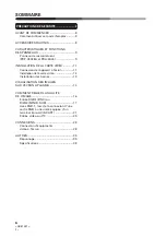
Page 5: ... unit to the monitor 11 Installing the video card 12 Installing the terminals 13 VIEWING IMAGES ON YOUR PLASMA DISPLAY 14 HOW TO ADJUST PICTURE QUALITY 16 RGB 1 BNC or RGB 2 MINI D SUB Input 16 With RGB 1 when inputting RGB output from a unit with a Euro AV SCART terminal 20 Video or Y C Input 24 CONNECTIONS 28 Connecting Video Devices to the Display 28 OTHERS 34 Troubleshooting 34 Specifications ...

Page 6: ...on de I appareil à I écran 11 Installation de la carte vidèo 12 Installation des bornes 13 VISUALISATION DES IMAGES SUR L ECRAN A PLASMA 14 COMMENT REGLER LA QUALITE DE L IMAGE 16 Entrée RGB 1 BNC ou RGB 2 MINI D SUB 17 Avec RGB 1 lors de la connexion d une sortie RGB à une unité équipée d un terminal Euro AV SCART 21 Entrée vidéo ou Y C 25 CONNEXIONS 28 Connexion d équipments vidéo à l écran 28 A...

Page 7: ...es Geräts am Monitor 11 Installieren der Videokarte 12 Installieren der Anschlüsse 13 BILDWIEDERGABE AUF IHREM PLASMA DISPLAY 14 EINSTELLEN DER BILDQUALITÄT 16 RGB 1 BNC oder RGB 2 MINI D SUB Eingang 17 Bei Empfang von RGB Signalen eines Geräts mit EURO A V Anschluß SCART über RGB 1 21 Video oder Y C Eingang 25 ANSCHLÜSSE 28 Anschluß von Videogeräten an das Display 28 VERSCHIEDENES 36 Fehlerbeseit...

Page 8: ...s familiariser avec les éléments les boutons et les commandes de cet appareil avec l écran à plasma et avec la télécommande reportez vous à la section CARACTERISTIQUES ET FONCTIONS DES PANNEAUX à la page 9 et à la section correspondante dans le mode d emploi du PDP V402EA Verwendung dieser Anleitung Die in dieser Anleitung enthaltenen Hinweise sind in einer Reihenfolge angeordnet die der logischen...

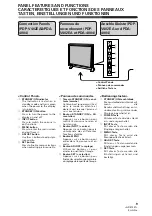
Page 9: ...r sur ce bouton pour entrer dans l écran menu et en sortir 5 Bouton ADJUST réglage Utiliser les boutons pour ajuster la qualité de l image 6 Bouton SET sélection Appuyer sur ce bouton pour finaliserlessélectionsdemenulors duréglagedelaqualitédel image PANEL FEATURES AND FUNCTIONS CARACTERISTIQUES ET FONCTIONS DES PANNEAUX TASTEN EINSTELLUNGEN UND FUNKTIONEN Anschlußleiste PDP V402EA und PDA 4004 B...

Page 10: ...le mode SYNC Normalement celui ci est réglé sur OFF arrêt Bornes d entrée RGB 1 0 Commutateur d impédance d entrée du signal de synchronisation 75 Ω 2 2 kΩ Borne d entrée du signal de synchronisation vertical 75 Ω 2 2 kΩ commutable avec le commutateur d impédance d entrée du signal de synchronisation Borne d entrée du signal de synchronisation horizontal ou composite 75Ω 2 2kΩ commut able avec l i...

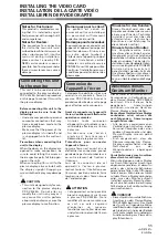
Page 11: ...oit car cela risquerait d entraîner un mauvais fonctionnement et ou de causer un dysfonctionnement de l écran à plasma Remarques pour le client Ce produit est vendu en assumant qu il sera installé par un personnel suffisamment expérimenté et qualifié Remarquepourlerevendeur La procédure pour connecter cet appareil à l appareil principal est décrite ci dessous Si une vis ou un autre objet tombait à...

Page 12: ...le circuit Pendant l installation veillez à ne pas créer d électricité statique et ne posez pas la carte vidéo sur des objets qui se chargent facilement d électricité statique Installezlacartevidéoetlepanneau de bornes en même temps Si vous n installez que l un de ces deux élémentsousil und euxestinstallé incorrectement le système ne se mettra pas sous tension Si cela se produit le signe d avertis...

Page 13: ... und sichern Sie danach die Klemmenleiste mit den im obigen Schritt 1 entfernten Schrauben 5 Bringen Sie das mitgelieferte Etikett 1 Loosen the screw in the door at the rear of the plasma display The screw is constructed so that it cannot be separated from the cover 2 Open the door 3 Install the video card to the four bosses so that the connectors are at the bottom Make sure that the four bosses r...

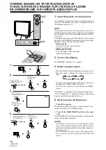
Page 14: ...he signal being input cannot be processed on this set 4 After use turn off the power 1 Turn off the power The standby indicator flashes in red for about 4 sec onds then remains lit standby state 2 Turn off the MAIN POWER switch on the main unit The STANDBY ON indicator will dim and the power to the unit will be turned off NOTES The buttons on the main unit and remote control unit and the external ...

Page 15: ...émoin en attente rouge continue à clignoter Ne pas afficher la même image images immobiles etc pendant une durée prolongée étant donné que l image peut alors rester collée à l écran VIDEO Y C RGB 2 RGB 1 VIDEO Y C RGB 2 RGB 1 1 Schalten Sie den Hauptschalter ein Die Bereitschafts Leuchtdiode blinkt etwa 4 Sekunden lang rot Dann wechselt das Gerät in den Bereitschaftszustand und die Bereitschafts L...

Page 16: ...nal input NOTE HOR POS may need to be adjusted in some cases if CLK FRQ has been ad justed CLK PHS When some letters in the picture flicker and the color becomes dis torted use this function Adjust it to minimize the flicker and the color dis tortion This function is to adjust the phase of the internal clock signal which is adjusted with the CLK FRQ function HOR POS Adjust the horizontal position ...

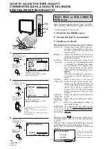
Page 17: ...ici Si YES a été sélectionné SET INIT sera affiché PICTURE PARAMETER SET EXIT INITIALIZE YES NO RGB 1 BNC oder RGB 2 MINI D SUB Eingang Für jeden Eingang sollte die Bildqualität eingestellt wer den für RGB 1 BNC RGB 2 D SUB Video und Y C Die verschiedenen Quellen finden Sie auf Seite 39 dieser Bedienungsanleitung 1 Wechseln Sie zur MENU Oberfläche 2 Wählen Sie die Funktion die Sie einstellen möcht...

Page 18: ...ave completed the set ting return to the normal screen NOTE When the interlaced signals such as NTSC PAL etc are input from the RGB input terminal adjust the HOR POS and VER POS horizontal and vertical positions so that the image becomes positioned in the center of the screen The picture may not be reproduced properly if the positions are altered extremely from the original ones 1 2 HOW TO ADJUST ...

Page 19: ...eren Funktionen einzustellen 5 Wenn Sie die Bildeinstellung abgeschlossen haben kehren Sie zur normalen Oberfläche zurück Anmerkung Wenn die Eingangssignale wie z B NTSC PAL usw über den RGB Eingang eingeleitet werden müssen HOR POS und VER POS waagerechte und senkrechte Position so eingestellt werden daß das Bild in der Bildschirmmitte positioniert ist Werden die Positionen im Vergleich zur Origi...

Page 20: ...PICTURE PARAMETER CONTRAST BRIGHT CLK FRQ CLK PHS HOR POS VER POS INIT SCART RGB SET SEL MENU EXIT 1 0 5 0 8 OFF Remote control Commande à distance Fernbedienung Main unit Unité principale Hauptgerät Remote control Commande à distance Fernbedienung Main unit Unité principale Hauptgerät Remote control Commande à distance Fernbedienung Main unit Unité principale Hauptgerät 1 Switch to the MENU scree...

Page 21: ...e la connexion d une sortie RGB à une unité équipée d un terminal Euro AV SCART 1 Passez à l écran MENU 2 Faites le défiler jusqu à SCART RGB 3 Appuyez sur le bouton de sélection SET Bei Empfang von RGB Signalen eines Geräts mit EURO A V Anschluß SCART über RGB 1 1 Display MENU aufrufen 2 SCART RGB wählen 3 Eingabetaste SET drücken ...

Page 22: ...SCART RGB to OFF Before you perform the above settings always first turn OFF the power to the unit connected to RGB 1 If you perform the above settings with the power to the unit connected to RGB 1 remaining ON in some cases there may be nothing on the screen or remote control operation will be ineffective If this occurs turn OFF both the main unit but ton and the power to the unit connected to RG...

Page 23: ...ance ne réponde pas Si tel était le cas appuyez sur le bouton de l unité principale et mettez l unité connectée à RGB 1 HORS tension et recommencez les réglages 4 Einstellung SCART RGB ON wählen 5 Eingabetaste SET drücken 6 Nach Beendigung der Eingabe schaltet der Monitor auf das normale Display Anmerkung Bei Empfang von RGB Signalen eines Geräts mit EURO A V Anschluß SCART über RGB 1 muß SCART RG...

Page 24: ...ntly selected item will be displayed in purple 2 Choose the item to be adjusted HOW TO ADJUST PICTURE QUALITY COMMENT REGLER LA QUALITE DE L IMAGE EINSTELLEN DER BILDQUALITÄT PICTURE PARAMETER CONTRAST BRIGHT COLOR SHARPNESS INIT SET SEL MENU EXIT PICTURE PARAMETER CONTRAST BRIGHT COLOR TINT SHARPNESS INIT SET SEL MENU EXIT PICTURE PARAMETER CONTRAST BRIGHT COLOR SHARPNESS INIT SET SEL MENU EXIT N...

Page 25: ... pourpre 2 Sélectionner l article à régler HOW TO ADJUST PICTURE QUALITY COMMENT REGLER LA QUALITE DE L IMAGE EINSTELLEN DER BILDQUALITÄT Video oder Y C Eingang 1 Wechseln Sie zur MENU Oberfläche Die gewählte Funktion wird purpurfarbig wiedergegeben 2 Wählen Sie die Funktion die eingestellt werden soll ...

Page 26: ...the picture as de sired Set it to a little lower position than that you want to obtain natural pictures TINT Adjusts the tint of the picture so that the face color looks natural Possible to adjust when the NTSC sig nal is inputted SHARPNESS Normally set to their center values But if you want images to be displayed in softer tones adjust it to the left from the center position INIT Returns the abov...

Page 27: ... Règle les nuances de l image de manière à ce que les visages prennent une coloration naturelle Possibilité de règlage lorsque le sig nal NTSC est introduit SHARPNESS Les définitions sont normalement réglées sur leur valeur standard Mais si vous souhaitez que les images affichées le soient dans des tonalités plus douces il suffit de régler à gauche par rapport à la position centrale INIT Ramène le...

Page 28: ...cope à cassette ou tuner TV 1 BNC 2 Câble avec bornes BNC disponible localement 3 BNC 4 V OUT BNC 5 Magnétoscope à cassette tuner TV ou analogues NOTE Si le terminal de sortie vidéo com posite du magnétoscope à cassette ou analogue à raccorder est un ter minal à broche RCA utiliser une prise d adaptation RCA BNC disponible localement CONNECTIONS CONNEXIONS ANSCHLÜSSE Anschluß von Videogeräten an d...

Page 29: ...nal or the like 2 En cas de dispositif avec sortie de séparation Y C 1 Câble avec bornes BNC disponible localement 2 BNC 3 C 4 Y 5 Magnétoscope à cassette à us age professionnel ou analogue 6 Câble pour conversion borne S borne BNC disponible localement 7 Borne S 8 Magnétoscope à cassette avec borne S ou analogue CONNECTIONS CONNEXIONS ANSCHLÜSSE 2 Geräte mit einem Y C getrennten Ausgang 1 Kabel m...

Page 30: ...Magnétoscope à cassette ou décodeur RGB à usage professionnel NOTES Si vous utilisez votre écran à plasma de cette façon ne raccorder aucun dispositif à sa borne VD ou HD Dans le cas contraire les images peuvent ne pas être reproduites correctement Lors de l entrée d un signal en RGB 1 il faut toujours effectuer le réglage indiqué à la page 17 dans le menu RGB 1 CONNECTIONS CONNEXIONS ANSCHLÜSSE 3...

Page 31: ...us utilisez votre écran à plas ma de cette façon ne pas connect er de dispositif à sa borne VD Dans le cas contraire les images peuvent ne pas être reproduites correctement Certains modèles Macintosh peu vent sortir à la fois G ON SYNC et SYNC composite En pareil cas l écran devient verdâtre si SYNC composite est sorti Pour ces modèles raccorder le G on SYNC de l étape 3 Lors de l entrée d un sign...

Page 32: ...odeur RGB pour usage professionnel ou analogue 0 Câble pour conversion BNC MINI Dsub 15 disponible localement NOTES Si vous connectez un ordinateur personnel comme celui illustré ci dessus il peut être nécessaire de disposer d un adaptateur en fonction du type d ordinateur Pour tous détails consulter le constructeur ou le revendeur d ordinateurs personnels Lors de l entrée d un signal en RGB 1 il ...

Page 33: ...entrée du signal de synchronisation composite ou horizontale 2 B BNC 3 G BNC 4 R BNC 5 SCART connecteur 6 Euro AV SCART câble de conversion BNC produit disponible sur le marché 7 unité équipée d un terminal Euro AV SCART 8 Réglez sur 75 Ω NOTE Lors de ce type de connexion effectuez toujours les réglages décrits en page 21 1 Den Videostecker BNC des Kabels am Eingang für das Horizontal bzw Komposit...

Page 34: ...DBY indi cator blinks and the power does not turn on The computer image from RGB 1 is not displayed There are no colors When the STANDBY indicator blinks successively twice The video card connector is not in serted firmly When the STANDBY indicator blinks successively three times The terminal panel is not inserted firmly The SCART RGB is set to ON The wire connector used to the connect video card ...

Page 35: ...ppareil ne se met pas sous tension L image de l ordinateur fournie sur RGB 1 n est pas affichée Il n y a pas de couleurs Si le témoin STANDBY clignote successivement deux fois Le connecteur de la carte vidéo n est pas inséré à fond Si le témoin STANDBY clignote successivement trois fois Le panneau de bornes n est pas inséré à fond Le SCART RGB est sur la position marche Le connecteur par câble uti...

Page 36: ...de blinkt und das Gerät läßt sich nicht einschalten Der an RGB 1 a n g e s c h l o s s e n e Computer wird nicht angezeigt Es werden keine Farben angezeigt Wenn die STANDBY Leuchtdiode zweimal aufeinanderfolgend blinkt Der Stecker der Videokarte ist nicht richtig eingesteckt Wenn die STANDBY Leuchdiode dreimal aufeinanderfolgend blinkt Die Klemmenleiste ist nicht richtig eingesteckt SCART RGB ist ...

Page 37: ...essure range of operation environment 0 8 1 1 atmospheres External dimensions 1Video card 156 w x 153 h x 32 7 d mm 2Terminal panel 92 w x 30 h x 29 4 d mm Weight 1Video card 0 32 kg 2Terminal panel 0 056 kg Accessories Terminal name label 1 Screw tap tight 3 x 8 2 Operating Instructions 1 Specifications OTHERS NOTE Specifications and design are subject to possible modifications without notice due...

Page 38: ...rvice 0 8 1 1 atmosphère Dimensions externes 1Carte vidÈo 156 l x 153 h x 32 7 p mm 2Panneau de bornes 92 l x 30 h x 29 4 p mm Poids 1Carte vidÈo 0 32 kg 2Panneau de bornes 0 056 kg Accessoires Etiquettes nominatives des bornes 1 Vis taraudage serré 3 x 8 2 Mode d emploi 1 Spécifications NOTE Ces spécifications et ce modèle peuvent être modifiés sans préavis dans un souci d amélioration Publicatio...

Page 39: ...ebungsdruckbereich 0 8 1 1atm Abmessungen 1Videokarte 156 B x 153 H x 32 7 T mm 2Anschlussplatine 92 B x 30 H x 29 4 T mm Gewicht 1Videokarte 0 32 kg 2Anschlussplatine 0 056 kg Zubehör Anschlussetikett 1 Schraube Blechschraube 3 x 8 2 Bedienungsanleitung 1 Technische Daten Anmerkung Wir behalten uns vor Design und Spezifikationen ohne Vorankündigung zu ändern Veröffentlicht von Pioneer Corporation...

Page 40: ...e le Precauzioni di sicurezza e le Istruzioni per l uso per apprendere l uso corretto del monitor Conservare il manuale in un luogo sicuro ed utilizzarlo come riferimento in futuro Note sull installazione Questo prodotto viene messo in vendita assumendone l installazione da parte di personale specializzato Affidarne l installazione sempre a personale competente o al negozio di acquisto PIONEER non...

Page 41: ...oet worden Bewaar deze handleiding op een veilige plek Hij zal u ook in de toekomst nog van pas komen Opmerkingenoverinstallatiewerk Dit product wordt op de markt gebracht ervan uitgaande dat het geïnstalleerd zal worden door bevoegd personeel met voldoende vaardigheden en competentie ter zake U dient het product te allen tijde te laten installeren en gebruiksklaar maken door een installatie speci...

Page 42: ...a forma de accionar debidamente el Plasma Display Guarde el manual en un lugar seguro En e futuro le resultará útil Notas sobre los trabajos de instalación Este producto se comercializa asumiendo que va a ser instalado por personal técnico cualificado que tenga la suficiente preparación y competencia Pida a un especialista en instalación o a su distribuidor que le haga la instalación y el ajuste d...

Page 43: ...llegamento di quest unità al monitor 49 Installazione della scheda video 50 Installazione dei contatti 51 ISTRUZIONI PER L USO 52 REGOLAZIONE DELLA QUALITA D IMMAGINE 54 Ingresso RGB 1 BNC o RGB 2 MINI D SUB 54 Con RGB 1 per l ingresso di un segnale in uscita RGB da un unità con un terminale Euro AV SCART 58 Ingresso video o Y C 62 COLLEGAMENTI 66 Collegamento di apparecchi video 66 VARIE 72 Ricer...

Page 44: ...n van dit toestel op de monitor 49 Installeren van de videokaart 50 Installeren van de aansluitingen 51 BEELDEN WEERGEVEN OP UW PLASMA DISPLAY 52 HET AFSTELLEN VAN DE BEELDKWALITEIT 54 RGB 1 BNC of RGB 2 MINI D SUB invoer 55 Met RGB 1 wanneer u een RGB signaal invoert van een toestel met een SCART aansluiting 59 Video of Y C invoer 63 AANSLUITINGEN 66 Aansluiting van videotoestellen met de display...

Page 45: ...49 Conexión de estaunidad al monitor 49 Instalaciòn de la tarjeta de vídeo 50 Instalaciòn de los terminales 51 VISIÓN DE IMÁGENES EN SU PLASMA DISPLAY 52 AJUSTE DE LA CALIDAD DE LA IMAGEN 54 Entrada RGB 1 BCN o RGB 2 MINI D SUB 55 Con RGB 1 cuando se reciba una señal RGB de una unidad con un terminal AV Euro SCART 59 Entrada de vídeo o Y C 63 CONEXIONES 66 Conexión de aparatos vídeo al Display 66 ...

Page 46: ...toetsen en de bedieningsorganen van dit toestel van de plasmadisplay en van de afstandsbediening beter te leren kennen raden we u aan eerst het hoofdstuk BEDIENINGSPANEEL EIGENSCHAPPEN EN FUNCTIES op bladzijde 47 door te nemen en het corresponderende hoofdstuk in de handleiding van de PDP V402EA Cómo utilizar este manual Este manual ha sido preparado para explicar las operaciones que deben realiza...

Page 47: ...Indrukken om het menuscherm te activeren en te deactiveren 5 ADJUST toets Gebruik de toetsen om de beeldkwaliteit bij te regelen 6 SET toets Indrukken om de menuselecties tijdens het afstellen van de bee ldkwaliteit te bevestigen COMANDI INGRESSI USCITE BEDIENINGSPANEEL EIGENSCHAPPEN EN FUNCTIES CARACTERÍSTICAS Y FUNCIONES DE LOS PANELES Cuadro de mandos y panel trasero PDP V402EA y PDA 4004 Cuadr...

Page 48: ...oerpoort voor horizontale of samengestelde synchroni satiesignalen 75 Ω 2 2 kΩ verwisselbaar met de schake laar voor het synchronisaties ignaal van de invoerimpedan tie Invoerpoort voor blauwe sig nalen 75 Ω Invoerpoort voor groene of groene en synchronisatiesig nalen ON SYNC 75 Ω Invoerpoort voor rode sig nalen 75 Ω Y C invoerpoorten Invoerpoort voor kleursig nalen 75 Ω Invoerpoort voor luminesce...

Page 49: ...roleer of het plasmadisplay uit staat en of de stekker daarvan uit het stopcontact gehaald is Voorzorgen bij het aansluiten van dit toestel op het display Wanneer de klepjes van het display geopend zijn om de aansluitingen tot stand te brengen moet u er op letten dat u de schroeven en eventuele andere onderdelen niet in de openingen in de beide toestellen laat vallen Wanneer u dit toestel aansluit...

Page 50: ... Onderwerp de videokaart nooit aan statische elektriciteit Statische elektriciteit kan het circuit vernietigen Let tijdens het installeren op dat u geen statische elektriciteit opwekt en dat u de videokaart niet boven op voorwerpen plaatst die makkelijk elektrisch worden geladen Installeer de videokaart en het aansluitpaneel tegelijkertijd Als u slechts één van beide installeert of als één van bei...

Page 51: ...tilizando los tornillos retirados en el paso 1 anterior 5 Coloque la etiqueta suministrada INSTALLAZIONE DELLA SCHEDA VIDEO INSTALLEREN VAN DE VIDEOKAART INSTALACIÓN DE LA TARJETA DE VÍDEO 1 Allentare la vite del portello nella parte posteriore dello schermo al plasma La vite è fatta in modo da non staccarsi dal portello 2 Aprire il portello 3 Installare la scheda video sui quattro risalti con i c...

Page 52: ... pulsante INGRESSO del quadro di comando del monitor fino ad ottenere l ingresso voluto nella seguente sequenza Per selezionare l ingresso con il telecomando premere il pulsante INPUT SELECT La selezione non si può effettuare con schermata MENU visualizzata Con RGB 1 oppure RGB 2 selezionato se non viene inviato nessun segnale in entrata viene visualizzato il messaggio NO SYNC Se il segnale inviat...

Page 53: ...eelden niet gedurende een lange tijd weer om te vermijden dat het beeld op het scherm blijft nalichten d w z dat het zichtbaar blijft nadat het signaal verdwenen is VIDEO Y C RGB 2 RGB 1 1 Aplique la energía al aparato princi pal El indicador de espera parpadeará en rojo durante aproximadamente 4 segundos Seguidamente la pantalla entra en estado de espera y el indicador permanece encendido NOTA Lo...

Page 54: ...rticale dell immagine INIT Riporta le suddette registrazioni al valore medio di default 1 SCART RGB Quest operazione seleziona il modo segnale di sincronizzazione Lasciarlo sempre su OFF tranne che nel caso di ingresso RGB in un unità con terminale Euro AV 1 Se si seleziona INIT appare la schermata di destra Selezionare YES oppure NO con i pulsanti 2 oppure 3 Selezionando YES e quindi premendo il ...

Page 55: ...e staan 32 to 32 128 to 127 32 to 32 32 to 32 Wanneer NO werd gese lecteerd zal hier de melding SET EXIT verschijnen Wanneer YES werd gese lecteerd zal hier de melding SET INIT verschijnen REGOLAZIONE DELLA QUALITA D IMMAGINE HET AFSTELLEN VAN DE BEELDKWALITEIT AJUSTE DE LA CALIDAD DE LA IMAGEN Entrada RGB 1 BNC o RGB 2 MINI D SUB Ajuste la calidad de la imagen para cada entrada RGB 1 BNC RGB 2 MI...

Page 56: ...l operazione 2 premere il pulsante SET Per regolare altri parametri ripetere le operazioni 2 a 4 5 Al termine di tutte le regolazioni ritornare alla schermata normale NOTA Se al terminale di ingresso RGB si applicano segnali interlacciati ad es NTSC PAL ecc regolare la posizione orizzontale e verticale HOR POS e VER POS in modo da posizionare l immagine al centro dello schermo L immagine potrà non...

Page 57: ...producida debidamente si las posiciones se modifican mucho con respecto a las originales 4 Ajuste la calidad de la imagen con respecto al elemento seleccionado 1 En caso de CONTRAST y BRIGHT 2 En caso de CLK FRQ CLK PHS HOR POS y VER POS Para volver a la pantalla de dos operaciones pulse el botón SET Repita las operaciones 2 a 4 para ajustar los otros elementos 5 Cuando haya terminado el ajuste vu...

Page 58: ...T BRIGHT CLK FRQ CLK PHS HOR POS VER POS INIT SCART RGB SET SEL MENU EXIT 1 0 5 0 8 OFF PICTURE PARAMETER CONTRAST BRIGHT CLK FRQ CLK PHS HOR POS VER POS INIT SCART RGB SET SEL MENU EXIT 1 0 5 0 8 OFF Telecomando Afstandsbediening Mando a distancia Monitor Hoofdtoestel Aparato principal Telecomando Afstandsbediening Mando a distancia Monitor Hoofdtoestel Aparato principal Telecomando Afstandsbedie...

Page 59: ... RGB 1 wanneer u een RGB signaal invoert van een toestel met een SCART aansluiting 1 Ga naar het MENU scherm 2 Scroll naar SCART RGB 3 Druk op de insteltoets SET Con RGB 1 cuando se reciba una señal RGB de una unidad con un terminal AV Euro SCART 1 Conmute a la pantalla MENU 2 Avance hasta SCART RGB 3 Pulse el botón de ajuste SET ...

Page 60: ...l segnale in uscita RGB girare sempre SCART RGB su OFF Prima di effettuare le impostazioni di cui sopra togliere innanzitutto l alimentazione che arriva all unità collegata ad RGB 1 Se si eseguono le impostazioni suddette con l alimentazione che arriva all unità collegata ad RGB 1 inserita in certi casi potrebbe non apparire nulla sullo schermo oppure l azionamento del telecomando potrebbe risulta...

Page 61: ...F y apague el suministro de corriente a la unidad conectada en RGB 1 después reinicie el sistema 4 Kies SCART RGB ON 5 Druk op de insteltoets SET 6 Keer terug naar het normale scherm zodra u klaar bent met de instelling Opmerking Wanneer de functie is ingesteld op RGB 1 dient u SCART RGB op ON te zetten voor het invoeren van een RGB signaal van een toestel met een SCART aansluiting Wanneer u terwi...

Page 62: ...selezione viene visualizzata in color viola 2 Selezionare il parametro da regolare PICTURE PARAMETER CONTRAST BRIGHT COLOR TINT SHARPNESS INIT SET SEL MENU EXIT ADJUST MENU MENU PICTURE PARAMETER CONTRAST BRIGHT COLOR SHARPNESS INIT SET SEL MENU EXIT PICTURE PARAMETER CONTRAST BRIGHT COLOR TINT SHARPNESS INIT SET SEL MENU EXIT PICTURE PARAMETER CONTRAST BRIGHT COLOR SHARPNESS INIT SET SEL MENU EXI...

Page 63: ...er weergegeven 2 Kies het item dat aangepast moet worden Entrada de vídeo o Y C 1 Conmute a la pantalla de MENÚ El elemento seleccionado aparecerá en color púrpura 2 Escoja el elemento a ajustar REGOLAZIONE DELLA QUALITA D IMMAGINE HET AFSTELLEN VAN DE BEELDKWALITEIT AJUSTE DE LA CALIDAD DE LA IMAGEN ...

Page 64: ...ciare la regolazione del fuoco al centro Se si vogliono però immagini più morbide spostarlo a sinistra INIT Riporta le suddette registrazioni al valore medio di default 1 Se si seleziona INIT appare la schermata di destra Selezionare YES oppure NO con i pulsanti 2 oppure 3 Selezionando YES e quindi premendo il pulsante SET si riportano al valore di default tutti i parametri di qualità dell imagine...

Page 65: ...mogelijk heid 1 Bij alle andere instelmogelijkheden dan TINT 2 Bij TINT Om terug te keren naar het scherm van stap 2 drukt U op de SET toets Herhaal de stappen 2 tot en met 4 om de andere in stelmogelijkheden af te regelen 5 Wanneer alles ingesteld is moet U naar het gewone scherm teruggaan 3 Ultime su elección Ajuste cada elemento como sigue CONTRAST Ajusta el contraste de la imagen de acuerdo co...

Page 66: ...n magnetoscopio o un sintonizador TV 1 BNC 2 Cable con terminales BNC disponibles en el mercado local 3 BNC 4 V OUT 5 Magnetoscopio sintonizador TV o similar NOTA Si el terminal de salida de vídeo compuesto del magnetoscopio o aparato similar a conectar es un terminal de patillas RCA utilizar un enchufe convertidor RCA BNC disponible en su mercado local Collegamento di apparecchi video 1 Sorgenti ...

Page 67: ...signalen met een S poort 2 Aparato del que sale separación Y C con un terminal S COLLEGAMENTI AANSLUITINGEN CONEXIONES 2 En caso de un aparato con salida de separación Y C 1 Cable con terminales BNC disponibles en el mercado local 2 BNC 3 C 4 Y 5 Magnetoscopio para uso comercial o similar 6 Cable convertidor de terminal S a terminal BNC disponible en el mercado local 7 Terminal S 8 Magnetoscopio c...

Page 68: ...rada RGB 2 active G en modo sincronizado Normalmente está desactivado 2 BNC 3 B 4 G 5 R 6 Cable con terminales BNC disponibles en el mercado local 7 G en SYNC 8 Magnetoscopio o descodificador RGB para uso comercial NOTAS Si utiliza su Plasma Display de este modo no conecte ningún aparato a su terminal VD o HD De lo contrario es posible que las imágenes no se reproduzcan debidamente Cuando se recib...

Page 69: ...2 kΩ 2 H V SYNC 3 B 4 G 5 R 6 Cable con terminales BNC dis ponibles en el mercado local 7 H V 8 VCR o descodificador RGB para uso comercial o similar NOTAS Si utiliza su Plasma Display de este modo no conecte ningún aparato a su terminal VD De lo contrario es posible que las imá genes no se reproduzcan debida mente Algunos modelos Macintosh pueden tener una salida tanto de G ON SYNC como de SYNC c...

Page 70: ...r el conmuta dor a 2 2 kΩ 2 Cable con terminales BNC disponible en el mercado local 3 BNC 4 VD 5 HD 6 B 7 G 8 R 9 1 Magnetoscopio o descodificador RGB para uso comercial o similar 0 Cable convertidor BNC MINI Dsub 15 disponible en el mercado local NOTAS Cuando conecte un ordenador personal como se indica arriba es posible que necesite un adaptador según el tipo de ordenador Para más detalles consu...

Page 71: ...l SCART BNC in de handel verkrijgbaar prod uct 7 Toestel met een SCART aansluiting 8 Ingesteld op 75 Ω Opmerking Wanneer u een signaal invoert van een toestel met een SCART aansluiting dient u altijd de instelling uit te voeren zoals beschreven op bladzijde 59 1 Conecte la patilla BNC de vídeo del cable al terminal de Entrada de la Señal Sinc Horizontal o Compuesta 2 B BNC 3 G BNC 4 R BNC 5 SCART ...

Page 72: ...L indicatoreSTANDBY lampeggia e l unità non si accende L immagine dal terminale RGB 1 per computer non viene visualizzata Colore assente Quando l indicatore STANDBY lampeggia due volte consecutive La scheda video non è bene inserita Quando l indicatore STANDBY lampeggia tre volte consecutive Il pannello terminali non è bene inserito SCART RGB si trova su ON Il connettore usato per la scheda video ...

Page 73: ...om kan niet worden ingeschakeld Het computerbeeld dat via RGB 1 binnenkomt wordt niet getoond Geen kleurweergave Wanneer de STANDBY indicator twee keer achter elkaar knippert De connector van de videokaart is niet goed aangesloten Wanneer de STANDBY indicator drie keer achter elkaar knippert Het aansluitingenpaneel is niet goed bevestigd De SCART RGB staat ON aan De connector tussen de videokaart ...

Page 74: ...y la alimentación no se conecta La imagen de c o m p u t a d o r a procedente de RGB 1 no se visualiza No hay colores Cuando el indicador STANDBY parpadee dos veces sucesivamente El conector de la tarjeta de vídeo no está conectado firmemente Cuando el indicador STANDBY parpadee sucesivamente tres veces El panel de terminales no está insertado firmemente SCART RGB está en ON El conector de cables ...

Page 75: ...e di funzionamento 0 40 C Pressione ammessa nell ambiente di funzionamento 0 8 1 1 atmosfere Dimensioni esterne 1Scheda video 156 l x 153 a x 32 7 p mm 2Basetta contatti 92 l x 30 a x 29 4 p mm Peso 1Scheda video 0 32 kg 2Basetta contatti 0 056 kg Accessori Targhetta denominazione contatti 1 Vite autofilettante 3 x 8 2 Istruzioni per l uso 1 Pubblicato da Pioneer Corporation Copyright 2000 Pioneer...

Page 76: ...n bedrijfsomgeving 0 C tot 40 C Toelaatbaar drukbereik van bedrijfsomgeving 0 8 1 1 bar Buitenafmetingen 1Videokaart 156 b x 153 h x 32 7 d mm 2Aansluitpaneel 92 b x 30 h x 29 4 d mm Gewicht 1Videokaart 0 32 kg 2Aansluitpaneel 0 056 kg Accessoires Naamlabel voor aansluiting 1 Schroef zelftappend 3 x 8 2 Gebruiksaanwijzing 1 Opmerking Deze specificaties en het design kunnen zonder voorafgaandelijke...

Page 77: ...cionamiento de 0 8 a 1 1 atmÛsferas Dimensiones externas en milÌmetros 1Tarjeta de vÌdeo 156 anchura x 153 altura x 32 7 profundidad 2Panel terminal 92 anchura x 30 altura x 29 4 profundidad Peso 1Tarjeta de vÌdeo 0 32 Kg 2Panel terminal 0 056 Kg Accesorios Etiqueta de nombre del terminal 1 Tornillos de apriete 3 x 8 2 Manual de instrucciones 1 NOTA Las especificaciones y el diseño están sujetos a...

Page 78: ......

Page 79: ......

Page 80: ...undary Road Braeside Victoria 3195 Australia TEL 61 39 586 6300 PIONEER ELECTRONICS ASIACENTRE PTE LTD 253 Alexandra Road 04 01 Singapore 159936 TEL 65 472 1111 PIONEER ELECTRONICS CHINA LTD Room 1704 06 17 F World Trade Centre 280 Gloucester Rd Causeway Bay H K TEL 852 2848 6488 PIONEER GULF FZE P O BOX 61226 Jebel Ali Dubai United Arab Emirates TEL 971 4 815756 Published by Pioneer Corporation C...

Reviews: