background image

1

GOLD 1-3 SK-GB -708

Right to make modifications without prior notice

:

::

:

Commissioning, operation,
and maintenance: GOLD 1-3

1.

INTRODUCTION ............................................................ 1

2.

ELECTRICAL CONNECTION ........................................ 4

3.

CONNECTION OF EXTERNAL FUNCTIONS ............... 5

4.

WIRING DIAGRAM POWER CARD .............................. 6

5.

WIRING DIAGRAM CONTROL CARD .......................... 7

6.

STARTING-UP ............................................................... 8

7.

ADJUSTMENTS ............................................................. 9

8.

FUNCTIONS ................................................................. 13

9.

ADJUSTMENT PROTOCOLE ...................................... 18

10. ALARM ......................................................................... 19

11. MAINTENANCE ............................................................ 21

TELEPHONE NUMBERS PM-LUFT ............................ 22

INDEX

1. INTRODUCTION

1.1 GENERAL

GOLD is a complete air handling unit, with built-in control
system, developed and manufactured by PM-LUFT AB.
The unit contains supply and exhaust air fans, rotary heat
exchanger Turbo, supply and exhaust air filters F85/EU7
and control system.

These instructions are for the commissioning, operation,
and maintenance of the unit. It is important that they are
read by all personnel involved before the unit is put into
service. Please see separate instructions for installation

WARNING!

Inspection hatches located on the pressure side behind
the fan must not be opened while the fan is operating. The
hatch can open suddenly and cause personal injury.

Summary of Contents for GOLD 1

Page 1: ...s a complete air handling unit with built in control system developed and manufactured by PM LUFT AB The unit contains supply and exhaust air fans rotary heat exchanger Turbo supply and exhaust air filters F85 EU7 and control system These instructions are for the commissioning operation and maintenance of the unit It is important that they are read by all personnel involved before the unit is put ...

Page 2: ...ansformer 12 VDC GOLZ 1 06 For supply to motion detector Set of Hinges GOLZ 1 a 07 Delivered unassembled Cannot be used with the GOLZ stand Size 1 2 3 Replacement Material Filter F85 EU7 1 pc GOLZ 1 a 01 Size 1 2 3 Air Handling System GOLD a b cc Type Size 1 2 2 3 3 Size 1 2 3 Display Language SWE ENG 01 SWE FIN 02 POL ENG 03 TJECK TY 04 FRA ENG 05 EST ENG 06 COMPLEMENTS Damper and motor GOSA 1 aa...

Page 3: ...ard Main safetyswitch Locking knobs fan Drive Motor Heat Exchanger Supply Air Filter Heat Exchanger Exhaust Air Filter Throttle Damper Exhaust Air Sensor Main Safety Breaker Clamp Belt Outdoor Air Sensor SUPPLY Supply Air Fan Drive Belt Heat Exchanger EXHAUST Electric Plug Size 2 Locking Knobs Fan Assembly Control Box with Controller Card Power Card EXTRACT OUTDOOR GOLD size 1 GOLD 2 and 3 Outdoor...

Page 4: ...nit or possible reheater Shall always be mounted after coil 2 5 Reheater 2 5 1 Electrical heater Power supply shall be carried out through working switch directly from distribution box Unit size 1 2 0 kW 2 phase 400 v earth 5 0 A Unit size 2 3 6 kW 2 phase 400 V earth 9 0 A Unit size 3 6 0 kW 3 phase 400 V earth 8 7 A Control signal to the built in thyristor is connected to the unit via a quick co...

Page 5: ...all the time 3 5 External set value displacement Connections 7 and 8 is input for 0 10 VDC for displacement of set value Upon regulation of supply exhaust air the set value for supply exhaust air temperature is displaced Upon regulation of ERS the difference between EA SA is displaced The function is activated in the display The influence is 5 C according to 8 4 3 6 Flow indication Supply Exhaust ...

Page 6: ... 5 6 7 1 2 3 4 5 6 7 SUPPLY AND CONTROL FROM CONTROL CARD OUTDOOR AIR SENSOR EXHAUST AIR FAN SUPPLY AND CONTROL HEAT EXCH MOTOR EXHAUST AIR SENSOR Black Brown Black Yell Green Blue Brown Yell Grey Blue Brown White Green Yellow White Brown Blue Brown Black Yell Green Blue Brown White Yellow Green 1 2 Black Yell Green Blue Brown White Yellow Green GOLD POWER GOLD PRESSURE FUSE 1 A folio 4 WIRING DIA...

Page 7: ... Brown Yellow Green Blue Brown Brown White 24 21 22 23 20 17 18 19 16 13 14 15 L1 27 28 2 x 230 V INPUT L2 N1 N2 Brown Yell G Blue Supply SA fan Black Blue Blue Brown Brown Yellow Green Blue Blue Brown Blue Brown White Brown Blue Yell Green Yell Green 1 7 6 5 4 3 2 4 3 2 1 2 1 4 3 GOLD CPU GOLD PROG GOLD CONTROL 11 12 9 10 7 8 5 6 3 4 1 2 Yell Green Yell Green GOLD CONTROL CARD DC OUTPUT FL TL DC ...

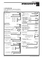
Page 8: ... operation type choosen STOP AUTOOPER or MANUALOPER In this case STOP is shown Normally the unit shall operate in AUTO OPER which is shown in the next sketch since the switching clock handles alteration from High to Low speed The second line shows which operating mode is current HIGH SPEED LOW SPEED or STOP If any other function is affecting the flow it flashes on the second line alternately with ...

Page 9: ...ers alter back to read off mode See also 9 Adjustment protocole HIGH SPEED 00 00 00 00 DAY 1 NO 1 RET PROG COOLING UNIT 0 DUCT CALIBR 0 SERV PERIOD 12 MONTHS RET PROG ANTI FR GUARD FUNC 0 RET PROG SUPP AIR FILTER FILTER STATUS NOW 01 ALARM LIMIT 10 RET PROG RET PROG 1 SVENSKA 2 ENGLISH RET PROG MAN STOP S CL PROG GOLD DAY 1 10 15 HIGH SPEED AUTO OPER ACTUAL TIME DAY 1 10 15 RET PROG GOLD DAY 1 10 ...

Page 10: ...en time In certain cases two variants can be necessary i e if high speed over a 24 hour joint is required First from required time to 23 59 then new variant from 0 00 to required time The unit will then operate at high speed during the programmed times 7 2 Switching clock First programme the right day and time Then programme desired times for High speed operation GOLD DAY 1 10 15 PV 02 2 OPER 0250...

Page 11: ...ture shall be below the exhaust air temperature below the break point in the diagram to the right The diagram is drawn for 3 C DIFF The BREAK POINT is the point in the diagram from where the steps starts It is defined from the exhaust air temperature In the diagram the breakpoint is 22 C 7 4 2 Other regulation types Change of regulation form to EXHAUST AIR REGULATION or SUPPLY AIR REGULATION is ca...

Page 12: ...nect the manometer or other pressure meter to the connections for and and measure both pressures NOTE With both nipples negative pressures are measured If the negative pressure on the exhaust air side is at least as high as on supply air the adjustment is ready If not remove the inspection door adjust the damper slightly put back the inspection door and measure the pressures Repeat until the negat...

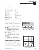
Page 13: ... regulation The temperature set value is increased if the outdoor air temperature drops below 10 C according to winter compensation curve or raises above 25 C according to summer compensation curve See diagram to the right SUMMER NIGHT COOL 0 OUTD AIR TEMP COMP 0 SET VALUE DISPL 0 RET PROG 8 2 Summer night cooling At summer night cooling 1 on the unit is operating on high speed with a supply air o...

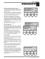
Page 14: ...ng on off At COOLING UNIT 1 on When need of cooling occurs a closure of free making contact is obtained connection box 17 18 This closure can be used to start an external cooling unit When the need of cooling stops the contact opens and a restart time of 10 minutes starts running This is to prevent too many start stops of the cooling unit A neutral zone of 2 C is programmed so that set value at co...

Page 15: ...value the contact opens and a restart time of 10 minutes begins to run The contact also opens when SA MIN goes below the set value upon Exhaust Air regulation 8 6 Duct calibration At DUCT CALIBR 1 on The unit is operating on a firm calibration flow and measures where in the flow diagram the unit is operating with care taken to connected duct system and with clean filters Duct calibration shall alw...

Page 16: ...or the user is at hand as the unit both is stopped and operates on filter test flow regardless to what flow is chosen Factory set value is 22 59 While External Stop is activated no filter tests are done The filter test can be done if the aggregate is running at low or high speed Low speed can be set to 0 l s i e shut off but still active The filter test cannot be done on a manually stopped aggrega...

Page 17: ...is no need of heating and the rotor does not operate After ca 3 5 hours the rotor is started during 1 minute on max for purging Recooling If the reheater has been operating the coil is cooled off on min flow during 3 minutes despite if Stop has been ordered The text RECOOLING flashes on the second line on the display Zero calibration Every time the fans are stopped the regulation controls that the...

Page 18: ...mmer night cooling 0 Outdoor air temp compensation 0 Set value displcement 0 Cooling unit on off Stepless 0 10V 0 Duct calibration carried out Service period months 12 Ext high speed low speed input switch off delay hours min 0 00 closure high speed low speed high speed Time for filter test 22 59 Anti freeze guard function 0 When having water coil Demands anti freeze guard sensor Alarm limit filte...

Page 19: ...ssor on the power card Check that the processors are placed correctly in the sockets Check that the cable between the cards is correctly connected Manual reset on display ALARM 11 CONTROL CARD BROKEN A alarm the unit has stopped ALARM 6 SUPP AIR TEMP SENSOR BROKEN ALARM 1 SUPP AIR MOTOR RELEASED ALARM 2 EXH AIR MOTOR RELEASED A alarm the unit has stopped The summary alarm from the supply air motor...

Page 20: ... The test is activated if the difference between supply air temperature and outdoor temperature is more than 10 C The exchanger runs at 100 for four minutes If the difference between Exhaust Air and Supply Air is greater than 8 C the alarm is activated Check the drive belt and the drive motor Manual reset on display The degree of soiling has overstepped the alarm limit four tests in a row The alar...

Page 21: ... fan brackets are attached with 2 locking knobs and the flexible web hose with 1 locking knob On Sizes 2 and 3 the fan assembly is attached with 2 locking knobs The flexible web hose is attached over the collar using a clamp belt with off centre lock All locking wheels must be loosened before disassembly Also the contacts the cables are loosenened before the fans are withdrawn The fans are vacuum ...

Page 22: ...2 300 REPRESENTS CZECHO Mlada Boleslav 0326 292 34 DENMARK Århus 86 17 00 11 FINLAND Helsingfors 90 879 70 70 GERMANY Berlin 030 495 01 61 GREECE Kallithea 01 930 59 64 THENETHERLANDS Almere Vaart03240 24092 ICELAND Reykjavik 91 175 60 NORWAY Oslo 22 50 98 80 POLAND Poznan 061 47 71 43 GREAT BRITAIN London 01440 71 46 99 HUNGARY Budapest 36 1 157 10 75 ...

Reviews: