background image

1

RMX

®

 2000 Installation & 

Configuration Guide

General Safety Precautions

Follow these rules to ensure general safety:

Keep the area around the Polycom RMX

®

 2000 unit clean and free 

of clutter and well ventilated.

Decide on a suitable location for the equipment rack that will hold 

the RMX, ensuring that it is near a grounded power outlet.

Ensure that the leveling jacks on the bottom of the rack are fully 

extended to the floor with the full weight of the rack resting on 

them. Always make sure the rack is stable before extending a 

component from the rack.

In a single rack installation, attach stabilizers to the rack. In 

multiple rack installations, the racks should be coupled together.

Use a regulating uninterruptable power supply (UPS) to protect the 

RMX from power surges and voltage spikes, and to keep it 

operating in the event of a power failure.

Allow the power supply units to cool before touching them.

Always keep the rack’s trays and board’s closed when not 

servicing, to maintain proper cooling.

Preparations

Obtain the following information from your network administrator:

IP addresses, Subnet Mask and Default Gateway IP address 

(optional) for the RMX control unit and RMX Shelf Management.

IP addresses for the RMX Signaling Host and Media cards.

Gatekeeper IP address.

SIP server IP address, if applicable.

Summary of Contents for RMX 2000

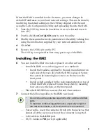
Page 1: ... In a single rack installation attach stabilizers to the rack In multiple rack installations the racks should be coupled together Use a regulating uninterruptable power supply UPS to protect the RMX from power surges and voltage spikes and to keep it operating in the event of a power failure Allow the power supply units to cool before touching them Always keep the rack s trays and board s closed w...

Page 2: ...essories kit contains the power cables and a USB Key 3 Remove the top cover lift the RMX 2000 from the package and place it on a flat surface Management Network Configuration on the USB Key The system is shipped with the following default IP addresses Control unit IP address 192 168 1 254 Shelf Management IP Address 192 168 1 252 Control unit subnet mask 255 255 255 0 Default Router IP Address 192...

Page 3: ...k or place it on a flat surface Install the RMX on a rack using one of two methods Install the brackets supplied by the rack manufacturer on each side of the rack on which the RMX is placed Secure the system by fastening four screws to the rack on the front panel Install a shelf supplied by the rack manufacturer on top of which the RMX is placed Secure the system by fastening four screws to the ra...

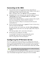
Page 4: ... are no System Errors the green RDY LED on the CNTL module on the RMX s front panel turns ON 10 Remove the USB key Product Registration and Activation Key Retrieval Before starting the initial configuration process register the RMX at the Polycom Resource Center website and download the product activation key file to the computer you will use for the configuration 1 Using a Web browser connect to ...

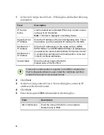
Page 5: ... Key click the Polycom Resource Center button to access the Service Support page of the Polycom website The system prompts with a System Reset dialog box 4 In the System Reset dialog box click No As no Default IP Network Service is defined the system automatically starts the Fast Configuration Wizard The Fast Configuration Wizard is displayed Configuring the IP Network Service The Fast Configurati...

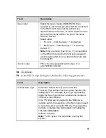
Page 6: ...Signaling host This is the address used by endpoints for dialing in to the MCU Media Card 1 IP Address Enter the IP address es of the media card s MPM MPM MPMx 1 and MPM MPM MPMx 2 if installed as provided by the network administrator Endpoints connect to conferences and transmit call media video voice and content via these addresses Media Card 2 IP Address Subnet Mask Enter the subnet mask of the...

Page 7: ...f the DNS servers Note The IP address fields are enabled only if Specify is selected Register Host Names Automatically to DNS Server Select this option to automatically register the MCU Signaling Host and Shelf Management with the DNS server Local Domain Name Enter the name of the domain where the MCU is installed Primary DNS Server IP Address The static IP addresses of the primary DNS server Fiel...

Page 8: ...es Alias The alias by which the RMX s Control Unit is identified within the network Up to five aliases can be defined for each RMX Note When a gatekeeper is specified at least one prefix or alias must be entered in the table Type Select the type that defines the format in which the card alias is sent to the gatekeeper H 323 ID alphanumeric ID E 164 0 9 URL ID URL style address Transport ID IP addr...

Page 9: ...cording to the protocol supported by the SIP Server UDP Select this option to use UDP for signaling TCP Select this option to use TCP for signaling TLS The Signaling Host listens on secured port 5061 only and all outgoing connections are established on secured connections Calls from SIP clients or servers to non secured ports are rejected The supported security protocols are TLS 1 0 SSL 2 0 and SS...

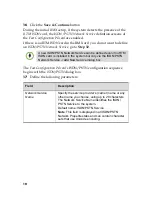
Page 10: ...s with the ISDN PSTN dialog box 17 Define the following parameters A new ISDN PSTN Network Service can be defined even if no RTM ISDN card is installed in the system but only via the ISDN PSTN Network Service Add New Service dialog box Field Description Network Service Name Specify the service provider s carrier name or any other name you choose using up to 20 characters The Network Service Name i...

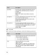
Page 11: ...pe E1 all other spans that you may later define must also be of type E1 Service Type PRI is the only supported service type It is automatically selected Field Description Default Num Type Select the Default Num Type from the list The Num Type defines how the system handles the dialing digits For example if you type eight dialing digits the Num Type defines whether this number is national or intern...

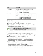
Page 12: ...e used Default None Dial out Prefix Enter the prefix that the PBX requires to dial out Leave this field blank if a dial out prefix is not required The field can contain be empty blank or a numeric value between 0 and 9999 Default Blank Field Description Framing Select the Framing format used by the carrier for the network interface from the list For T1 spans default is SFSF For E1 spans default is...

Page 13: ...nection indicates the MCU CLI number as seen by the participant 28 Click Save Continue After clicking Save Continue you cannot use the Back button to return to previous configuration dialog boxes The ISDN PSTN Network Service is created and confirmed 29 Click OK to continue the configuration Line Coding Select the PRI line coding method from the list For T1 spans default is B8ZS For E1 spans defau...

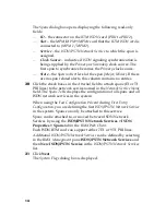
Page 14: ...pans E1 or T1 PRI lines to the network service named in the Network Service Name field The Spans Table displays the configuration of all spans and all ISDN network services in the system When using the Fast Configuration Wizard during First Entry Configuration you are defining the first ISDN PSTN Network Service in the system Spans can only be attached to this service Spans can be attached to or m...

Page 15: ... ID Length User The minimum number of digits that the user must enter when manually assigning a numeric ID to a conference Range 2 16 Default 4 Selecting 2 digits limits the number of simultaneous ongoing conferences to 99 Maximum Conference ID Length User The maximum number of digits that the user can enter when manually assigning a Numeric ID to a conference Range 2 16 Default 8 MCU Display Name...

Page 16: ...Username and Password are both POLYCOM The RMX Web Client opens An MCU State indicator displays a progress indicator showing the time remaining until the system start up is complete 39 Create a new User with Administrator permissions and delete the Default User POLYCOM For more information see User Definition on page 17 For system security reasons the system is not fully configured until this step...

Page 17: ...opens 3 In the User Name text box enter the name of the new user This is the login name used by the user when logging into the system 4 In the Password text box enter the new user s password This will be the user s password when logging into the system 5 In the Authorization Level list select the user type which determines the application display and functionality 6 Click OK To delete a user from ...

Page 18: ...004 The default conferencing entities are set to line rate of 384 Kbps Auto Layout Polycom Skin and have a default duration of one hour The default Entry Queue is also set to Ad Hoc conferencing which allows participants to start new conferences without prior definition by entering a Conference or Meeting Room ID other than those used for the default Meeting Rooms and that is not used by any on go...

Page 19: ... Entry Queue ID 1000 default Meeting Room IDs 1001 1002 1003 and 1004 H 323 Participants H 323 participants dial MCU Prefix in Gatekeeper Conference or Entry Queue ID Name For example if the MCU prefix in gatekeeper is 925 you can dial to the default Transit Entry Queue by entering 925 or 9251000 and be routed to Meeting Rooms by entering its ID i e 1001 1002 1003 or 1004 You can connect directly ...

Page 20: ...ference ID For example if the assigned dial in number is 4045555 the ISDN PSTN participant dials this number with the appropriate area code for example 678 and country code 001 Conference Control Using DTMF Codes Operation DTMF String Individual Help 0 Conference Help 00 Mute My Line 6 Unmute My Line 6 Increase Broadcast Volume 9 Decrease Broadcast Volume 9 Increase Listening Volume 76 Decrease Li...

Reviews: