background image

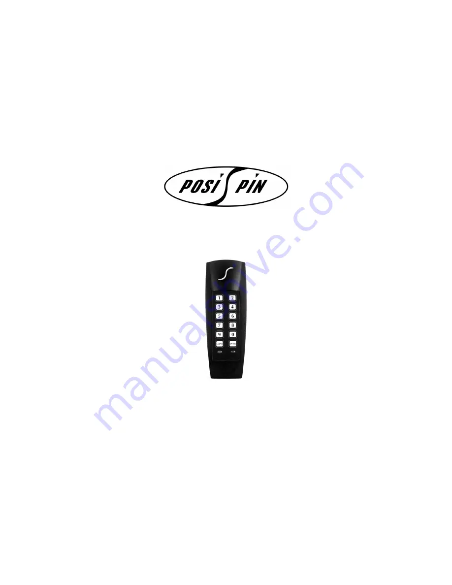
PIN and Proximity Reader

For Access Control Systems

(CR-R885-A)

Installation and Operating Instructions

Version 1.0

Summary of Contents for CR-R885-A

Page 1: ...PIN and Proximity Reader For Access Control Systems CR R885 A Installation and Operating Instructions Version 1 0...

Page 2: ......

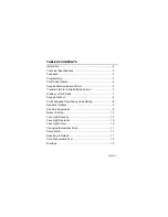
Page 3: ...imit for 4 bits Buffered Format 7 Display on Card Read 7 Keypad Lockout 8 26 bit Wiegand Card Family Code Setting 8 Reader s Interface 9 Check in Supervision 9 Buzzer Setting 10 Face Light Intensity 1...

Page 4: ...oid sites within 1 1m 3 5ft of computer monitors or CRTs Avoid sites near sources of broad spectrum EMI noise such as motors pumps generators DC to AC converters AC switching relays power supplies and...

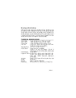
Page 5: ...Vdc with card 105mA Consumption Typical 812mW 12 5Vdc with card 1 31mW Frequency Exciter Field 125KHz Pulse Modulated receive low 12 500KHz Receive high 15 625KHz Operating Temp 35 C 31 F to 65 C 149...

Page 6: ...4 Installation and Operating Instructions Figure 1 Connection drawing...

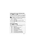
Page 7: ...mpleted in the control panel or controller connected to the PosiPin To program 1 Press and hold the CLEAR key for 4 seconds The reader emits a confirmation beep and the green LED illuminates 2 Enter t...

Page 8: ...abled For programming only 1 Reader only enabled A user must present a valid card to the reader for Access Granted 2 Keypad only enabled A user must enter a valid code on the keypad for Access Granted...

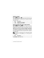
Page 9: ...bits buffered with parity DISPLAY ON CARD READ Section 004 004 004 004 Default 3 3 3 3 PosiPin s response to a card being presented to the reader can be adjusted according to the installation s requir...

Page 10: ...must be programmed in order for the keypad to recognize the user s PIN When a user enters a PIN on the keypad PosiPin will automatically add the family code programmed in section 006 to the beginning...

Page 11: ...t for Option 1 26 bit Wiegand or Option 2 37 bit Wiegand When no actions are performed on the PosiPin for a period of time it will communicate its status to the controller every 30 seconds by sending...

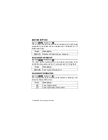
Page 12: ...Default 4 4 4 4 The Face Light s illumination can be adjusted according to the installation s requirements from 0 extinguished to 8 brightest FACE LIGHT OPERATION Section 103 103 103 103 Default 1 1...

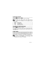
Page 13: ...Code is used to enter PosiPin s programming mode The Installer Code is six digits long where each digit can be any value from 0 to 9 PANIC ALARM A panic code can be generated and transmitted to the co...

Page 14: ...y CARD PRESENTATION TEST Present the card to the reader as shown in the figure below Place the card parallel to the PosiPin reader and move it toward the reader until the card code displays on the con...

Page 15: ...conjunction with products not manufactured by Seller Seller cannot guarantee the performance of the security system Seller obligation and liability under this warranty is expressly limited to repairin...

Page 16: ...Printed in Canada 04 2001 PPINEI 00...

Reviews: