background image

Instruction Bulletin - 01.4IB.67000

Power/Vac® Metal-Clad Switchgear

5kV & 15kV

20kA, 25kA, 31.5kA, 40kA, 50kA, & 63kA

1200A, 2000A, 3000A, 3500A, & 4000A FC

Powered by Safety

®

Summary of Contents for Power/Vac

Page 1: ...Instruction Bulletin 01 4IB 67000 Power Vac Metal Clad Switchgear 5kV 15kV 20kA 25kA 31 5kA 40kA 50kA 63kA 1200A 2000A 3000A 3500A 4000A FC Powered by Safety ...

Page 2: ...fety Power Vac Metal Clad Switchgear 5kV 15kV 01 4IB 67000 Contact Information Powell Electrical Systems Inc powellind com info powellind com Service Division 7232 Airport Blvd Houston Texas 77061 Tel 1 800 480 7273 ...

Page 3: ...ut the safety alert symbol is used to address practices not related to personal injury CAUTION NOTICE NOTICE is used to address practices not related to personal injury Qualified Person For the purposes of this manual a qualified person as stated in NFPA 70E is one who has skills and knowledge related to the construction and operation of the electrical equipment and installations and has received ...

Page 4: ...cription 5 A General 5 B Primary Compartment 5 C Secondary Compartment 9 D Breaker Removable Element 9 E Breaker Lift Truck 10 F Ratings 10 G Lighting Impulse Withstand BIL 10 H Circuit Breaker Racking Mechanism 10 I Remote Racking 11 J Primary Disconnect Devices 11 K Bus Compartment 12 L Current Transformer Compartment 12 M Primary Termination Space 12 N Voltage Transformers 13 O Current Limiting...

Page 5: ...Adding Units to Outdoor Equipment with a Protected Common Aisle 31 J Instructions For Making Bus Connections Across Shipping Split Sections 31 1 Introduction 31 2 Main Bus Connections Across the Shipping Split 31 3 Tie Bus Connections Across the Shipping Split 35 K Instructions for Bolting Stacks Together Across Shipping Split Sections 36 1 Introduction 36 L Connections 38 1 Main Bus Bars 38 2 Sli...

Page 6: ...dlocks 57 L Stationary Auxiliary Switch 57 M Breaker Position Switch 57 N Space Heaters 57 Ch 6 Maintenance 59 A General 59 B Overall Maintenance Procedures 59 1 Equipment 59 2 Bus Insulation 59 3 Racking Mechanisms 60 4 Primary Disconnect Device Contacts 60 5 Disconnecting Contacts 60 6 Control Contacts 60 7 Secondary Wiring 60 8 Mechanical Parts 60 9 Ventilation 60 10 Battery and Charging Equipm...

Page 7: ...r with Protected Aisle 28 Figure 14 Assembly of Outdoor Switchgear with Protected Aisle cont 29 Figure 15 Front Upper Compartment 32 Figure 16 View Looking Up Into Front Bottom Compartment of a 2 High 32 Figure 17 Taptite Location in Front Upper Compartment 32 Figure 18 View of Typical Front Lower Breaker Compartment 32 Figure 19 View of Typical Front Lower PT CPT Rollout Compartment 33 Figure 20 ...

Page 8: ...43 Figure 36 Cable Termination Joint 45 Figure 37 Rear View of Unit Showing Ground Fault Current Transformer 46 Figure 38 Bar Type Current Transformer Joint Insulation 46 Figure 39 Roof Bushing 48 Figure 40 Lift Truck 52 Figure 41 Left Side Racking Rail 56 Figure 42 Right Side Racking Rail 56 Figure 43 Stationary Auxiliary Switch Circuit Breaker Position Indicator 57 ...

Page 9: ...le D Bus Wrapping Components 40 Table E Insulation of Bus Bar 40 Table F Insulation of Single Bus Bar Connection Joint 41 Table G Insulation of Double Bus Bar Connection Joint 41 Table H Insulation of Tee Connection Joint 42 Table I Insulation of Dead End Bus Joint 42 Table J Cable Termination Joint 45 Table K Bar Type Current Transformer Joint Insulation 46 Table L Pothead Bushing or Terminator 4...

Page 10: ...Powered by Safety Power Vac Metal Clad Switchgear 5kV 15kV 01 4IB 67000 This page is intentionally left blank ...

Page 11: ... servicing maintenance or any act requiring the operator to make physical contact with the equipment the power source must be disconnected and the equipment grounded Failure to do so may result in death or serious injury NOTICE The information in this instruction bulletin is not intended to explain all details or variations of the Powell equipment nor to provide for every possible contingency or h...

Page 12: ...t replacement 4 Information for ordering renewal parts 5 Illustrations photographs and description of the switchgear The illustrations contained in this document may not represent the exact construction details of each particular type of metal clad switchgear The illustrations in this document are provided as general information to aid in showing component locations only All illustrations and phot...

Page 13: ...e measurement and test instruments intended for use on electrical systems 1000 V and below 6 Where the possibility of induced voltages or stored electrical energy exists ground the phase conductors or circuit parts before touching them Where it could be reasonably anticipated that the conductors or circuit parts being deenergized could contact other exposed energized conductors or circuit parts ap...

Page 14: ...condition 2 DO NOT WORK ON THE SWITCHGEAR WITH THE CONTROL CIRCUIT ENERGIZED 3 EXTREME CARE MUST BE EXERCISED TO KEEP ALL PERSONNEL TOOLS AND OTHER OBJECTS CLEAR OF MECHANISMS WHICH ARE TO BE OPERATED DISCHARGED OR RELEASED These circuit breakers utilize stored energy mechanisms These mechanism must be serviced only by skilled and knowledgeable personnel capable of releasing each spring load in a ...

Page 15: ...t improvement It is possible that improvements occurred between revisions to this document and therefore may not be described in these instructions If the equipment does not resemble the photographs and descriptions contained herein do not attempt to perform the actions Contact the Powell Service Division NOTICE Power Vac Metal Clad Switchgear equipped with vacuum circuit breakers is designed to c...

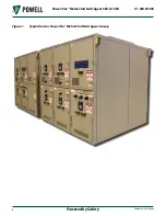
Page 16: ...Powered by Safety 6 Equipment Description Power Vac Metal Clad Switchgear 5kV 15kV 01 4IB 67000 Figure 1 Typical Indoor Power Vac Metal Clad Switchgear Lineup ...

Page 17: ...Powered by Safety 7 Equipment Description 01 4IB 67000 Figure 2 Typical Outdoor Power Vac Metal Clad Switchgear Lineup ...

Page 18: ...on Continuous Current Rating Amperes Short Circuit Rating kA Height inches Depth inches One High 1200 2000 3000 20 25 31 5 40 50 63 95 94 Two High 1200 2000 20 25 31 5 40 50 63 95 94 One High 3500 20 25 31 5 40 50 63 95 106 One High 4000 Force Cooled 20 25 31 5 40 50 63 106 106 Figure 3 Interior Metal Clad Switchgear Lower Compartment ...

Page 19: ...ipment where the circuit breaker is withdrawn The compartment is provided with a hinged panel upon which are mounted the necessary instruments control and protective devices The terminal blocks fuse blocks and some control devices are mounted inside the compartment on the side sheets and on the internal device panel A wiring space is provided across the top of the switchgear to run wires between v...

Page 20: ...level is 60kV for the 4 16kV class switchgear and 95kV for the 8 25kV and 13 8kV class switchgear The basic impulse level testing excludes control transformers starting reactors and autotransformers Note If required AC Field Dielectric Tests should be limited to 75 of Factory Dielectric Test values Direct current dielectric testing is not recommended If DC testing is required see Ch 4 Installation...

Page 21: ...connected and test positions from a remote location It is easily mounted to the breaker compartment front door and is designed for quick transfer between units The remote racking device is furnished in two operating voltage versions The 115VAC 50 60Hz model has a four foot electrical cord with standard three prong plug to fit a grounded receptacle or extension cord The 230VAC 50 60Hz model has a t...

Page 22: ...er barriers which are flame retardant and track resistant Polyester supports with porcelain sleeves may be furnished as an option in 5kV and 15kV equipment Bus bars are insulated with an extruded thermoplastic insulation sleeving or an applied epoxy insulation using the fluidized bed process All bolted joints have silver to silver connections for low contact resistance Most joints are insulated wi...

Page 23: ...dary breaker are mounted on the carriage with the fuses Larger control power transformers up to 37 5kV single phase or 75kV three phase are located in the cable compartment behind their associated fuse carriage and their secondary breaker is located behind a hinged cover on the upper cable compartment Do not remove the rollout tray from its rails without first deenergizing the primary circuit to w...

Page 24: ...ted and captured before the dummy element key can be obtained Q Ground and Test Device This device is designed to make either the upper or lower primary conductors in the breaker unit readily accessible The type PVV manual ground and test device provides a convenient means of grounding the cables or the bus in order to safeguard personnel who may be working on the cables or the equipment The devic...

Page 25: ...rts of the switchgear vertical sections If no other method of handling is available the forks must be completely under the switchgear base to avoid damage to the switchgear Ch 4 Installation The information found in this instruction bulletin is not intended to be used as the sole source of information required for installation These instructions are intended to be used only in conjunction with the...

Page 26: ...eriod can permanently damage the equipment Space heaters within the equipment should be energized if so equipped Humidity controlling desiccant materials should be utilized when space heaters are not provided or cannot be energized The temperature should be kept above 33 F 1 C and below 140 F 60 C The relative humidity should be kept below 60 or a dew point of 15 C 59 F The equipment should be sto...

Page 27: ...h direction from the center of the structure When installing a unit substation or power center the power transformer and the adjacent metal clad switchgear lineup should first be lined up and set in position in accordance with the dimensions on the base plan drawing for the installation The additional sections should then be installed Establish a base line located a few inches in front of the sect...

Page 28: ...READER LIFT SLING SPREADER LIFT JACKING METHOD FOR MOVEMENT USE ROLLERS IN THIS DIRECTION ONLY EACH ROLLER MUST SUPPORT THE FRONT MIDDLE REAR FLOOR CHANNELS FLOOR LINE SEE OPTIONAL METHODS CABLE LOOP LIFT JACK 4CORNERS JACKING TIMBER ROLLER IF USED TYPICAL JACKING AREA OPTIONAL METHOD AA CROSS LIFTING EYE LIFTING ANGLE OPTIONAL METHOD AB CABLE LOOP LIFTING EYE LIFTING ANGLE LIFT JACK ...

Page 29: ...SLE SPACE FOR BREAKER REMOVAL FRONT 2 12 2 0 75 DIA HOLE FOR 0 50 DIA ANCHOR BOLT FRONT REAR 2 35 RECOMMENDED FOR REAR HINGED COVERS 2 REAR 0 00 2 1 2 INDOOR ANCHORING METHOD 1 MAX FINISH FLOOR LINE VIEW B TYPICAL FOR CONDUIT LEADS NOTE 1 THE FINISHED FLOOR PAD MUST PROJECT 66 INCHES BEYOND THE FRONT OF THE P V EQUIPMENT DEVICE PANEL THE ELEVATION MUST BE LEVEL WITH THE BOTTOM OF P V FLOOR FRAME A...

Page 30: ...S LIFT ANGLE FRONT VIEW SIDE VIEW FOR MOVEMENT USE ROLLERS EACH ROLLER MUST SUPPORT THE FRONT MIDDLE REAR FLOOR CHANNELS IN THIS DIRECTION ONLY FLOOR LINE CABLE LOOP LIFT JACK 4 CORNERS LIFT JACK LIFTING ANGLE CROSS LIFTING EYE OPTIONAL METHOD AA JACKING TIMBER ROLLERS IF USED TYPICAL JACKING AREA LIFT JACKING METHOD SEE OPTIONAL METHODS LIFT JACK CABLE LOOP LIFTING EYE LIFTING ANGLE OPTIONAL METH...

Page 31: ...DICULAR ON BOTH AXIS TO WITHIN 25 OVER A 10 SPAN POWER VAC EQUIP DEVICE PANEL BOLT 2 62 2 FINISH FLOOR PAD 1 2 00 4 THREADED INSERT IN CONCRETE AA SWITCHGEAR PAD 1 2 62 2 2 00 AB ANCHOR BOLT 4 POWER VAC EQUIP FLOOR FRAME FINISH FLOOR LINE 1 2 4 CHANNEL SWITCHGEAR FLOOR STEEL SEE NOTE 2 A ALTERNATE ANCHORING METHODS 94 00 2 35 RECOMMENDED FOR REAR HINGED COVERS B A SEE NOTE 1 FINISH FLOOR PAD 1 2 3...

Page 32: ...ected Aisle SPREADER LIFTING STRUCTURE SPREADER LIFT SLING LIFT ANGLE SUPPORT SHIPPING STRUCTURE AISLE ASM TYP AISLE ASM WITH BUBBLE ADD ON COMPLEX OF TWO OR MORE AISLE ASM S WITH BUBBLE ADDED ON SPREADER LIFTING STRUCTURE SPREADER LIFT SLING LIFT ANGLE SUPPORT SHIPPING STRUCTURE AISLE ASM TYP AISLE ASM AISLE ASM COMPLEX OF TWO OR MORE AISLE ASM S WITHOUT BUBBLE ADDED ON ...

Page 33: ...ker because it will not be level with respect to the stationary element The switchgear structure can be secured by bolting it to the floor channels using at least 5 8 bolts at locations shown in Figure 6 Plug welding can also be used at the same locations if desired Provisions should be made in the floor for conduits for primary and secondary cables located as shown on the floor plan drawing furni...

Page 34: ...T X 1 LG WASHER LOCKWASHER NUT ASSEMBLY OF DETAILS G H 3 8 16 BOLT X 1LG WASHER LOCKWASHER NUT AISLE SIDE PANEL AISLE END EXTENSION ASSEMBLY OF DETAILS J K CAP BUSHING AISLE ROOF AISLE ROOF CAP CHANNEL ROOF CAP 3 8 16 BOLT X 1 LG WASHER LOCKWASHER NUT RETAINER AISLE SIDE PANEL ASSEMBLY OF DETAILS L M APPLY CLEAR SEAL ON VERTICAL JOINT METAL CLAD ROOF GASKET ANGLE 1 4 20 BOLT WASHER LOCKWASHER REUS...

Page 35: ...ISCARD 3 8 16 BOLT X 1LG WASHER LOCKWASHER NUT SHIPPING COVER DISCARD SHIPPING ASSEMBLY OF DETAILS W X 3 8 16 BOLT WASHER LOCKWASHER NUT SHIPPING ASSEMBLY OF DETAILS Y Z AISLE END EXTENSION 3 8 16 BOLT X 1 LG WASHER LOCKWASHER METAL CLAD EQUIPMENT AISLE ROOF NUT RETAINER ASSEMBLY OF DETAILS CC DD METAL CLAD EQUIPMENT AISLE END WALL 1 4 20 BOLT WASHER LOCKWASHER 1 4 20 TAPTITE AISEL END EXTENSION S...

Page 36: ...ction CAUTION Be sure to distribute the forces over the side frame using appropriate timbers so as not to deform or damage the surface of the structure 3 Outdoor Switchgear with Protected Aisle a Remove aisle front wall from the front of the metal clad switchgear discard all yellow shipping covers on aisle wall and front of metal clad switchgear except lifting members Reuse 3 8 16 hardware Since t...

Page 37: ...up Secure to metal clad per Figure 11 detail E F c Move second switchgear line up into position and secure to aisle floor per Figure 11 E F After the switchgear is secured to the aisle floor it should be anchored to the concrete pad using the anchor clips provided Install anchor bolts in accordance with the requisition drawing d For aisle end wall design disassemble channel cap cap bushing roof ca...

Page 38: ...h Protected Aisle 1 1 2 PRESTITE GASKET H A BB J D L B AISLE END WALL 1 1 2 PRESTITE GASKET FLOOR CAP FLOOR TIE PLATE C E F G DD N TYPICAL ROOF ANGLE REUSE HARDWARE 1 1 2 PRESTITE GASKET METAL CLAD EQUIPMENT PROTECTED AISLE FLOOR AISLE END EXTENSION M R P FF EE CC ROOF CAP REUSE HARDWARE FROM FIG 3 LIFTING EYE CHANNEL END CAP CAP BUSHING ROOF END CAP AISLE ROOF ROOFSECTION WITH FILTER FOR AISLE EN...

Page 39: ...tdoor Switchgear with Protected Aisle cont AISLE END EXTENSION AISLE END EXTENSION END WALL REUSE 1 4 20 HARDWARE SHIPPING SUPPORT REUSE PLUG BUTTONS AISLE END EXTENSION T W AISLE WALL SHIPPING POSITION SHIPPING COVERS S SHIPPING COVERS METAL CLAD EQUIPMENT Z Y BB AA V X U ...

Page 40: ... the primary circuits it is essential that the circuit or circuits be deenergized and breakers be withdrawn to the test position and tagged The information below indicates that special procedures are required to add new metal clad units to outdoor equipment without a protected aisle and with a protected aisle For indoor equipment it is usually necessary only to remove the end trim sheets and to re...

Page 41: ...n a J Instructions For Making Bus Connections Across Shipping Split Sections 1 Introduction Power Vac switchgear is shipped in splits of one two three or four stacks When connecting shipping splits together it may be required to make the connections across the main bus or the tie bus The main bus can be accessed from the front of the gear through the breaker compartment and the tie bus can be acce...

Page 42: ...ptites self threading bolts shown in Figure 17 in the front upper compartment When these taptites are removed the barrier underneath Figure 16 a can be removed Figure 16 View Looking Up Into Front Bottom Compartment of a 2 High a a Barrier Figure 17 Taptite Location in Front Upper Compartment a a Taptites 3 Remove the vertical mid barrier located in the upper part of the lower front of the stack S...

Page 43: ...lates and spacers in place f Discard the shipping supports The red insulating boots will have to be removed to access the bolts for the shipping supports The boots are held together using plastic reusable pull apart fasteners g Remove inter unit bus supports Go to step ii if polyester glass bus supports are provided i Apply a strong adhesive tape to keep the two glastic supports together temporari...

Page 44: ...s Bolted Together i Make bus connections for polyester glass bus supports go to Step iii i Position the rubber cushion so that it is approximately in the center of the porcelain support Apply RTV sealant around the rubber cushion to hold it in place ii Gently insert the main bus through the bus support taking care not to break or chip the porcelain The main bus should pass through a rubber bus cus...

Page 45: ...hgear conduct insulation resistance Megger and HV Hipot test optional as described in the instruction bulletins 3 Tie Bus Connections Across the Shipping Split Steps d thru h are the same for making the tie bus connections The tie bus compartment can be accessed from the rear of the switchgear by removing the rear bus barrier of the tie bus compartment Figure 26 shows a typical bottom tie bus comp...

Page 46: ...ion bulletin All primary and secondary circuit devices must be deenergized and the primary grounded before undertaking any work on the switchgear WARNING All breakers have to be racked out and PT CPT rollouts have to be drawn out of the shipping split stacks before proceeding with the inter unit bolting 1 Make inter unit bus connections as specified in Ch 4 Installation J Instructions for Making B...

Page 47: ...nter Unit Bolting PARTIAL SECTION Y Y PERIMETER BOLTING TYP 18 PLACES PERIMETER BOLTING PERIMETER BOLTING CENTER POST BOLTING 4 PLACES CENTER POST BOLTING TYP 4 PLACES FRONT BREAKER REMOVAL END REAR OF SECTION S Y Y Figure 28 Typical Center Post Bolting a a Center Post Bolting ...

Page 48: ... clean with a lint free cloth Do not use sandpaper or any other abrasive material on the plated surface Avoid handling of cleaned surfaces as much as possible If the surface is tarnished clean it with silver polish and then wash it with denatured alcohol 2 Join the clean contact surfaces by using the hardware provided The correct length of bolt must be used in each joint to ensure that electrical ...

Page 49: ...on a Stationary Primary Disconnect Devices Breakers and Rollouts giving special attention to the facing curved surfaces to be sure no sharp edges or burrs exist at the narrowest dimension Apply a thin coat of Mobil grease Red to the facing curved surfaces for a distance of no less than 3 4 inch centered around the point of narrowest dimensions c Movable Primary Disconnect Devices Rollouts Before a...

Page 50: ...rs 1 2 LAP 4 Thicknesses Shown 3 Layers 1 2 LAP 6 Thicknesses Not Shown 4 Layers 1 2 LAP 8 Thicknesses Not Shown Circular or Square Tubes are Taped in the Same Manner as Rectangular Bars HV Tape 2 50 8 or 4 101 6 Wide Rolls X 30 9144 ft Long 0282A3529P004 or P005 Diagram of 1 2 LAP Starting with 1 Full Turn Apply with Mastic Side Down NOTE Overlap an Expired Roll by 1 2 Turn Approximate Tensioned ...

Page 51: ...pe 0282A3529 P004 Roll is 030 x 2 x 30 long Apply with mastic side down Figure 32 Double Bus Bar Connection Joint C 50 12 7 Min A 4 101 6 Wide PAD HV Tape 4 101 6 Wide PAD HV Tape A RB Putty Framework A B C A RB Putty Framework B 50 12 7 Min C RB Putty Framework Table G Insulation of Double Bus Bar Connection Joint Insulation Level kV Inner Filler A Outer Wrap B C inches Approx Number of Rolls per...

Page 52: ...l is 030 x 2 x 30 long Apply with mastic side down Figure 34 Dead End Bus Joint Insulation C Min 50 12 7 Min B Layers 1 2 LAP Pre Insulation Epoxy Insulation Thermoplastic Sleeving or Tape Insulation Apply RB Putty Sparingly to Grade Out and Round Off Pre Insulation A B Crisscross Tape in a Figure Eight Pattern to Fully Cover End 1 Cut and Apply 1 Strip of Tape to Form a Boot Over End 2 Apply RB P...

Page 53: ...ts may result in severe damage to the insulation system or other parts of the equipment N Primary Cables The primary cable connections in Power Vac switchgear are reached by accessing the rear cable compartment When circuit breakers are stacked two high and primary cable terminations must be made in both upper and lower units the following procedure should be followed Figure 35 Installation of Pri...

Page 54: ...for cable terminations When potheads are supplied insulation materials are furnished for the bar terminations to the pothead studs In all cases carefully follow the cable manufacturer s recommendations for installation and termination of the type of cable being used O Insulating Primary Cable Terminations The factory does not furnish insulating materials for completing the termination of primary c...

Page 55: ...ound faults These transformers are normally installed in a horizontal position directly above or below the primary cable terminals so that the primary cable or cables can pass through them One transformer is required for each three phase circuit Figure 37 Where armored cable is used the armor must be terminated and grounded before the cable passes through the transformer When lead or other conduct...

Page 56: ... Table K Bar Type Current Transformer Joint Insulation Insulation Level kV Inner Filler A Outer Wrap B C inches D inches Approx No of Rolls per Joint of HV Tape 2 or 3 Bars 4 or 6 Bars 5 or 15 3 Layers HV Tape 2 Layers HV Tape 3 3 1 2 Roll HV Tape 11 2 Rolls HV Tape Note Electrical grade rubber base putty 0282A3529P008 in roll form will be used to grade voids and smooth out sharp edges of joints T...

Page 57: ...mum of time will be required for reconnecting them R Ground Bus Where the equipment is shipped in more than one section the ground bus must be connected by using the splice plates furnished with the equipment Assemble the ground bus joints as outlined in Ch 4 Installation L Connections The ground bus is bolted to the rear of the frame near the bottom It is arranged so that connections to the stati...

Page 58: ...oint of HV Tape 2 or 3 Bars 4 or 6 Bars 5 or 15 RB Putty 3 Layers HV Tape 2 Layers HV Tape 3 1 2 Roll RB Putty 1 Roll HV Tape 1 Roll RB Putty 2 Rolls HV Tape Note Electrical grade rubber base putty 0282A3529P008 in roll form will be used to grade voids and smooth out sharp edges of joints This putty has no insulation value 1 roll is 1 8 x 1 x 5 long HV Tape 0282A3529P004 roll is 030 x 2 x 30 long ...

Page 59: ...iven in the instruction bulletin furnished for each device The settings of the protective relays must be coordinated with the other relays on the system and therefore these relays must be set by the user General instruction bulletins are furnished with the equipment containing the instruction material for all individual devices used in the equipment When transformers are furnished to supply the co...

Page 60: ...g surfaces of the metal clad switchgear and circuit breaker primary disconnects secondary disconnects and ground shoe then apply a thin coating of 0282A2048P009 contact grease This will prevent galling of the silvered contact surfaces Check the racking mechanism to make certain that it is in the disconnect position The tape indicator should read Disc Test and the drive nuts on the jack screws shou...

Page 61: ...rm away from the mast This permits the track rollers to pass under the latch Lift the breaker for insertion into the equipment as follows After the breaker has been loaded onto the lift truck and before raising it from the floor check to make sure that the track roller blocking interlocks Figure 40 c are in the depressed position and that the docking interlock bars Figure 40 a are retracted by mov...

Page 62: ...is not proper do not make any adjustment Contact the nearest Powell Service representative for instructions Figure 40 Lift Truck a c b d a Lift Truck Brace b Safety Latch Handle c Wheel Locking Plate d Truck Locking Bar Handle C Breaker Racking with Front Door Closed The circuit breaker can be racked in and out of the Connect position with the front door of the metal clad switchgear closed For max...

Page 63: ...cuits must be deenergized prior to performing this check CAUTION Close the breaker with the control switch on the front of the door then attempt to insert the racking handle into the hole in the unit door A definite stop should be encountered preventing the socket on the racking handle from engaging the racking mechanism The primary circuits must be deenergized prior to performing the positive int...

Page 64: ...rically With the sliding link in the rear position attempt to close the breaker using the control switch Again nothing should happen Now attempt to close the breaker by depressing the manual close button Again the closing springs will discharge but the breaker should remain open If the interlock does not function as indicated in either of the above cases DO NOT MAKE ANY ADJUSTMENTS Contact the nea...

Page 65: ... POWELL SERVICE REPRESENTATIVE FOR INSTRUCTIONS H Interference Interlock The function of the mechanical interference interlock is to permit only breakers with the same ratings to be inserted in any specific compartment This interlock consists of two mated comb like plates one on the equipment and one on the breaker The equipment interference plate is permanently fastened to a cross member located ...

Page 66: ...l a Position Indicator b Racking Shaft c Racking Nut d Bearing e Rail f Slot g Notched Sliding Link h Detent i Bolt j Keylock k Interference Interlock a b d f g i h e j c k Figure 42 Right Side Racking Rail a b c d f e g a Racking Nut b Bearing c Jack Screw d Rail e Operating Cam f Disconnect Test Slot g Connect Slot ...

Page 67: ...he padlock in the slotted opening just forward of the key lock This gives the same interlocking functions as the key lock and does not block the motion of the racking mechanism The second position for padlocks is behind the key lock A padlock in this slot will prevent any motion of the racking mechanism by keeping the hexagon turning shaft covered L Stationary Auxiliary Switch An auxiliary switch ...

Page 68: ...le compartment when breakers are stacked two high When there is only one breaker per section both heaters are located in the cable compartment at the bottom of the section Heaters may also be located in transition compartments and in bus ducts if the operating conditions require them Before energizing the heaters be sure the power source is of the proper voltage frequency and is connected in accor...

Page 69: ...d should begin with tests performed at the time of installation and energizing and all data should be graphed as a function of time to ensure a proper maintenance cycle is scheduled When performing maintenance the power source must be disconnected and the equipment grounded Failure to do so may result in death or serious injury WARNING The primary circuits of metal clad switchgear are insulated in...

Page 70: ...ilver polish Before placing or replacing the circuit breaker into service apply a thin coat of contact lubricant to main contacts for lubrication 5 Disconnecting Contacts Inspect all primary and secondary disconnecting contacts such as those on rollout transformers for abnormal wear fatigue or overheating Replace the contacts if necessary Otherwise clean the main disconnecting contacts with a good...

Page 71: ... inspection should be listed in a permanent record to become a guide for anticipating the need for replacements or for special attention between the regularly maintenance periods a Insulation resistance tests are suggested for checking the insulation A series of these tests will indicate any tendency toward a reduction in dielectric strength of the insulation Insulation resistance readings should ...

Page 72: ... performed to analyze the effect of local abnormal conditions on equipment Then an inspection and maintenance schedule can be established to maintain the equipment in a satisfactory condition If maintenance and inspection frequency in abnormal conditions interferes with operating and production schedules consideration should be given to placing the equipment in a relatively tight room Clean air ca...

Page 73: ... B Recommended Renewal Parts A sufficient amount of renewal parts should be stored to enable the prompt replacement of any worn broken or damaged part A sufficient amount of stocked parts minimizes service interruptions caused by breakdowns and saves time and expense When continuous operation is a primary consideration a larger quantity of renewal parts should be stocked depending on the severity ...

Page 74: ...Support not available for 63kA 0177C3408G001 1200A Bus no image available 0177C3408G002 2000A Bus 0177C3408G004 3000A Bus Porcelain Inter Unit Bus Support 0177C3407G001 1200A Bus no image available 0177C3407G004 2000A Bus 0177C3407G002 3000A Bus 0177C3407G010 3500A and 4000A Bus Epoxy Inter Unit Bus Support 0177C3407G201 1200A Bus no image available 0177C3407G204 2000A Bus 0177C3407G202 3000A Bus ...

Page 75: ...ston 7232 Airport Blvd Houston TX 77061 Tel 1 800 480 7273 powellind com info powellind com 2006 Powell Industries Inc All rights reserved 5kV 15kV 20kA 25kA 31 5kA 40kA 50kA 63kA 1200A 2000A 3000A 3500A 4000A FC 01 4IB 67000 Power Vac Metal Clad Switchgear October 2018 ...

Reviews: