background image

User  Manual  Document  Version  1.5  Feb  28,  2019

http://powersys.kr/

http://www.powersys.kr

Summary of Contents for RECLOSER

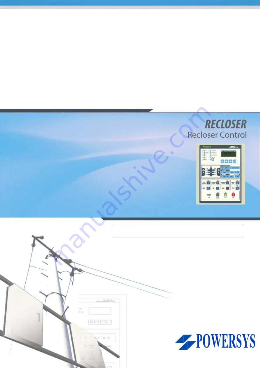
Page 1: ...User Manual Document Version 1 5 Feb 28 2019 http powersys kr http www powersys kr...

Page 2: ...Revision Date Remark 1 0 2013 10 08 the first edition 1 1 2015 08 03 the first update 1 2 2017 01 01 the second update 1 3 2017 10 01 the third update 1 4 2018 02 07 the fourth update 1 5 2019 02 28...

Page 3: ...threatening when you touch it directly The setting should be done along the distribution line configuration The machine shows wrong information or malfunction caused by a different setting from the di...

Page 4: ...of each part 18 4 2 LCD Control and Setting 21 4 2 1 Button Function 21 4 2 2 LCD Display during Power Up 22 4 2 3 LCD Menu Operation 23 4 2 4 LCD Menu Items 23 4 3 Order of Installation Test Operatio...

Page 5: ...og Low Alm 55 5 3 14 Misc Config 55 5 4 Communication Menu 56 5 4 1 SCADA Port 56 5 4 2 Modem Control 56 5 4 3 DNP Config 56 5 4 4 IEC101 Config 57 5 4 5 IEC104 Config 58 5 4 6 TCP IP Config 58 5 4 7...

Page 6: ...T 73 9 TC Curve V Z 74 10 TC Curve IEC NI SI 75 11 TC Curve IEEE MI NI 76 12 TC Curve ANSI U8 U2 77 13 TC Curve ES NI VI 78 14 TC Curve KEPCO N1 N4 79 15 TC Curve DEF 1S 10S 80 APPENDIX C Remote Contr...

Page 7: ...e limited Mainly Reclosers which are installed in overhead distribution line provide the measurement of electric current flowing in the distribution line In case of load current occurrence and fault d...

Page 8: ...ch Open Close control Battery Test control Preparatory control State Monitoring Function Recloser Open Close status Handle locked status Gas pressure low status option External AC low status Battery o...

Page 9: ...g company supplied S W Self diagnosis and Backup functions during power off EPIC R300 operates self diagnosis such as CPU check memory error diagnosis I O diagnosis and control power diagnosis It save...

Page 10: ...t Biased Debounce Delay 1 500ms Control contact Photomos Normal contact 100mA 250VAC 5A 250VAC 2EA 4EA 8EA option Purpose Recloser Open Close Purpose Battery Test Spare Channel Rating input Input burd...

Page 11: ...0V 100M Dielectric Withstand AC 60Hz 2000V 1Min Impulse IEC60255 5 6kV Current IEC60255 5 4kV Voltage Power DIO High Frequency Disturbance IEC60255 22 1 2 5kV EFT Burst IEC60255 22 4 Class A 4kV Radia...

Page 12: ...nsmission Enable Disable Unsolicited Response for each class Save Event which is not transmitted IEC60870 5 101 Protocol support single character NACK Regular update about measurement data capable to...

Page 13: ...Accuracy Range Voltage 1 40kV Including PT ratio Current 1 12 000A Including CT ratio kW kVar kVA 2 0 99MW Power Factor 2 0 1 Frequency 0 01Hz 45 65Hz kWh kVarh 2 0 999999999kW THD 2 0 200 Items Spec...

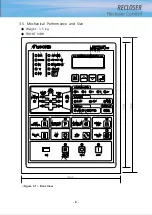
Page 14: ...8 3 5 Mechanical Performance and Size Weight 3 5 kg FRONT VIEW Figure 3 1 Front View...

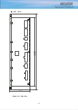
Page 15: ...9 SIDE VIEW 343 00 310 00 91 00 Figure 3 2 Side View...

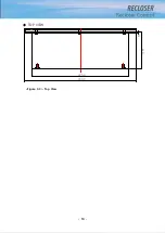
Page 16: ...10 TOP VIEW 84 0 260 0 225 0 1 0 0t Figure 3 3 Top View...

Page 17: ...11 REAR VIEW 180 0 120 0 Figure 3 4 Rear View...

Page 18: ...nal Arrangement RS232C SCADA PORT RS232C SCADA PORT Control Source Connector DI Status Connector DO Control Connector ETHERNETConnector AI Voltage Connector AI Current Connector Figure 3 5 Terminal Ar...

Page 19: ...2 1 DI6 Door Open DI5 Charger Fail DI_COM1 DI4 Batt Low DI3 AC Loss DI2 Close DI1 Open 3 DO Control Connector 12 11 10 9 8 7 DO6 Rec Close DO6 Rec Close DO4 DO4 DO3 Bat Test DO3 Bat Test 6 5 4 3 2 1 D...

Page 20: ...DI6 Door Open DO1 Open IA IB IC Icom IN 0 IN 0 DO1 Open DO3 Bat Test DO3 Bat Test DO2 Close DO4 DO2 Close DO4 DO5 DO6 DO5 DO6 DI7 HandleLock DI8 GasLow DI_COM1 DI9 Spare1 DI_COM2 DI10 Spare2 DI_COM3 V...

Page 21: ...15 Assembly Drawing INTERNAL PANEL DOOR VENTILATOR MODEM CABLE HOLE MS CONNECTOR 130 Figure 3 7 Assembly Drawing...

Page 22: ...16 Controller PCB 215 00 103 90 121 10 112 50 112 50 235 00 205 00 Figure 3 8 Controller PCB...

Page 23: ...17 Battery Check PCB Figure 3 9 Battery Check PCB 5 0 90 0 50 0 20 0 25 0 25 0 20 0 5 0 5 0 50 0 10 0 27 0 R5 5 R7 0 87 0 100 0...

Page 24: ...hows CPU s operation state Error LED LED which shows device s diagnosis fail AC Power LED LED which shows external power Battery Low LED which shows low battery voltage Handle Lock LED which show Recl...

Page 25: ...tribution line s source and whether it is load s voltage and whether it is synchronous Live Source LED LED which shows whether it supplies voltage on source side Live Load LED LED which shows whether...

Page 26: ...on elements for ground overcurrent and SEF is restricted 10 Fault Reset Button It is a button to reset fault and diagnosis signal LED It reset actual fault information with LED 11 Battery Test Button...

Page 27: ...ible to operate on local In order for local control push the button to turn off REMOTE LED Then operate at the local as using OPEN CLOSE button on the side o OPEN Button It is a button to open Reclose...

Page 28: ...button you can move to the main measurement menu which shows the measured value of current and voltage The menu items for Recloser s operation state are as follows SeqN Current reclosing counts R C S...

Page 29: ...e reactive energy Voltage Current Voltage and current s symmetrical component THD Voltage and current s total harmonic distortion Phase Diff Voltage and current s phase difference Reset SW Count Power...

Page 30: ...se Set phase fault operation functions Save Set Save the operation setting Block Flt Pickup Cold Load Multi A multiplier to prevent the mis recognizing as a fault by increasing a multiply of pick up l...

Page 31: ...time HCT Level Set operating value at high current trip level HCT Time Set operating time at high current trip time Func In Use Set phase fault operation functions Save Set Save the operation setting...

Page 32: ...Op Angle Set SEF operating angle Op Time Set SEF operating time Save Set Save the operation setting Trip Reclose Phase Rec Count Phase Oper Cnt Set phase fault sequence operating counts Phase Fast Cn...

Page 33: ...ne function is available Save Set save open line set value Sync Check Phase Off Set sync check phase difference permission setting Delay Time Set sync check phase difference delay time setting Use Fun...

Page 34: ...nterlock set value Loop Automation Loop Selection Select operating mode for the recloser Deadbus Open Time Set open time for determining distribution line s dead line state Tie Sw Open Time Set Open t...

Page 35: ...ime for Voltage Sensor Fail I Cut Level Set level for current cutting V Cut Level Set level for voltage cutting Save Config Save analog configuration setting DI Debou nce Time DI1 DI10 Set DI1 10 debo...

Page 36: ...pickup level for sag Sag Time Set operation time for sag Swell Level Set pickup level for swell Swell Time Set operation time for swell Interrupt Level Set pickup level for interruption Interrupt Tim...

Page 37: ...r door open DI6 AC POWER LED Set condition of AC POWER LED On DI3 Insulator Type Set type of insulator Save Confg Save config set value for Misc config Communica tion SCADA Port Baud Rate Set Baud rat...

Page 38: ...Common Addr Size Set common address size IOA Size Set Information Object address size COT Size Set COT address size Time Format Select Time Format CP24 CP56 or NO Single Character N ACK Set 1 characte...

Page 39: ...pt delay time Max Attempts Set dial max attempt Save PSTN Set Save PSTN related setting PPP Config Our IP Addr Set our IP address Their IP Addr Set their IP address DNS1 IP Addr Set DNS1 IP address DN...

Page 40: ...diagnosis and status information Figure 5 2 Display Menu 1 Power Active Reactive Apparent Power Power Factor Frequency display 2 Energy Active Reactive Energy display kWh If it is over 999999999kWh t...

Page 41: ...ach phase VI 9 DI Status DI Status display it shows 4 items at once In order to see the next item use Up Down Key to move Display items are below Open Close Handle Lock External AC Fail Over Discharge...

Page 42: ...le of FI If there is a fault on distribution line protection device CB Recloser does tripping to protect the system Then EPIC R300 Feeder RTU operates Protection function to detect the fault through w...

Page 43: ...FI reset button on the front or it is reset with transmitted FI reset order in remote R300 is designed to generate FI not only for the case that R300 becomes tripped itself against a fault but also t...

Page 44: ...delay curve condition Delay Min Resp 0 00 1 00 0 00 0 01 sec Set minimum operating response time under delay curve condition Delay Reset Time 0 00 1 00 0 00 0 01 sec Set delay reset time of definite...

Page 45: ...ings These conditions can exists for an extended period and must not be interpreted as a fault In other words this function is recognized as Cold load circumstance when no current measured in the Recl...

Page 46: ...6 F u n c I n U s e 1 7 S a v e S e t P i c k u p L e v e l S E T 4 0 0 A 1 0 2 0 0 0 A 1 A 40 6 Inrush Restraint When the circuit breaker is putted in order to supply the electricity to a load Inrush...

Page 47: ...t 5 2 4 Ground Fault In order to detect ground fault setting items and ranges are like below Table 5 2 Detecting ground fault Category Item Range Default Step Unit Explanation Op Level Time Pickup Lev...

Page 48: ...A Set operating value at high current trip level HCT Time 0 01 1 0 04 0 01 sec Set operating time at high current trip time Func In Use NO YES YES Set phase fault operation functions Block flt Pickup...

Page 49: ...g the Single Shot setting time then it goes to trip and locked out 5 Sequence Coordination When operating with 2 or more Recloser connected in series in distribution line in order to prevent the opera...

Page 50: ...s to delay action in the same way with load Recloser If the reclosing function is restrained the Sequence Coordination function does not work The following rules apply to the Sequence coordination 1 A...

Page 51: ...30 1 sec Set reclosing return time SEF Reclose Time SEF Rec Time 1st 0 3 180 2 0 0 1 sec Set 1st SEF reclosing operation time SEF Rec Time 2nd 1 180 10 1 sec Set 2nd SEF reclosing operation time SEF...

Page 52: ...in operating information and it transmits to the host system over the communication 7 Under Frequency Settings associated with low frequency protection If you select 3 Use Func as TRIP when low frequ...

Page 53: ...h cases that trip by protection elements and remote operation loop control function is automatically stopped 2 Mid point recloser Protection elements are generally operate when downstream fault occurs...

Page 54: ...closer closes when the voltage is supplied to both side 6 Tie recloser opens when the voltage is supplied to both ends Table 5 5 Auxiliary Function Category Item Range Default Step Unit Explanation Op...

Page 55: ...is available Under Frequency U F Pickup 47 59 98 49 8 0 01 Hz Set pickup level for under frequency U F Op Time 0 1 60 1 0 1 sec Set operation time for under frequency Use Func OFF ALM TRIP OFF Set whe...

Page 56: ...tion line s connection Frequency 50 60 60Hz Distribution line s frequency Rated Voltage 3 8 21 13 2 0 01 kV Distribution line s rated voltage CT ratio 100 2000 1000 1 CT ratio NCT ratio 100 2000 1000...

Page 57: ...own Key Press Enter Key to check If you want to cancel the changed set value press M Key 4 After change choose 18 Save Config to save the set value in backup memory and come out from the item Then the...

Page 58: ...menu to adjust analog voltage current volume gain EPIC R300 is set in calibration about voltage current signal input from factory However if measuring value is different because of external sensor s...

Page 59: ...t Explanation Check Day 1 31 1 1 day Set auto checking day for battery Check Hour 0 23 0 1 hour Set auto checking hour for battery Check Minute 0 59 0 1 minute Set auto checking minute for battery opt...

Page 60: ...tion time for sag Swell Level 101 150 120 1 Set pickup level for swell Swell Time 0 02 10 1 0 0 01 sec Set operation time for swell Interrupt Level 10 50 10 1 Set pickup level for interruption Interru...

Page 61: ...Phase Voltage 1 38000 13200 1 V Set phase voltage level for Analog High Alarm function System Power 1 54000 5280 1 kV Set system power level for Analog High Alarm function Enable High Alarm Disable En...

Page 62: ...nd modem Table 5 20 Modem Control The way to set is identical with 5 3 1 5 4 3 DNP Config It is a menu to set DNP3 0 communication related items Item Range Default Step Unit Explanation Baud Rate 1200...

Page 63: ...etting Frame Interval 10 500 20 10 ms If D L timeout confirm is NO choose link frame s interval DNP Port Num 0 65534 20000 1 Set DNP TCP Port Num Cls Evt when RST Disable Enabl e Disable Select whethe...

Page 64: ...Default Step Unit Explanation Conn Timeout t0 1 255 30 1 sec Set connection timeout APDU Timeout t1 1 255 15 1 sec Set APDU timeout Ack Timeout t2 1 255 10 1 sec Set ack timeout Test Period t3 1 255...

Page 65: ...2 7 T i m e 1 4 3 0 2 6 E d i t 2 0 1 3 0 9 2 7 T i m e 1 4 3 0 2 6 Figure 5 18 Time Set year 2 To change the month press Enter Key Then the cursor blinks Press Up Down Key to change N o w 2 0 1 2 0...

Page 66: ...hour 5 To change the minute press Enter Key Then the cursor blinks Press Up Down Key to change N o w 2 0 1 2 0 9 2 7 T i m e 1 4 3 0 2 6 E d i t 2 0 1 3 1 0 2 9 T i m e 1 5 2 2 2 6 Figure 5 22 Time S...

Page 67: ...e below Table 5 30 Event View Menu Event Items Description Max Event Num Fault Event Save Fault Event history 512 Op Event Save Operation Event history save operation history about Power On DO DI oper...

Page 68: ...formation Configuration File Format The configuration file is an ASCII text file that contains the information necessary to interpret the data dat file The configuration file will have the same filena...

Page 69: ...63...

Page 70: ...dat file contains the sample number time stamp and data values of each channel for each sample in the file The data file has the same name as the configuration file but with a dat file extension and c...

Page 71: ...65 Example configuration file...

Page 72: ...No 31 32 33 34 35 36 37 38 39 40 TC Curve 16 18 IEC NI IEC VI IEC EI IEC LI IEC SI IEEE MI IEEE VI IEEE EI No 41 42 43 44 45 46 47 48 49 50 TC Curve IEEE NI ANSI U2 ANSI U8 ES NI ES VI KEPCO N1 KEPCO...

Page 73: ...67 2 TC Curve 1 4 100 101 10 1 100 101 102 Time sec Current In Multiplies of Setting 1 2 3 4...

Page 74: ...68 3 TC Curve 5 8 100 101 10 1 100 101 102 Time sec Current In Multiplies of Setting 5 6 7 8...

Page 75: ...69 4 TC Curve 8 13 100 101 10 1 100 101 102 Time sec Current In Multiplies of Setting 8 9 11 13...

Page 76: ...70 5 TC Curve 14 18 100 101 10 1 100 101 102 Time sec Current In Multiplies of Setting 14 15 16 18...

Page 77: ...71 6 TC Curve A D 100 101 10 1 100 101 102 Time sec Current In Multiplies of Setting A B C D...

Page 78: ...72 7 TC Curve E M 100 101 10 1 100 101 102 Time sec Current In Multiplies of Setting E K L M...

Page 79: ...73 8 TC Curve N T 100 101 10 1 100 101 102 Time sec Current In Multiplies of Setting N P R T...

Page 80: ...74 9 TC Curve V Z 100 101 10 1 100 101 102 Time sec Current In Multiplies of Setting V W Y Z...

Page 81: ...75 10 TC Curve IEC NI SI 100 101 10 1 100 101 102 103 104 IEC NI IEC VI IEC EI IEC LI IEC SI Current In Multiplies of Setting Time sec...

Page 82: ...76 11 TC Curve IEEE MI NI 100 101 10 1 100 101 102 103 IEEE MI IEEE VI IEEE EI IEEE NI Current In Multiplies of Setting Time sec...

Page 83: ...77 12 TC Curve ANSI U8 U2 100 101 10 1 100 101 102 103 ANSI U8 ANSI U2 Current In Multiplies of Setting Time sec...

Page 84: ...78 13 TC Curve ES NI VI 100 101 10 1 100 101 102 ES NI ES VI Current In Multiplies of Setting Time sec...

Page 85: ...79 14 TC Curve KEPCO N1 N4 100 101 10 1 100 101 102 Time sec Current In Multiplies of Setting N1 N2 N3 N4...

Page 86: ...80 15 TC Curve DEF 1S 10S 100 101 10 1 100 101 DEF 1S DEF 10S Current In Multiplies of Setting Time sec...

Page 87: ...ith the supplied remote control IR receiver is located on the bottom of the recloser control box You can point the supplied remote control to the IR receiver and then enter the button The remote contr...

Reviews: