background image

CONTENTS

(click on a topic to view)

Congratulations

System Tuning

Features and Specifications

System Tuning

Detachable Control Panel

Frequency Distribution

Installation / Mounting

System 1

Wiring

System 2

Wiring

Troubleshooting

Functions

Block Diagram

Parametric Operation

Control Panel

System Tuning

Warranty

PMQ 210  

T

en Band P

arametric Equaliz

er

  O

WNERS MANU

AL 

 PO

WER

 CLASS

TM

Summary of Contents for PMQ-210

Page 1: ...ations System Tuning Detachable Control Panel Frequency Distribution Installation Mounting System 1 Wiring System 2 Wiring Troubleshooting Functions Block Diagram Parametric Operation Control Panel System Tuning Warranty PMQ 210 Ten Band Parametric Equalizer OWNERS MANUAL POWER CLASS TM ...

Page 2: ...y reliability and value This PrecisionPower product reflects our commitment to offer you unparalleled versatility and quality for years of dependable service and listening enjoyment S ervice Do not attempt to service PrecisionPower products yourself Performing exploratory surgery on your audio equipment yourself will void the warranty Many parts of your PrecisionPower gear are custom built to our ...

Page 3: ...output connectors PWM Power Supply L E D power indicator Designed and Handcrafted in the U S A Specifications Signal to Noise Ratio 102 dB Total Harmonic Distortion 1kHz 1VRMS 0 017 Cut Boost Range 12 dB Input Gain 0 dB Q Range 1 5 4 Attenuation 12 dB Maximum Input Voltage attenuation out 8 VRMS Maximum Input Voltage attenuation in 16 VRMS Maximum Output 10 kΩ Load 8 VRMS Frequency Response 0 to 5...

Page 4: ...en head screw located to the right of the thumb notch on the front bezel that holds the main control panel to the docking bay and carefully remove the main control panel You will notice that it is connected to the docking bay via a short eight conductor cable Make sure that the power is off Remove the control panel disconnect the short cord at both ends and then replace it with the 20 ft cable sup...

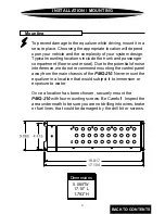
Page 5: ...ise interference we do not recommend mounting the control panel away from the main chassis of the PMQ 210 Never mount the equalizer in a location that would subject it to immersion or exposure to water Once a location has been chosen securely mount the PMQ 210 with four mounting screws Be Careful Inspect the area underneath to be sure you are not drilling into wires brake or fuel lines that could ...

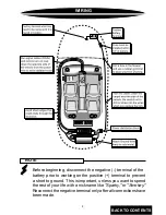
Page 6: ...eginning disconnect the negative terminal of the battery prior to working on the positive terminal to prevent a short to ground This is important unless you want to spend the rest of your life with a nickname like Sparky or Smokey Reconnect the negative terminal only after all connections have been made NOTE BACK TO CONTENTS ...

Page 7: ...ldering this connection After the connection is complete coat the area with silicone or some similar material to prevent rust from developing Finally the remote wire needs to run to the power antenna or amplifier remote lead of the head unit This wire supplies a 12 volt signal to the PMQ 210 when the main system is activated Once you have routed the power ground and remote wires through the vehicl...

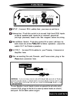
Page 8: ...nPower dealer or call 1 800 62POWER INPUT Connect RCA cables from your source unit here Attenuation Push this switch in to accept high level RCA inputs or direct speaker lead inputs from common grounded not high powered head units See diagram below for wiring Stereo Mono Switch Push this switch IN to send Left Input to both channels of the PMQ 210 for Mono operation Leave the switch OUT for Stereo...

Page 9: ...s to be able to use one effectively On the face of the detachable control panel are ten sets of three controls each On the top row are the frequency selection controls which allow you to dial in the exact frequencies in need of adjustment There are ten overlapping ranges that cover the entire audio spectrum The second row consists of the Q adjustment from 1 5 to 4 for each frequency selected Q is ...

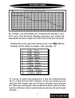
Page 10: ... 3dB per step and set the speed of the RTA s readout to medium Turn on your system and start the pink noise Raise or lower the volume until you can see all or most of your frequency response on the RTA scale a little above or below is OK Make sure all of the equalizer s Cut Boost controls are at zero and look at the RTA screen 4 You are trying to achieve a target frequency response or curve that r...

Page 11: ...he Q control fully clockwise to 4 and the Cut Boost all the way to 12dB Now turn the Frequency control up and down as you watch the RTA display and you will see a tall peak move right and left When this moving peak lines up with the peak you want to control turn the Cut Boost control counterclockwise and you will see the peak diminish Reading from left to right when looking at your new PMQ 210 the...

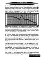
Page 12: ... the new curve you are making to the system in an unequalized state by using the defeat switch on the lower left corner of the control panel 9 Play your favorite music If the sound isn t what you re looking for go back to the pink noise and smoothly adjust your curve for more bass less midrange or whatever you think will correct the sound Remember that this is your system don t let someone else te...

Page 13: ...bone tuba soprano sax tenor sax clarinet oboe flute piano synthesizer female vocal range male vocal range tympani kick drum tom drum snare drum cymbals electric bass FUNDAMENTAL NOTE HARMONIC OR OVERTONE 25 50 100 200 400 800 1 6 3 2 6 4 12 8 20K FREQUENCY DISTRIBUTION BACK TO CONTENTS ...

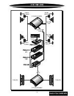
Page 14: ...b Cut Boo st 12d b 1 2db Cut Boo st 12d b 1 2db De fea t EQ Ground Remo te Powe r Inp ut Outpu t ster eo out mon o in atte nua tion 12d B in Pre cisi onPow er Q 4 1 5 Q 4 1 5 Q 4 1 5 Q 4 1 5 Q 4 1 5 Q 4 1 5 Q 4 1 5 Q 4 1 5 Q 4 1 5 Q 4 1 5 PM Q 2 10 9 37 KH z 15 7 5KH z H L 4KH z 9 37K Hz H L 1 95 KH z 4 5Kh z H L 940 Hz 1 25 KH z H L 330 Hz 1KH z H L 160 Hz 550 Hz H L 80H z 26 0Hz H L 40H z 13 0Hz...

Page 15: ...b 1 2db Cut Boo st 12d b 1 2db Cut Boo st 12d b 1 2db Cut Boo st 12d b 1 2db Cut Boo st 12d b 1 2db Cut Boo st 12d b 1 2db Cut Boo st 12d b 1 2db De fea t EQ Ground Remo te Power Inp ut Outpu t ster eo out mon o in atte nua tion 12d B in Pre cisi onPow er Pre cisi onPow er EPX 2 23 Mad e in USA Po w er PEle ctron ic Cros sove r Le f t Ph ase o ø Rig ht Pha se o ø Pre cis ion Po we r Inp ut Ground ...

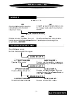
Page 16: ...k head unit and amplifiers Is the LED lit SOUND IS NOW IN OPPOSITE CHANNEL Reverse RCA inputs SOUND IS NOW IN OPPOSITE CHANNEL Reverse RCAs at head unit SAME CHANNEL Problem is in the Equalizer See your local Authorized PowerPower Dealer or call 1 800 62POWER SOUND IS NOW IN SAME CHANNEL Problem is in the RCA cables OPPOSITE CHANNEL Problem is in the head unit SAME CHANNEL Problem is in the amplif...

Page 17: ...15 BLOCK DIAGRAM BACK TO CONTENTS ...

Page 18: ...16 CONTROL PANEL BACK TO CONTENTS ...

Page 19: ...Refer to original packaging for the serial number of your component speakers 5 The provisions of this warranty shall not apply to any PrecisionPower product used for a purpose for which it is not designed which has been repaired or altered in any way or which has been connected installed or adjusted other than in accordance with the instructions furnished in PrecisionPower s owner s manual Nor sha...

Reviews: