background image

 9.55 Treadmill

Page 1

9.55 Treadmill

Warning:

 This service manual is for use by Precor trained service providers only.

If you are not a Precor Trained Servicer, you must not attempt to service any Precor Product;               

Call your dealer for service.

This document contains information required to perform the majority of troubleshooting, and 
replacement procedures required to repair and maintain this product. 

This document contains general product information, software diagnostic procedures (when 
available), preventative maintenance procedures, inspection and adjustment procedures, 
troubleshooting procedures, replacement procedures and electrical block and wiring diagrams.

To move directly to a procedure, click the appropriate procedure in the bookmark section to the 
left of this page. You may “drag” the separator bar between this page and the bookmark section 
to change the size of the page being viewed.

                                                                 © 2003 Precor Incorporated
                                   Unauthorized Reproduction and Distribution Prohibited By Law

Summary of Contents for 9.55

Page 1: ...is product This document contains general product information software diagnostic procedures when available preventative maintenance procedures inspection and adjustment procedures troubleshooting procedures replacement procedures and electrical block and wiring diagrams To move directly to a procedure click the appropriate procedure in the bookmark section to the left of this page You may drag th...

Page 2: ...ns the procedures you need to access the diagnostic features on this treadmill Section Three Checking Treadmill Operation This section provides you with a quick way of checking treadmill operation Check treadmill operation at the end of a maintenance procedure and when it is necessary to ensure that the treadmill is operating properly Section Four Inspection and Adjustment Procedures Perform inspe...

Page 3: ...l Specifications Length 84 inches 213 cm Width Handrails 36 75 inches 93 cm Base 33 75 inches 86 cm Height 55 inches 140 cm Running surface 26 inches by 60 inches 51 cm by 152 cm Motor 2 hp continuous duty DC Speed 0 5 to 12 mph 0 8 to 19 kph 10 mph is equivalent to a 6 minute mile Incline 0 to 12 grade Power 120 Vac 50 60 Hz 20 amp 240 Vac 50 60 Hz 20 amp Weight 350 lbs 158 kg Shipping Weight 460...

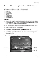
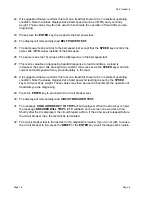
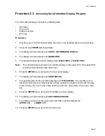
Page 4: ...ey number 4 and is located directly below the QUICK START key The QUICK START key is not part of the numbering sequence 2 Plug the power cord into the wall outlet then turn on the treadmill with the circuit breaker 3 Press keys RESET 5 1 7 6 5 7 6 1 sequentially 4 The display will momentarily read DIAGS HARDWARE VALIDATION 5 The display will momentarily read DISPLAY TEST and then illuminate every ...

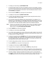
Page 5: ...ge NO HEART RATE RECEIVER 12 Press the ENTER key to proceed to the lift test 13 The display will momentarily read LIFT TEST 14 Two numbers will be displayed the percent of lift and A D number related to the current lift position The A D analog to digital number represents the lift potentiometer reading The A D number will be in the range of 0 to 255 15 The lift may be operated using the INCLINE ke...

Page 6: ... keys and the current and belt speed will vary proportionately to the load 28 It is suggested that you perform this test on a treadmill known to be in excellent operating condition Note the values displayed at a fixed power bit reading as set by the SPEED keys and your body weight Those values may then be used to benchmark the operation of treadmills you are diagnosing 29 Press the ENTER key to pr...

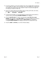
Page 7: ...in non volatile memory on the upper PCA If the upper PCA is replaced the odometer data will be lost 6 Press the ENTER key to proceed to the hour meter display 7 The display will momentarily read HOUR METER 8 The operating time of the unit will be displayed as 12345 HOURS The operating time is defined as total amount of time that the unit has operated in program modes with the drive motor running T...

Page 8: ...hour meter when the error occurred The errors are displayed as 1 ER20 1234567 MI 12345 HRS 15 The arrows keys will allow you to scroll through the log When the first unused position is reached in the log the message NO MORE ERRORS will be displayed 16 When the QUICK START key is held for 2 seconds the message HOLD TO CLEAR ERRORS will be displayed If the QUICK START key is held for an additional 2...

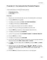
Page 9: ...he currently displayed measurement unit 8 The display will momentarily read PASSWORD 9 Use the keys to select either PASSWORD ENABLED or PASSWORD DISABLED 10 Press the ENTER key to continue 11 The display will momentarily read USER NAME 12 Up to four user names may be entered If user names have not been previously entered the default user names will be USER1 USER2 USER3 and USER4 13 The USER1 name...

Page 10: ...d the following information Model and serial number Software version number Program number running when the problem occurred A description of a What happened or failed to happen b The action taken by the user just before the problem occurred c Problem related information such as how far into the program the problem occurred the work level being used when the problem occurred etc The frequency of o...

Page 11: ...D s on the electronic console Make sure that each LED lights as the in formation corresponding to that LED is displayed on the electronic console 3 If during step 1c squeaking noises associated with the running deck were heard check the lubrication of the running deck studs If necessary apply silicon grease to all of the running deck studs 3 Press the STOP key When the treadmill comes to a stop vi...

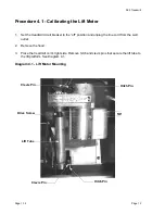
Page 12: ... the off position and unplug the line cord from the wall outlet 2 Remove the hood 3 Place the treadmill on it s right side Remove hitch and clevis pins that secure the lift tube to the lift platform See Diagram 4 1 Diagram 4 1 Lift Motor Mounting Hitch Pin 5 8 Hitch Pin Clevis Pin Lift Tube Drive Screw Clevis Pin ...

Page 13: ...ics mode 7 Set the treadmill circuit breaker in the off position unplug the line cord from the wall outlet 8 Rotate the lift tube clockwise by hand as far as possible Then rotate the lift tube counter clockwise until the distance from the top of the lift tube to the lift motor is 5 8 inch See Diagram 4 1 While rotating the lift tube be sure the lift motor drive screw does not rotate If the drive s...

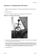
Page 14: ... The gauge should read approximately 80 inch pounds The drive belt tension is acceptable if it is in the range of 70 to 90 inch pounds 5 If the drive belt tension is less than 70 or greater than 90 inch pounds adjust the drive belt adjustment bolt until the belt gauge reads approximately 80 inch pounds See Diagram 4 3 Momentarily remove the drive belt tension gauge from the drive belt Replace the ...

Page 15: ...age 15 Diagram 4 3 Drive Belt Adjustment Bolt 7 Plug the line cord into the wall outlet and set the treadmill circuit breaker in the on position 8 Check treadmill operation per Section 3 Drive Motor Drive Belt Adj Bolt ...

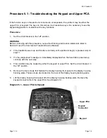
Page 16: ...rvice Manual 2 If the treadmill powers up and functions normally until a particular key s is pressed skip to step 11 3 If a key depressed message is immediately displayed when the treadmill is powered up continue with the next step 4 This condition may be caused by either the keypad or upper PCA Set the circuit breaker in the off position 5 Remove the four screws that fastens the display housing f...

Page 17: ...ostics program per procedure 2 1 If the key s necessary to access the diagnostic program is not functioning skip to step 14 12 Test the keypad per Procedure 2 1 step 6 13 If all of the keys test good the problem may be user error or a key function that is normally disabled during a particular user program 14 If one or more keys do not function correctly either the keypad display housing or upper P...

Page 18: ...arting position calibration See Procedure 4 1 subsequent motor movement is tracked via the potentiometer resistance reading Note All resistance measurements must be performed with power removed from the treadmill Performing resistance measurements with voltage applied may damage your ohmmeter Procedure 1 If the lift motor operates but creates a lift error error 40 or 42 go to step 16 If the lift m...

Page 19: ...t Remove the lift motor connector from the J5 connector on the lower logic PCA Visually inspect the lift motor connector for broken or improperly crimped connections Using an ohmmeter read the resistance between terminals 1 4 and between terminals 3 4 Both readings should be approximately 15 Ω If either reading is open or very high resistance replace the lift motor per Procedure 6 1 11 Set the tre...

Page 20: ...erly crimped connections Using an ohmmeter measure between terminals 1 3 1 2 and 2 3 of the lift motor connector Terminals 1 and 3 should read approximately 1 KΩ The sum of the two readings between terminals 2 3 and 1 2 should total approximately 1 KΩ If either reading is open or very high resistance replace the lift motor per Procedure 6 1 17 If the resistance measurements in step 16 are normal t...

Page 21: ...will operate perhaps only briefly before a speed related error occurs errors 20 26 1 Set the treadmill circuit breaker in the on position Using a DC voltmeter measure the voltage between terminal 3 of J2 green wire and terminal 4 of J2 black wire on the lower logic PCA Slowly rotate the drive motor flywheel The voltage should read approximately 5 Vdc when a flywheel lobe is between the speed senso...

Page 22: ...nsor output is good but a speed error occurs There are two potential causes for this condition They are upper PCA or lower logic PCA There are no good means of troubleshooting these components other than substituting known good components Replace only one component at a time If the component that you replaced does not correct the problem replace the original component Try substituting the lower lo...

Page 23: ... breaker with a capacity of less than 20 amps the A C circuit must be corrected to be a 20 amp dedicated circuit before any reliable troubleshooting can be performed on the treadmill More importantly a non dedicated circuit may constitute a safety hazard to the treadmill operator 120 Vac Systems 120 Vac distribution systems utilize a single pole circuit breaker hot lead and a neutral lead connecte...

Page 24: ...amp circuit breaker If the circuit breaker is greater than 20 amps the circuit breaker should be replaced with a 20 amp circuit breaker If the circuit breaker is less than 20 amps the circuit breaker must be replaced with a 20 amp circuit breaker and the wiring from the A C distribution must be capable of safely handing 20 amps If the A C wiring is under sized it must be replaced with wire capable...

Page 25: ...teps 4 7 7 Remove the lower PCA per Procedure 6 4 steps 1 7 8 Remove the defective lift motor as follows remove the screw that fastens the frame ground wire green with yellow stripe to the treadmill frame Remove the hitch and clevis pins from the top and bottom of the lift motor Remove the lift motor from the treadmill 9 Set the calibrated lift motor in its mounting position Replace the upper clev...

Page 26: ...low the lift tube to rotate If the lift tube rotates the lift motor must be re calibrated per Procedure 4 1 4 Remove the four bolts 2 each side that fasten the lift platform to the treadmill frame See Diagram 6 1 Remove the lift platform from the treadmill Diagram 6 1 Lift Platform Mounting 5 Set the replacement lift platform in it s mounting position Start all four lift platform bolts Securely ti...

Page 27: ...ced with the version 2 lower PCA assembly Version 1 units can be identified in two ways the lower PCA assembly has two separate PCA s mounted on it and the serial number will indicate the unit was manufactured prior to July 2 2001 To replace the lower PCA on a version 1 9 55 treadmills order 1 59036 101 9 55 lower PCA retrofit kit The kit comes complete with all necessary parts and installation in...

Page 28: ...replaced with the version 2 lower PCA assembly Version 1 units can be identified in two ways the lower PCA assembly has two separate PCA s mounted on it and the serial number will indicate the unit was manufactured prior to July 2 2001 To replace the lower PCA on a version 1 9 55 treadmills order 1 59036 101 9 55 lower PCA retrofit kit The kit comes complete with all necessary parts and installati...

Page 29: ...ing correctly routed and tied down Diagram 6 6 Lower PCA Mounting version 2 3 Disconnect all of the lower PCA wiring noted in step 2 from the lower PCA 4 Remove the left rear mounting screw left front mounting screw and two right side mounting screws 5 Remove the lower PCA from the treadmill Fasten the lower PCA with the three screws and nut removed in step 4 6 Replace all of the lower PCA wiring ...

Page 30: ...e M1 connector and the M6 connector Caution If the treadmill being serviced operates on 240 Vac the jumper in step 12 must not be installed If the jumper is installed and the treadmill is operated on 240 Vac the lower power PCA will be operated on double the intended voltage Damage to the lower power PCA will result 8 Set the treadmill circuit breaker in the on position and check treadmill operati...

Page 31: ... treadmill drive motor See Diagram 6 7 Diagram 6 7 Speed Sensor Mounting 5 Remove the mounting bracket from the drive motor 6 Remove the two screws that fasten the speed sensor to the bracket 7 Mount the replacement speed sensor on the mounting bracket with the screws removed in step 6 8 Mount the bracket on the drive motor with the screws removed in step 4 9 Insert the speed sensor plug into the ...

Page 32: ...9 55 Treadmill Page 1 32 Page 32 11 Set the treadmill circuit breaker in the on position and check treadmill operation per Procedure 3 ...

Page 33: ...e four bolts that fasten the drive motor onto it s mounting plate Remove the drive motor from the treadmill 7 Remove the screws that mount the speed sensor and bracket onto the drive motor see Diagram 6 7 8 Mount the speed sensor and bracket on the replacement drive motor using the screws removed in step 7 9 Remove the four screws that fasten the drive motor cooling fan onto the drive motor See Di...

Page 34: ...9 55 Treadmill Page 1 34 Page 34 15 Re install the hood 16 Check treadmill operation per Procedure 3 ...

Page 35: ...he treadmill See Diagram 6 8 Diagram 6 8 Circuit Breaker Mounting Panel 3 Disconnect all of the wiring from the circuit breaker 4 Remove the circuit breaker mounting screws Remove the circuit breaker from the treadmill 5 Set the replacement circuit breaker in its mounting position Fasten the circuit breaker to the circuit breaker mounting panel using the screws removed in step 4 6 Connect the wiri...

Page 36: ...iagram 6 9 Circuit Breaker Wiring 7 Set the circuit breaker mounting panel in it s mounting position Fasten the circuit breaker mounting panel to the treadmill using the screws removed in step 2 8 Check treadmill operation per Section 3 ...

Page 37: ... 4 Remove the screws that fasten the line filter to the circuit breaker mounting panel 5 Set the replacement line filter in it s mounting position Fasten the line filter to the circuit breaker mounting panel with the screws removed in step 4 6 Connect the wiring to the line filter per Diagram 6 10 Diagram 6 10 Line Filter Wiring 7 Set the circuit breaker mounting panel in it s mounting position Fa...

Page 38: ...its or from the circuit breaker 240 Vac units 5 Remove the line cord s strain relief mounting nut and remove the line cord 6 Remove the mounting nut from the replacement line cord and feed the line cord through the circuit breaker mounting plate Fasten the line cord to the circuit breaker mounting plate with the nut removed in the previous step 7 Connect the line cord s brown wire to the circuit b...

Page 39: ...per Procedure 6 7 steps 2 8 4 Remove the four screws that mount the drive motor cooling fan to the drive motor See Diagram 6 11 Diagram 6 11 Drive Motor Cooling Fan Mounting 5 Set the replacement drive motor cooling fan at it s mounting position on the drive motor and fasten it with the hardware removed in step 4 6 Replace the drive motor per Procedure 6 7 steps 11 15 7 Check treadmill operation p...

Page 40: ... wire from the tab on the brush housing Remove the brush spring by depressing the tab on the brush spring 5 Remove the brush from it s brush holder See Diagram 6 12 Diagram 6 12 Drive Motor Brush 6 Slide the replacement brush into the brush holder Be sure that the angled edge of the brush is oriented so that the brush face makes full contact with the motor commutator 7 Reinstall the brush spring a...

Page 41: ...9 55 Treadmill Page 41 9 Repeat 3 8 with remaining drive motor brush 10 Replace the drive motor per Procedure 6 7 steps 11 14 11 Re install the hood 12 Check treadmill operation per Procedure 3 ...

Page 42: ...e PLCC44 Each of these packages should be removed with a proper IC removal tool see the illustrations below 4 The IC s may inserted into their socket by hand by carefully aligning the notch on the IC with the notch on the IC socket and carefully pressing the IC into its socket See the illustrations below for the alignment notches Care must be taken that the IC legs on a DIP28 are all aligned in th...

Page 43: ...9 55 Treadmill Page 43 Wiring Diagram 7 1 9 55 version 1 ...

Page 44: ...9 55 Treadmill Page 1 44 Page 44 Block Diagram 7 2 9 55 120 Vac version 1 Note Fan sense function removed on units manufactured sfter 9 29 2000 ...

Page 45: ...9 55 Treadmill Page 45 Block Diagram 7 3 9 55 240 Vac version1 Note Fan sense function removed on units manufactured sfter 9 29 2000 ...

Page 46: ...9 55 Treadmill Page 1 46 Page 46 Wiring Diagram 7 4 9 55 120 Vac version 2 ...

Page 47: ...9 55 Treadmill Page 47 Wiring Diagram 7 5 9 55 240 Vac version 2 ...

Page 48: ...9 55 Treadmill Page 1 48 Page 48 Block Diagram 7 6 9 55 120 Vac version 2 ...

Page 49: ...9 55 Treadmill Page 49 Block Diagram 7 7 9 55 240 Vac version 2 ...

Reviews: