background image

Service Manual

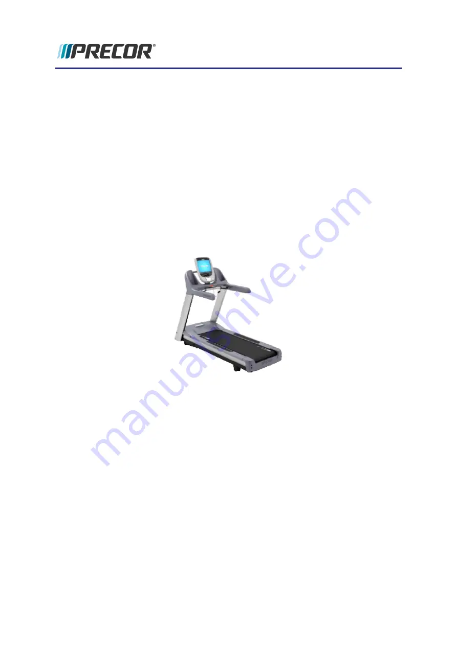
TRM10/GEN06 Treadmill

120 VAC and 240 VAC

Summary of Contents for GEN06 Series C952

Page 1: ...Service Manual TRM10 GEN06 Treadmill 120 VAC and 240 VAC ...

Page 2: ...ication Checklist 9 3 Standard Service Software 10 About 10 Service Access Codes 10 Accessing the Service Software 10 Navigating the Service Software Menus 13 Hardware Validation Diagnostic Tests 51765761 13 Club Parameter Settings 5651565 15 Information Display 65 18 4 Adjustment Procedures 20 Available Adjustment Procedures 20 Drive Belt Tension Alignment Adjustment 21 About 21 Procedure 21 Lift...

Page 3: ...nsor Replacement 32 About 32 Procedure 32 Circuit Breaker Replacement 34 About 34 Procedure 34 Drive Belt Replacement 36 About 36 Procedure 36 Drive Motor Replacement 40 About 40 Procedure 40 Drive Roller Replacement 42 About 42 Procedure 42 End Cap Belt Guard Cover Replacement 46 About 46 Procedure 46 Incline Lift Motor Replacement 48 About 48 Procedure 48 Undefined variable TRM700 16Base Service...

Page 4: ...rd Replacement 59 About 59 Procedure 59 Running Belt and Deck Replacement 61 About 61 Procedure 61 Take Up Roller Replacement 66 About 66 Procedure 66 6 Troubleshooting 68 About 68 Introduction to Treadmill Troubleshooting 68 Validate a customer reported issue 68 Basic Steps 68 Standard Error Codes 70 About 70 Viewing Error Codes 71 Troubleshooting with Error Codes 71 Undefined variable TRM700 16B...

Page 5: ...hooting 89 Input Power and Machine Controls Troubleshooting 90 Running Belt and Deck Troubleshooting 91 Tripped Circuit Breaker 93 7 Preventive Maintenance 96 About 96 Maintenance Schedule 96 Running Belt and Deck Cleaning Procedure 99 8 Theory of Operation 103 About 103 Consoles 103 Treadmill Base Operation 104 System Diagrams 110 System Block Diagram 120 VAC 110 System Wiring Diagram 110 9 Parts...

Page 6: ...Copyright i Appendix B Notices and Safety ii Trademarks ii Intellectual Property ii Warranty ii Safety Instruction ii Safety Notices ii Undefined variable TRM700 16Base ServiceManualTitle vi ...

Page 7: ...is document contains information required to perform troubleshooting and replacement pro cedures required to repair and maintain this equipment including general product information software diagnostic procedures preventative maintenance procedures inspection and adjust ment procedures troubleshooting procedures replacement procedures and system block and wiring diagrams Separate Base Console Serv...

Page 8: ... Troubleshooting on page 68 Theory of Operation on page 103 Undefined variable TRM700 16Base ServiceManualTitle 2 1 Introduction ...

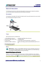
Page 9: ... l US SAE and Metric socket set l Belt Tension Gauge recommended Kent Moore BT 33 73 F l Running belt tension gauge pn PPP00000002000710 Parts IMPORTANT Always purchase OEM replacement parts and hardware from Precor If you use parts not approved by Precor you could void the Precor Limited Warranty Use of parts not approved by Precor may cause injury Exploded View Diagram and Parts List There is a ...

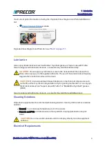
Page 10: ...AUTION Do not use petroleum based lubricants on mechanical components such as the lift as this may result in degradation of nylon gearing mechanisms Use only syn thetic lubricants such as Super Lube with Teflon or Mobile One Synthetic grease RED Use of unapproved lubricants cleaners or solvents may void the treadmill warranty Cleaning Solutions Wipe down equipment with recommended cleaning solutio...

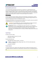
Page 11: ...ate circuit changes CAUTION The treadmill requires a 20 amp individual branch circuit grounded per NEC National Electric Code guidelines or local region electric code IMPORTANT If the AC circuit feeding a treadmill is found to be a non dedicated branch circuit or a circuit equipped with a capacity of less than 20 amps the AC circuit must be corrected before any reliable Troubleshooting can be perf...

Page 12: ...quip the unit with the optional external power supply or have an assistant pedal on the unit while voltage measurements are being taken Because of the danger of working on the unit while it is in motion using the optional external power supply is strongly recommended l On ATM units when the stairarms are in motion the generator will operate and produce potentially hazardous voltages even when the ...

Page 13: ... Remove neck ties and o Do not wear loose clothing See Also Safety Instruction on page ii Safety Notices on page ii Undefined variable TRM700 16Base ServiceManualTitle 7 1 Introduction Safety Guidelines ...

Page 14: ... hold down the QUICK START key until the error is deleted 4 Enter the Hardware Validation Test by entering access code 5 1 7 6 5 7 6 1 a Press either the STOP PAUSE or RESET buttons and then enter 5 1 7 6 5 7 6 1 Note For P80 consoles refer to Accessing the Service Software on page 10 5 Select and run the Display Test the Keypad Test and the Heart Rate Test Verify that each test is successfully co...

Page 15: ... the verification tests Note that on P80 consoles go to the Event Log page to view logged errors see Accessing the Service Software on page 10 Operation Verification Checklist Use this checklist to track that the verification procedure tests were successfully completed and that the treadmill operation has been verified Check record and then clear any errors in the error log Verify that all LEDs fu...

Page 16: ... user interface available information settings etc will vary based on the console model base configuration Make sure to use the information and instructions for your particular con sole application Consoles that support standard service access codes include Standard Consoles P30 console P10 consoles P80 console P20 console Service Access Codes The following table lists the standard service access ...

Page 17: ...service access code using the numeric keypad NOTE The access code must be correctly and quickly entered or the process will abort Restart the process from the beginning if this occurs P20 Consoles To access the service software Undefined variable TRM700 16Base ServiceManualTitle 11 3 Standard Service Software Accessing the Service Software ...

Page 18: ...nue holding down the PAUSE key while pressing the Volume and Channel Up Down keys in the following sequence X pattern to open the service soft ware login page Press hold PAUSE while selecting CH Up Vol Down Vol Up CH Down NOTE Keep the keypad entry interval to greater than 1 second between key presses Key press interval speed faster than 1 second may result in an unsuccessful login l Successful lo...

Page 19: ...consoles The P80 uses the touch screen to view navigate and perform the diagnostic tests Follow on screen prompts to access and complete tests Hardware Validation Diagnostic Tests 51765761 Service Access Code 5 1 7 6 5 7 6 1 see Service Access Codes on page 10 The set of available diagnostic tests will vary based on console model Select console model to view the available diagnostic tests Standard...

Page 20: ...ts and hardware calibration page select test from menu DIAGNOSTIC TEST TEST DESCRIPTION Auto Stop Test Tests the Auto Stop function showing the averaged foot plants and exerciser is detected is not detected function Foot plant averaging delay resets with each speed change Belt Speed Test Tests the belt speed by stepping the speed in 0 1 mph increments and show ing the required drive motor current ...

Page 21: ...bled Enable or disable the Safety Code When enabled the setting requires a password 1234 to be entered to start the unit SELECT LANGUAGE Default English Sets the default language for all workouts on this machine Lan guage for single use workouts can still be set by the user from the workout options SET UNITS Range U S Metric Default U S Sets units of measure to US standard or Metric SET MAX WORKOU...

Page 22: ...ET CUSTOM PROGRAM 1 2 Range ON OFF Default OFF Create a customized workout program residential use Note not available on all models P80 Series Consoles The P80 Club parameters include additional configuration parameters for TV internet con nectivity and Preva Net functionality Refer to the Owner s manual for the complete descrip tion of available Club parameters The P80 Club parameters are located...

Page 23: ...imits MAXIMUM WORKOUT DURATION Range 1 to 240 min NO LIMIT Default 60 min Sets the maximum allowable user workout time per session MAXIMUM PAUSE Range 1 to 300 sec Default 30 sec Sets how long the equipment remains in a paused banner during a workout before resetting SUMMARY TIME OUT Range 1 to 120 sec Default 60 sec Sets the time out to view the Workout Summary data MAXIMUM SPEED Treadmill only R...

Page 24: ...iles This value is stored in the upper PCA in the console so if that PCA is replaced the hours of use would start again from 0 BELT RATING Displays a belt rating from 10 best to 0 worst Reset table to 10 by holding QuickStart U BOOT SW Displays the software part number and current version installed in the upper PCA console This is the unit spe cific console software LOWER SW Displays the current v...

Page 25: ...UT ABOUT menu provide basic equipment information includ ing model serial numbers SW pn version network connectivity heart rate information Event Log select to open Error Log History Table EQUIPMENT USAGE Provided equipment usage information includes Cumulative Workout Seconds Cumulative Workout Distance Cumulative Workouts Sessions Last Workout Start Date Time Last Workout End Date Time SOFTWARE ...

Page 26: ...ever a trouble symptom points to a particular component and after a major component is removed re placed Available Adjustment Procedures Drive Belt Tension Alignment Adjustment on the facing page Running Belt Tension and Tracking Adjustment on page 26 Lift Motor Calibration on page 24 Undefined variable TRM700 16Base ServiceManualTitle 20 4 Adjustment Procedures Available Adjustment Procedures ...

Page 27: ...r OFF and unplug the power cord 3 Remove the front hood Drive Belt Alignment 4 Verify the drive belt alignment Make sure that the drive belt is aligned parallel to the frame rail Measure the belt to frame rail distance at the drive roller pulley and at the drive motor pulley If the measurements are not the same adjust the belt position on the drive motor pulley to match the drive roller belt dista...

Page 28: ...ation Drive Belt Tension Adjustment Belt tension is adjusted by moving the drive motor position forward or rearward in an iterative process until the belt tension meets specification 4 Remove the drive belt It is recommended that you walk the belt off the smaller drive motor pulley 5 Loosen the drive motor mount bolts slightly move the drive motor either forward or rear ward as required to increas...

Page 29: ...Drive Belt Tension Specification table Note that there is a separate Range Limit specification for New and Used belt installations a If the belt tension is not within the Range Limit specification repeat the tension adjustment procedure b If the belt tension is within the Range Limit specification continue procedure 13 Re install hood 14 Connect and Switch the input power ON 15 Verify operation an...

Page 30: ... and disconnect the power cord 3 Access the Lift Motor actuator tube in one of the following methods a From the bottom by carefully laying the treadmill on its side b From the front by connecting power and raising the treadmill to maximum incline and resting the frame base onto blocks securely placed under the front corners of the frame removes weight from the incline platform and Lift Motor actua...

Page 31: ...tion or remove support blocks 8 Level the Treadmill 9 Install the hood 10 Connect the power cord and set the treadmill circuit breaker to ON 11 Verify the treadmill incline operation through the full range of motion Do the Hardware Validation Diagnostic Tests 51765761 on page 13 INCLINE TEST diagnostic test 12 Verify treadmill operation see Operation Verification on page 8 and return to service Se...

Page 32: ...ded that you walk the belt off the smaller drive motor pulley NOTE The drive motor belt must be removed to properly adjust the running belt ten sion 3 Remove tension from the rear take up roller Alternately loosen the left and right bolts to equally remove the belt tension 4 Center the running belt and make sure that it is squarely positioned from the front drive roller to rear Take Up Roller 5 Mo...

Page 33: ... the belt alignment is parallel to the frame rail see on page 23 Running Belt Tracking Adjustment 4 Start the treadmill and set the speed to 3 mph 5 kph 5 Observe and verify that the running belt tracking remains centered adjust as required a If the belt starts to drift toward the right slowly turn the right side Take Up Roller mounting bolt clockwise in turn increments until the drifting stops b ...

Page 34: ...t as necessary 4 Verify the running belt deck surfaces are clean 5 Replace all covers 6 Verify treadmill operation see Operation Verification on page 8 and return to service See Also Adjustment Procedures on page 20 Running Belt and Deck Replacement on page 61 Undefined variable TRM700 16Base ServiceManualTitle 28 4 Adjustment Procedures Running Belt Tension and Tracking Adjustment ...

Page 35: ...ge 40 Drive Roller Replacement on page 42 End Cap Belt Guard Cover Replacement on page 46 Input Module Replacement on page 53 Incline Lift Motor Replacement on page 48 Incline Lift Platform Replacement on page 51 Input Module Replacement on page 53 Line Filter Replacement on page 55 Power Control Module Replacement on page 57 Power Cord Replacement on page 59 Running Belt and Deck Replacement on p...

Page 36: ...eaker to OFF and unplug the treadmill s power cord 2 Remove the front hood 3 Remove the left and right trim strips from the treadmill deck 4 Remove the four mounting bolts and two top plates that fasten the running deck to the pivot bracket at the back of the treadmill Keep fasteners for installation 5 Pull the running deck out from the right side of the treadmill just far enough to expose the fro...

Page 37: ...sembly see Auto Stop Sensor Replacement on the next page 10 Replace the trim strips and front hood 11 Connect the power cord and Switch the input power ON 12 Verify the Auto Stop function by doing the Auto Stop diagnostics test see Hardware Validation Diagnostic Tests 51765761 on page 13 13 Verify treadmill operation per Operation Verification Procedure on page 8 and return to service See Also Rep...

Page 38: ...ck With your other hand push on each alignment tab from the inside of the frame mounting holes The Auto Stop Assembly should disengage from the frame 5 Position the replacement Auto Stop assembly with the cable connector facing to the right side of the treadmill Slide the Auto Stop assembly over the treadmill frame support and push down until the round tabs align with the holes in the support The ...

Page 39: ... Auto Stop function by doing the Auto Stop diagnostics test see Hardware Validation Diagnostic Tests 51765761 on page 13 11 Verify treadmill operation per Operation Verification Procedure on page 8 and return to service See Also Replacement Procedures on page 29 Undefined variable TRM700 16Base ServiceManualTitle 33 5 Replacement Procedures Auto Stop Sensor Replacement ...

Page 40: ...rcuit breaker 2 blue wires on 120 Vac treadmills or 2 blue and 2 brown wires on 240 Vac treadmills Note The figure below is showing a 240 volt configuration 5 Incline the AC input panel from the frame and rotate it to expose the AC input circuit breaker screws 6 Remove the two screws and remove the circuit breaker Keep fasteners for replace ment installation 7 Reference the label on the replacemen...

Page 41: ...on the circuit breaker and the blue wire from the AC line filter to the upper LOAD terminal on the circuit breaker Connect the brown wire from the input module to the lower LINE terminal on the circuit breaker and the brown wire from the AC line filter to the lower LOAD terminal on the circuit breaker 9 Set the AC input panel in its mounting position and install using the previously removed fasten...

Page 42: ...tch the input power OFF and unplug the power cord 3 Remove the front hood 4 Remove running belt tension by alternately loosening the left and right Take Up Roller mounting adjustment bolts but do not remove the mounting bolts see Running Belt Tension and Tracking Adjustment on page 26 5 Walk the drive belt off the smaller drive motor pulley Remove pulley off the drive roller pulley 6 Alternately l...

Page 43: ...e on the deck from the front drive roller to the rear Take Up Roller 10 Alternately tighten the left and right drive roller mounting bolts to evenly tighten the roller until the left mounting bolt reaches the left mount stop The left mounting bracket stop sets the roller reference position and the right bolt is used to make final position adjust ments Fully tighten the left mounting bolt against t...

Page 44: ...nt of the frame 13 Install the drive belt onto the drive motor pulley and walk the drive belt onto the larger drive roller pulley 14 Verify the drive belt alignment and set tension to specification see Drive Belt Tension Alignment Adjustment on page 21 procedure 15 Set the running belt tension to specification and verify tracking see Running Belt Undefined variable TRM700 16Base ServiceManualTitle...

Page 45: ...Cover Replacement on page 46 17 Replace the end cap see End Cap Belt Guard Cover Replacement on page 46 18 Replace the hood cover 19 Verify treadmill operation per Operation Verification and return to service See Also Replacement Procedures on page 29 Adjustment Procedures on page 20 Undefined variable TRM700 16Base ServiceManualTitle 39 5 Replacement Procedures Drive Belt Replacement ...

Page 46: ...ve the MC fasteners so that the MC module can be raised to allow easy access to disconnect and connect the I O connectors 4 Remove the drive belt It is recommended that you walk the belt off the smaller drive motor pulley 5 Mark the outline of the current motor mounting plate which will be used as a reference position when you install the replacement motor 6 Remove the four drive motor mounting bo...

Page 47: ...e 10 Verify that the drive belt is properly seated and aligned see on page 23 procedure 11 Verify the drive belt tension is within specification and adjust as necessary see Drive Belt Tension Alignment Adjustment on page 21 12 Re install hood 13 Plug in the power cord and Switch the input power ON 14 Verify treadmill operation per Operation Verification Procedure on page 8 and return to service Se...

Page 48: ... the input power OFF and unplug the power cord 2 Remove the front hood 3 Relax the running belt tension by alternately loosening the left and right Take Up Roller mounting adjustment bolts but do not remove the mounting bolts 4 Walk the drive belt off the smaller drive motor pulley Remove pulley off the drive roller pulley 5 Alternately loosen and remove the left and right drive roller mounting bo...

Page 49: ...ounting bolts 10 Position the running belt on the rollers so that it is centered and sets square on the deck from the front drive roller to the rear Take Up Roller 11 Alternately tighten the left and right drive roller mounting bolts to evenly tighten the roller until the left mounting bolt reaches the left mount stop The left mounting bracket stop sets the roller reference position and the right ...

Page 50: ...t of the frame 14 Install the drive belt onto the drive motor pulley and walk the drive belt onto the larger drive roller pulley 15 Verify the drive belt alignment and set tension to specification see Drive Belt Tension Alignment Adjustment on page 21 procedure 16 Set the running belt tension to specification and verify tracking see Running Belt Undefined variable TRM700 16Base ServiceManualTitle ...

Page 51: ... 18 Replace the end cap see End Cap Belt Guard Cover Replacement on the next page 19 Replace the hood cover 20 Verify treadmill operation see Operation Verification on page 8 and return to service See Also Replacement Procedures on page 29 Adjustment Procedures on page 20 Running Belt and Deck Replacement on page 61 Undefined variable TRM700 16Base ServiceManualTitle 45 5 Replacement Procedures Dr...

Page 52: ... power cord 2 Remove the four screws 2 lower screws each side that retain the end cap Keep fasteners for installation DO NOT loosen or move the Take Up Roller mount ing adjustment bolts Doing so will change the running belt s tension and alignment 3 To remove the end cap slide the end cap off of the treadmill Undefined variable TRM700 16Base ServiceManualTitle 46 5 Replacement Procedures End Cap B...

Page 53: ...t guard engage in both Take Up Roller mounts 6 To install the rear guard slide the end cap into place so that the tabs on the end cap engage in the notches in the running belt trim strips 7 Secure end cap with fasteners See Also Replacement Procedures on page 29 Running Belt and Deck Replacement on page 61 Take Up Roller Replacement on page 66 Undefined variable TRM700 16Base ServiceManualTitle 47...

Page 54: ...easy access to disconnect and connect the I O connectors 6 Toggle the treadmill circuit breaker from OFF to ON The treadmill will begin to auto reset the actuator to the 0 incline level Home position This is the Lift Motor cal ibration reference position WARNING Be aware that the Lift Motor actuator will begin to auto calibrate caus ing movement to the Lift Motor actuator when power is applied to ...

Page 55: ...frame mounting bracket Grasp the Lift Motor and remove the Lift Motor housing mount hitch pin and clevis pin Remove the Lift Motor from the treadmill Install the Lift Motor NOTE Be careful to not allow the actuator tube nut to turn during the installation process This will cause the actuator reference gap to change 14 Set the calibrated Lift Motor housing into the frame mounting bracket replace th...

Page 56: ...ule Make sure to route and use the frame cable clips to safely secure the cable away from the jack screw 19 Return the treadmill to the upright position 20 Level the Treadmill 21 Install the hood 22 Plug in the power cord and Switch the input power to ON 23 Verify the treadmill incline operation through the full range of motion Do the Hardware Validation Diagnostic Tests 51765761 on page 13 INCLIN...

Page 57: ...removal in stallation process This will cause the actuator reference gap to change and will require recalibration of the Lift Motor see Lift Motor Calibration on page 24 5 Remove the left and right incline platform hitch pins from the frame mounting brackets and removal the platform Keep fasteners for installation 6 Remove the wheels from the old incline platform and reinstall them on the replacem...

Page 58: ...eadmill to the upright position 11 Level the treadmill 12 Install hood and all removed covers and trim 13 Connect the power cord and Switch the input power to ON 14 Verify the treadmill incline operation through the full range of motion Do the Hardware Validation Diagnostic Tests 51765761 on page 13 INCLINE TEST diagnostic test 15 Verify treadmill operation see Operation Verification on page 8 and...

Page 59: ...lation 4 Incline the AC input panel from the frame and rotate it to expose the AC line cord clamp screws and input module screws 5 Remove the mounting screws and remove the AC power cord clamp Keep fasteners for replacement installation 6 Disconnect the AC line cord from the input module 7 Disconnect the wiring from the AC input module 1 blue wire 1 brown wire and 1 green yellow wire 8 Remove the ...

Page 60: ...al E 11 Insert the AC line cord firmly into the input module Set the AC line cord clamp in its mounting position and fasten it with the previously removed fasteners 12 Reinstall hood 13 Plug in the power cord and Switch the input power ON 14 Verify treadmill operation per Operation Verification Procedure on page 8 and return to service See Also Replacement Procedures on page 29 Undefined variable ...

Page 61: ...om the circuit breaker 2 blue wires on 120 Vac treadmills or 2 blue and 2 brown wires on 240 Vac treadmills Note The figure below is showing a 240 volt configuration 5 Lift the AC input panel from the frame and rotate it to expose the AC input circuit breaker screws 6 Remove the two screws and remove the circuit breaker Keep fasteners for replace ment installation 7 Set the replacement AC line fil...

Page 62: ...n insulated terminal mounted directly on the line filter case c On 240 Vac treadmills connect the blue wire from the circuit breaker to the L1 ter minal on the LINE side of the AC line filter the brown wire from the circuit breaker to the L2 terminal on the LINE side of the AC line filter and the green yellow wire to the non insulated terminal mounted directly on the line filter case 9 Set the AC ...

Page 63: ... and remove power cord 2 Remove the front hood 3 Disconnect the COMM INCLINE INPUT DB and OUTPUT connectors from the power control module 4 Remove the four screws that mount the power control module Keep fasteners for installation 5 Set the replacement power control module in its mounting position Undefined variable TRM700 16Base ServiceManualTitle 57 5 Replacement Procedures Power Control Module ...

Page 64: ...e proper contact pin alignment and fit 8 Reinstall the hood 9 Pug in the power cord and Switch the input power ON 10 Verify treadmill operation see Operation Verification and return to service See Also Replacement Procedures on page 29 Undefined variable TRM700 16Base ServiceManualTitle 58 5 Replacement Procedures Power Control Module Replacement ...

Page 65: ...TION The treadmill requires a 20 amp individual branch circuit grounded per NEC National Electric Code guidelines or local region electric code Procedure Review entire procedure before starting 1 Set the treadmill circuit breaker to OFF and unplug the treadmill s power cord from the AC outlet 2 Remove the treadmill s hood 3 Remove the two screws that fasten the AC input panel to the frame Keep fas...

Page 66: ...input module 8 Set the AC power cord clamp in its mounting position and install using the previously removed fasteners 9 Set the AC input panel in its mounting position and install using the previously removed fasteners 10 Plug in the power cord and Switch the input power ON 11 Verify treadmill operation per Operation Verification Procedure on page 8 and return to service See Also Replacement Proc...

Page 67: ... the input power OFF and unplug the power cord 2 Remove the front hood 3 Remove the end cap and belt guard covers see End Cap Belt Guard Cover Replace ment on page 46 4 Remove the left and right deck trim covers 5 Remove the Take Up Roller see Take Up Roller Replacement on page 66 6 Remove the Drive Roller see Drive Roller Replacement on page 42 7 Remove the four mounting bolts and the roller guar...

Page 68: ...ion of travel CAUTION Incorrectly installed running belt direction will cause the belt to wear pre maturely 14 Carefully place the deck with running belt onto the deck 15 Reinstall the Auto Stop Magnet on the right front corner of the deck see Auto Stop Magnet Replacement on page 30 16 Slide the take up roller though the running belt and install in the frame mounting bracket Hand tighten the mount...

Page 69: ...stment on page 26 24 Replace the belt guard cover ensuring the tabs are firmly locked into position on the Take Up Roller shaft see End Cap Belt Guard Cover Replacement on page 46 25 Replace the end cap see End Cap Belt Guard Cover Replacement on page 46 New Deck break in 26 Straddle the running belt and set the speed to 3 mph 5 kph While holding the treadmill handles walk onto the middle of the r...

Page 70: ...e necessary to override the treadmill auto stop function 29 Stop the treadmill and step off the belt 30 Set the treadmill to the maximum speed and run for 3 minutes NOTE This process helps to remove excess wax from the belt Undefined variable TRM700 16Base ServiceManualTitle 64 5 Replacement Procedures Running Belt and Deck Replacement ...

Page 71: ...peration see Operation Verification on page 8 and return to service See Also Adjustment Procedures on page 20 Running Belt Tension and Tracking Adjustment on page 26 Undefined variable TRM700 16Base ServiceManualTitle 65 5 Replacement Procedures Running Belt and Deck Replacement ...

Page 72: ...ower OFF and unplug the power cord 2 Remove the front hood 3 Remove the end cap and belt guard covers see End Cap Belt Guard Cover Replace ment on page 46 4 Remove the left and right deck trim covers Removal Instructions 5 Remove running belt tension by alternately loosening the left and right Take Up Roller mounting adjustment bolts Remove the mounting bolts lift and slide the Take Up Roller out ...

Page 73: ...Cover Replacement on page 46 9 Replace the end cap see End Cap Belt Guard Cover Replacement on page 46 10 Replace the hood cover 11 Verify treadmill operation see Operation Verification and return to service See Also Replacement Procedures on page 29 Running Belt Tension and Tracking Adjustment on page 26 Running Belt and Deck Replacement on page 61 Undefined variable TRM700 16Base ServiceManualTi...

Page 74: ...roubleshoot and resolve the issue Introduction to Treadmill Troubleshooting Validate a customer reported issue Always validate and confirm a customer reported failed condition The failure that is reported may differ from your observations as a trained technician Many reported failure are not true failures and can be fixed without a customer visit Make sure the unit power is connected and switched ...

Page 75: ... noises vibrations etc that occur at the time of the failure NOTE It is important to keep in mind that some issues are weight load related You may need to increase the exerciser weight to reproduce the failure l Verify the running belt speed and incline operation Run the Belt Incline and Auto Stop diagnostic tests see Hardware Validation Diagnostic Tests 51765761 on page 13 Note any failures l Ver...

Page 76: ...ault is detected the error code is stored in the Error Log along with the event mileage hours and motor current Error code numbers range from 01 to 99 There are also a small number of alpha and alpha numeric codes Most error codes are grouped into numeric ranges to help easily identify com mon system issues However not all error codes follow these guideline Refer to the Error Code Troubleshooting ...

Page 77: ...will be shown Troubleshooting with Error Codes Getting Started You will need a copy of the Error Code Troubleshooting Guide to learn Information about the error codes including the code description related issues symptoms troubleshooting and repair information click Error Code Troubleshooting Guide IMPORTANT Error Code description and Troubleshooting information is contained in the Error Code Trou...

Page 78: ...e Error Log on the next page Information Display to view any current or past error code events 2 Go to the Error Code Troubleshooting Guide look up the error code and follow the troubleshooting information See Also Error Log on the next page Troubleshooting on page 68 Undefined variable TRM700 16Base ServiceManualTitle 72 6 Troubleshooting ...

Page 79: ...st error code number A detected fault will trigger an error code event to be logged However when multiple instances of the same error code event occur within the same Hour or Odometer reading only the first occurrence will be logged Either a change to the Mileage or Odometer or a different intervening error code is logged must occur before the same repeating error code is logged again NOTE Multipl...

Page 80: ...ge 81 l No Power to the Console Troubleshooting on page 82 l Drive Motor System Troubleshooting on page 83 l E Stop Not Communicating on page 86 l Heart Rate Monitor Troubleshooting on page 87 l Incline System Troubleshooting on page 89 l Input Power and Machine Controls Troubleshooting on page 90 l Running Belt and Deck Troubleshooting on page 91 See Also Troubleshooting on page 68 Standard Error...

Page 81: ...ke sure that they were not reversed a If the cables were reversed swap the connectors and re test b If the cables were correctly connected continue 4 If the Auto Stop hardware is installed access the club settings and check if the Auto Stop feature is enabled If it is not enabled enable the feature see Club Parameter Settings 5651565 on page 15 Run Hardware Validation Tests 5 Access the service ac...

Page 82: ... holder and the Auto Stop sensor If the alignment and gap are not correct it may be necessary to loosen the deck and adjust so that the magnet is gapped and positioned properly rel ative to the sensor Reference Procedure Replacing the Auto Stop Magnet If the align ment and the gap between the Auto Stop magnet holder and the Auto Stop sensor are correct continue with step 9 7 The Auto Stop sensor w...

Page 83: ...f 5 volts is present permanently replace the Auto Stop cable NOTE The running belt does not need to be moving for this test 11 With the Auto Stop connector plugged into the Auto Stop sensor place the meter red lead to the green wire and black lead to the black wire The meter should indicate 5 volts 0 1volt While monitoring this voltage have someone step onto the deck and bounce up and down The vol...

Page 84: ...e cifications o If NO continue troubleshooting IMPORTANT If the AC circuit feeding a treadmill is found to be a non dedicated branch circuit or a circuit equipped with a capacity of less than 20 amps the AC circuit must be corrected before any reliable Troubleshooting can be performed More importantly a non dedicated branch circuit may constitute a safety hazard to the tread mill operator l Verify...

Page 85: ...are sharing neutral lines o If YES advise customer to have their facility wiring upgraded per Precor spe cifications and then continue with step 2 o If NO continue troubleshooting CAUTION The treadmill requires a 20 amp individual branch circuit grounded per NEC National Electric Code guidelines or local region electric code l Verified that a long distance branch run has inadequate gauge wire o If...

Page 86: ... is the most frequent cause of treadmill shutting down Over loading is most often caused by excess deck belt friction but can be made worse by line voltage conditions The overloading condition happens more often with heavier runners but never walkers In high exerciser clubs 10 hours or more of use per day the decks belts will wear much faster than at other locations some times in months rather tha...

Page 87: ...d Error Codes Communications error codes 30 through 33 Refer to the Error Code Troubleshooting Guide for error code description and troubleshooting information Procedure Refer to the Error Code Troubleshooting Guide See Also System Troubleshooting Procedures on page 74 Undefined variable TRM700 16Base ServiceManualTitle 81 6 Troubleshooting ...

Page 88: ...4 Use a known good console and communication cable Plug the test console and test communications cable into the suspect treadmill lower control module IFT drive Does the test console power up a If NO replace the lower control module IFT drive b If Yes continue troubleshooting 4 If the test console powered up re connect the test communications cable from the test console to the original console Doe...

Page 89: ...ll not start continue with the next step 2 If the drive motor does not start the lower control module will only apply voltage for a couple of seconds before it shuts down Therefore the voltage readings in the following step must be taken within the first couple of seconds after the treadmill is instructed to start the running belt A multi meter with a hold feature is recommended 3 Connect an AC vo...

Page 90: ...mmeter measure between terminals 4 red 5 white 4 red 6 black and 5 white 6 black of the drive motor connector Each reading should be approximately 2 5 ohms If any of the readings are significantly high or open replace the drive motor 8 If the ohm readings are correct inspect the female terminals of the drive motor con nector Verify that they are not spread beyond the point of making good connectio...

Page 91: ...See Also System Troubleshooting Procedures on page 74 Undefined variable TRM700 16Base ServiceManualTitle 85 6 Troubleshooting ...

Page 92: ...E Stop states between the console and the lower control module Related Error Codes E Stop error code 37 Refer to the Error Code Troubleshooting Guide for error code description and troubleshooting information Procedure Refer to the Error Code Troubleshooting Guide for error code description and troubleshooting information See Also System Troubleshooting Procedures on page 74 Undefined variable TRM...

Page 93: ...as the correct operating voltage Connect a voltmeter to VCC and Ground on the Power Signal connector The voltage should read between 4 5 and 5 Vdc 4 Verify the wiring of the HHHR contacts top left bottom left top right bottom right go to the proper pin on the Grip Contact connector that none of the lines are shorted a If NO Correct the wiring error b If Yes Continue 5 Verify that the grip connecti...

Page 94: ...interference signals in close proximity to the unit such as Wi Fi networks cordless phones etc NOTE Wi Fi network is transmitting in close proximity to the treadmill the heart rate system MAY pick it up Using an ohmmeter verify that upper and lower PCAs have a good electrical path to chassis ground 4 If the preceding procedures do not correct the problem replace the heart rate board 5 Possible sou...

Page 95: ...etermine which is causing the issue Check the error log for INCLINE system error codes press and hold the reset key for at least 6 seconds to access the error log If there is an error code for a lift system error logged Error 40 through 45 go to the Error Code Troubleshooting Guide and follow the troubleshooting information CAUTION All resistance measurements must be performed with power removed f...

Page 96: ...se system lift system drive system deck belt system etc Follow the steps for error code 5 9 12 15 16 80 81 82 or 83 on the following pages Related Error Codes l Input Power 15 16 l Machine Controls 5 80 85 l Processor Memory 9 11 Refer to the Error Code Troubleshooting Guide for error code description and troubleshooting information Procedure Refer to the Error Code Troubleshooting Guide See Also ...

Page 97: ... between foot plants we suggest the use of an analog clamp on ammeter An analog ammeter makes it very easy to see the AC current pulses The refresh rate on digital ammeters may make it difficult to see the rapid current peaks unless the digital ammeter is equipped with a peak hold feature Procedure 1 Remove the treadmill s motor cover and place the A C clamp on ammeter on the brown wire from the A...

Page 98: ...d deck combination s general condition NOTE Repeat the amp draw test after replacing a running belt and deck Damage to the lower control module can occur if the unit had been run in an overload high current condition for prolonged periods of time This type of damage would not generate an error code but would cause the breaker to trip intermittently An amp draw test will catch this condition See Al...

Page 99: ...e cifications o If NO continue troubleshooting IMPORTANT If the AC circuit feeding a treadmill is found to be a non dedicated branch circuit or a circuit equipped with a capacity of less than 20 amps the AC circuit must be corrected before any reliable Troubleshooting can be performed More importantly a non dedicated branch circuit may constitute a safety hazard to the tread mill operator l Verify...

Page 100: ...are sharing neutral lines o If YES advise customer to have their facility wiring upgraded per Precor spe cifications and then continue with step 2 o If NO continue troubleshooting CAUTION The treadmill requires a 20 amp individual branch circuit grounded per NEC National Electric Code guidelines or local region electric code l Verified that a long distance branch run has inadequate gauge wire o If...

Page 101: ... is the most frequent cause of treadmill shutting down Over loading is most often caused by excess deck belt friction but can be made worse by line voltage conditions The overloading condition happens more often with heavier runners but never walkers In high exerciser clubs 10 hours or more of use per day the decks belts will wear much faster than at other locations some times in months rather tha...

Page 102: ...etermine that the equipment needs service disconnect all power connections television Ethernet and power and move the equipment away from the exercise area Place an OUT OF SERVICE sign on the equipment and make it clear to all patrons and other users that they must not use it Daily Perform the following maintenance tasks daily Daily Task Instruction Clean the equipment exposed frame and plastic co...

Page 103: ...t to verify level All feet should be touching the floor and the unit should not rock or wobble when in use Perform the following items at maximum Incline power switch OFF and cord dis connected Raise Incline to maximum level then Switch the input power circuit breaker to OFF and unplug the power cord l Verify that the power cord is not damaged or laying underneath the treadmill1 Verify that the po...

Page 104: ...n outer surface of running belt1 Use a soft nylon scrub brush to clean the outer sur face of the running belt Clean drive motor and pulleys1 Remove hood and use wire brush to clean belt and pulley grooves Vacuum debris from around motor pul leys and floor underneath the treadmill1 Remove hood Use a vacuum cleaner recom mended with static protection feature to clean debris and lint from front area ...

Page 105: ...the current Odometer and Hours Access the Information Display or Equipment Usage data and record the Odometer and Hours metrics see Information Display 65 on page 18 Note 1 Perform task with power removed and incline set to maximum level 2 Diagnostic Test will vary depending on console model Semi Annually Perform the following maintenance tasks every 6 months Semiannual Task Instruction Clean and ...

Page 106: ...ngthwise a Lift the running belt and push the towel through to the other side so that both ends of the towel extend an equal distance over the deck trim on both sides b Push the towel forward to the front of the machine so it is located beneath the SAFETY STOP key c Turn the power switch to ON 3 Mount the machine by standing on the side rails and attach the stop key tether Do not stand on the runn...

Page 107: ...l will begin to run at 1 mph Allow the treadmill to run for one minute while keeping the towel firmly in place WARNING Do not adjust the treadmill s speed or run it higher than 1 mph 5 After one minute stop the treadmill by pressing the STOP button 6 When the belt has fully stopped moving remove the STOP key tether exit the treadmill and turn the power switch to OFF Undefined variable TRM700 16Bas...

Page 108: ...several times to clean the top of the deck 8 Remove the towel from beneath the belt 9 Turn the power switch to ON 10 Verify operation and return to service Undefined variable TRM700 16Base ServiceManualTitle 102 7 Preventative Maintenance Running Belt and Deck Cleaning Procedure ...

Page 109: ... interval program and service software routines tests settings and information The keypad functions can vary between different console models however the basic functions that all consoles have include the Quick Start Incline up or down and Speed up or down functions Features Different console models provide a different set of user features but the basic operation and servicing software is the dame...

Page 110: ...onitor machine controls keypad entry lower board status and provide user feedback information The lower board base processor also provides machine operation and error status error log codes to the console processor Treadmill Base Operation Input Power The GEN 06 TRM10 base is equipped with a removable line cord plugged into a power entry socket This is designed to accommodate either 120V or 240V N...

Page 111: ...and a 8 5 Vdc power supply to power the console The electronic circuits in the console operate on 5 Vdc however the lower control module sends 8 5 Vdc due to the optional external equipment such as Fitlinxx products connected to the CSAFE communication standard for all fitness equipment port Sending a higher voltage 8 5 Vdc and regulating the voltage down to 5 Vdc ensures enough supply power to su...

Page 112: ...lance is achieved by having the same winding resistance on all 3 phase windings Other AC drive motor controller features include Dynamic Braking and Power Factor Cor rection Dynamic Braking addresses an issue where an over speed condition could occur If a heavy user runs at a high incline the weight of the user has the potential to push the running belt to go faster than the commanded motor contro...

Page 113: ...re interprets that the treadmill is no longer in use The Auto Stop feature will continue to monitor the treadmill for motion for 30 seconds if motion is still not detected a 10 second count down will be displayed on the con sole After the 10 second count down has elapsed and motion has not been detected the Auto Stop feature will stop the motion of the running belt and go into pause mode If motion...

Page 114: ...tly on the AC input voltage it is important to note that there is a dif ferent part number for a 120 Vac unit and a 240 Vac unit Position Monitoring The unit also requires an absolute measurement of lift position This is achieved through the use of a potentiometer The potentiometer resistance wiper is turned by gears in the lift motor With 3 3 Vdc is applied across the potentiometer the center wip...

Page 115: ...l gearing of the motor it would be highly unlikely for a lift motor to go out of calibration without having physical damage to the potentiometer mechanism See Also System Diagrams on page 110 Undefined variable TRM700 16Base ServiceManualTitle 109 8 Theory of Operation Treadmill Base Operation ...

Page 116: ... page 103 System Wiring Diagram This document provides service documentation for the following treadmill models 20031 142nd Ave NE P O Box 7202 Woodinville WA 98072 4002 Ph 1 800 347 4404 Undefined variable TRM700 16Base ServiceManualTitle 110 9 System Diagrams System Diagrams ...

Page 117: ... information including the Exploded View Diagram and Parts Identification List l Precor Connect Partner website IMPORTANT Always purchase OEM replacement parts and hardware from Precor If you use parts not approved by Precor you could void the Precor Limited Warranty Use of parts not approved by Precor may cause injury Exploded View Diagram on the next page Parts Identification List on page 117 Un...

Page 118: ...Exploded View Diagram Page 1 of 5 Undefined variable TRM700 16Base ServiceManualTitle 112 9 System Diagrams Exploded View Diagram ...

Page 119: ...Page 2 of 5 Undefined variable TRM700 16Base ServiceManualTitle 113 9 System Diagrams Exploded View Diagram ...

Page 120: ...Page 3 of 5 Undefined variable TRM700 16Base ServiceManualTitle 114 9 System Diagrams Exploded View Diagram ...

Page 121: ...Page 4 of 5 Undefined variable TRM700 16Base ServiceManualTitle 115 9 System Diagrams Exploded View Diagram ...

Page 122: ...Page 5 of 5 Undefined variable TRM700 16Base ServiceManualTitle 116 9 System Diagrams Exploded View Diagram ...

Page 123: ...Parts Identification List Parts LIst Undefined variable TRM700 16Base ServiceManualTitle 117 9 System Diagrams Parts Identification List ...

Page 124: ... Undefined variable TRM700 16Base ServiceManualTitle 118 9 System Diagrams Parts Identification List ...

Page 125: ... Undefined variable TRM700 16Base ServiceManualTitle 119 9 System Diagrams Parts Identification List ...

Page 126: ...No part of this manual may be reproduced in any form or by any means including electronic storage and retrieval or translation into a foreign language without prior agreement and writ ten consent from Precor Incorporated as governed by United States and international copy right laws Precor Incorporated 20031 142nd Ave NE P O Box 7202 Woodinville WA 98072 4002 Ph 1 800 347 4404 Undefined variable T...

Page 127: ...ts Warranty The material contained in this document is provided as is and is subject to being changed without notice in future editions Further to the maximum extent permitted by applicable law Precor disclaims all warranties either expressed or implied with regard to this manual and any information contained herein including but not limited to the implied warranties of mer chantability and fitnes...

Page 128: ...until the indicated conditions are fully understood Caution A CAUTION notice denotes a hazard It calls attention to an operating procedure practice or the like that if not correctly performed or adhered to could result in dam age to the product or loss of important data Do not proceed beyond a CAUTION notice until the indicated conditions are fully understood Undefined variable TRM700 16Base Servi...

Reviews: