background image

Linear Cooker Hood

PRCH026/PRCH028/PRCH030

Cod:0103083401


Summary of Contents for PRCH026

Page 1: ...Linear Cooker Hood PRCH026 PRCH028 PRCH030 Cod 0103083401 ...

Page 2: ......

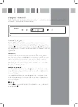
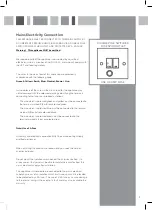
Page 3: ...ctor press and hold the key for 2 seconds The clock display will flash Use or keys to set the hour press key to set after which you can adjust the minutes Once set press key to confirm Adjusting the Fan Speed Once the extractor is turned on press the key to set the fan motor to high speed When pressed again it will reduce the fan speed from high to medium to low and finally off Light Key Press the...

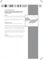
Page 4: ...nd clean the grease filter with hot soapy water at least once a month You can also wash the grease filter in a dishwasher ensuring that you place it in an upright position to prevent damage from other items in the dishwasher After rinsing and drying replace the filter To remove the grease filter push in the button on the handle and then pull down on the filter at the front When you have released i...

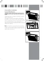
Page 5: ...the use of charcoal filters to remove odours To ensure the best performance from your cooker hood the charcoal filter should be replaced every 3 6 months dependent on use Check with your local retailer or dealer for information on how to obtain replacement charcoal filters Note This charcoal filter is non washable and must be replaced as required To install a new charcoal filter first remove the g...

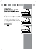
Page 6: ...I Remove the lamp Unplug the lamp wire connector Replace the lamp Fig 4 II Plug the wire connector into the new lamp Place the new lamp into the lamp holder Push the LED lamp into position until it clicks into place Fig 4 III The lights are designed for use during cooking and not for general room illumination Extended use of the lights can reduce their life span Please contact your local retailer ...

Page 7: ...lows The wire which is coloured green and yellow must be connected to the terminal marked E Earth or coloured green The wire which is coloured blue must be connected to the terminal marked N Neutral or coloured black The wire which is coloured brown must be connected to the terminal marked L Live or coloured red Note Use a 3A Fuse Assembly and electrical connection MUST be carried out by suitably ...

Page 8: ...122W All repairs must be carried out by an authorised service engineer 8 ...

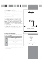
Page 9: ... we recommend the use of a 125mm ducting greater than 700mm then that is the distance that should be observed This is a legal RIDDOR the height The width of any hob must not be greater than the width of the extractor installed above it 9 Fig 5 A B C F E Centre D Gas hob 750mm recommended Electric hob 650mm recommended ...

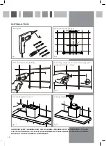
Page 10: ...DAMAGE TO THE INTERNAL WIRING WHICH WILL NOT BE COVERED BY THE WARRANTY 10 10mm Fig 7 Fig 8 Fig 9 Fig 10 Tools required Mark wall as required see Fig 5 Drill 4 holes for mounting the body Fit wall fixings and top screws Ensure that any fixings you use are appropriate for the wall type 8 Fig 11 Secure hood tighten all screws Fig 12 Fit ducting adaptor ...

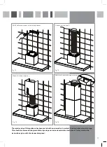
Page 11: ... This should be removed during installation by using a non abrasive stainless steel cleaner Always follow the instructions given with the cleaner being used 11 Fig 14 Fig 15 Fig 16 Fix ducting seal joint Mount the lower chimney Adjust and secure the upper chimney Fig 13 Drill 2 holes and mount the chimney bracket ...

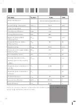
Page 12: ...QMAX 334 9 m3 h Measured electric power at Best WBEP 91 7 W Nominal lighting power WL 2 0 W Average illumination of the lighting system on the cooking surface EMiddle 95 Lux Measured power consumption in standby PS 0 402 W Measured power consumption PO W Sound power level LWA 69 dBA GFEHood 79 7 C LEHood 48 A 12 E O E All instructions dimensions and illustrations are provided for guidance only PRI...

Page 13: ...12 ...

Reviews: