Note:
Unless ordered seperatley the
cylinder is not included in this kit.
Note: If, when fitting the pull handle, the screws make direct contact with the lock-case, please use the shorter (5/8“) screws
included in the fixing pack.
Standard Primera Products are designed for internal applications only. For external applications products plated to “Service
Condition 5” should be used.
1-46-729C
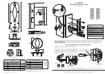
Anti-Ligature Bedroom Lockset
PR6130RBD
Roller Bolt
Dead lock
70
PR⁴-⁵⁸E
Euro Profile
Escutcheon
70
PR7101-TPSP
Thumb Turn
Support Plate
PR4-728-TP
Anti-ligature
Turn/Pull
To adjust Roller Catch projection turn
screw
anti-clockwise to
increase or clockwise
to withdraw
(Max adjustment
6.5mm – 13mm)
Description
Roller Bolt Deadlock 103x235
Spindle Universal 44mm-63mm With O-ring
Turn/Pull complete
729 Pull handle
Escutcheon 58mm Euro
729, 90x282 Radius Back plate
3x25x79mm Turn/Pull support plate
Fixings Included
⁵/⁸”
Machine
Screws
90
PR⁴-⁵⁸E
Euro Profile
Escutcheon
PR⁴-⁷2⁹
Anti-ligature
Pull Handle
PR6130RBD
Roller Bolt Dead lock
PR4-58E
Euro Profile Escutcheon
PR7101-TPSP
Turn/Pull Support Plate
103
80
3
63
72
14
10
60.5
33
35
68
15
58.5
10
25
235
165
30
16
Note:
The cylinder cut out is made on the external side of the door only and must not go right through the door.
79
25
32
58
10
48.50
25°
102
35
3
PR4-728TP
Anti-ligature Turn/Pull
Model Spindle Length Calculation
46
Door Thickness ÷ 2 + 20mm
+3mm
56
Door Thi 11mm
+3mm
66
Door Thickness ÷ 2 + 20mm
+3mm
76
N/A
N/A
86
N/A
N/A
96
N/A
N/A
Note A :
Check exact door thickness of each door
Note B :
Turn/Pull support plate must not be recessed
deeper than the surface of the door.
PR1 Variant
Addition for
Turn/Pull
Repair Plate
46
Door Thickness Less 3mm
56
Door Thickness Less 3mm
66
Door Thickness Less 3mm
76
N/A
86
N/A
96
N/A
If Fitting
Turn/Pull
Repair Plate
Screw Length
= Door
Thickness
Turn/Pull Screw Length
PR4-729A
Anti-ligature Pull Handle
3
32
25
282
175
90
22.5
36
M5 Bolt
from the
other side
of the door
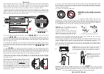
A: This Turn/Pull is equipped with a screw to adjust the projection of the
spindle if required (most likely if the spindle is cut too short in error) see
drawing A
B: When cutting the spindle to the required length, please make sure that
the material is cut from the end marked B as illustrated. The 3 slots at
the opposite end of the spindle C are an important safety feature and
designed to sheer at 50NM to protect the lock and ensure clinical staff
maintain control of the lock at all times. The O-ring in the first slot will
also assist in the retention of the spindle in the nozzle of the Turn/Pull
during normal use.
There must be at least I sheer
point between the end of the
Turn/Pull nozzle & the lockcase.
Important Spindle & Turn/Pull Information
SOP137 Revision (2)
Sheer Points
Do Not Cut Here
O-Ring
Lockcase
Lockcase
Door
A
B
C
Adjust the spindle projection screw
by inserting screwdriver through
the door/lockcase.
The spindle must
engage in the socket
by at least 7mm
Adjust length of spindle by cutting with a
hacksaw at this end. It is important that
the end of the spindle is cut square.
Primer
a Limited, Unit 8 Bankfield House, 250 Bristol
Av
enue, Blackpool, FY2 0JF
t
0330 058 0988
e
sales@safehingeprimera.com
w
www
.safehingeprimera.com
Important Note: products are protected by Intellectual Property Rights including UK and Community Unregistered Design Rights, UK and Community Registered Designs and UK Patents and Patent Applications.
For further details please contact Safehinge Primera Limited.


