Reinforced Locking for Slave Leaf Doors
(PR-6304-RB-RK-LL
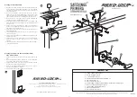
a) 120mm x 30mm Strike Plate x 1
b) 1¼” No 8 Fixing Screws x 4
c) 1” No 6 Fixing Screws x 2
d) Extended Tubular Deadbolt C/W Faceplate x 1
e) 5/8” x No 6 Screw x 4
f) M4 x 16 Machine Screw x 2
g) 70mm x 70mm Escutcheon Plate Assembly (includes Rose & Keyway) x 1
h) 8mm Life-Line Spindle & Grub Screw x 1
i) 70mm x 50mm Reinforcing Plates x 2
j) M4 x 35 Knurled Nut x 4
k) M4 x 30 Machine Screw x 4
Contents List
09|2015
Important Note: Primera products are protected by Intellectual Property Rights including UK and Community Unregistered Design Rights,
UK and Community Registered Designs and UK patents and patent applications.
a
c
k
b
30
120
120
Dim A
3
j
i
9B
9A
10
d
i
e
f
Rhino-Lock
LL
LL
™
Rhino-Lock
™
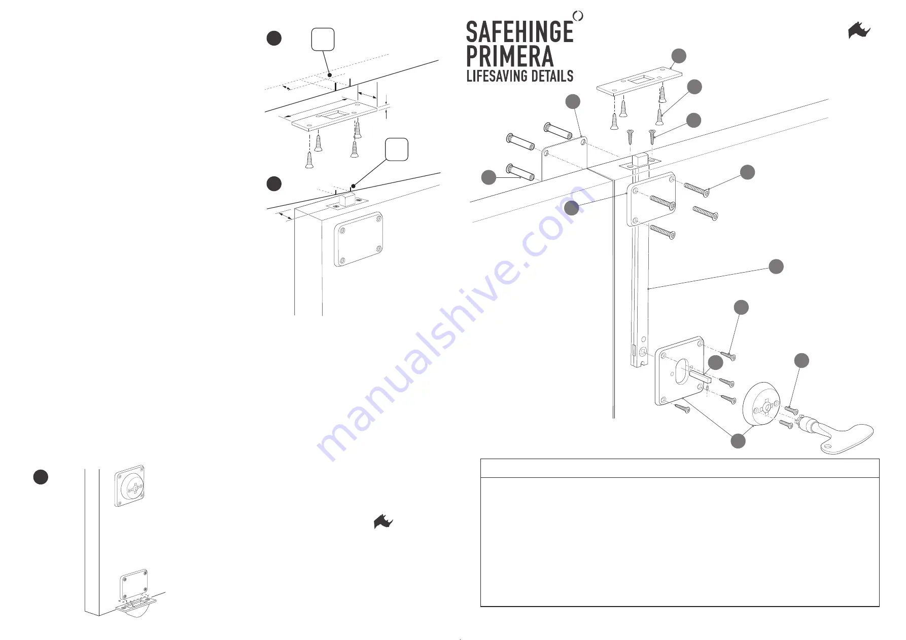
D) Fitting the Flat Strike Plate
1) With the bolt extended, carefully close the door against the frame and
mark a pencil line on either side as illustrated. Then, using a Square
transfer the lines across the rebate to mark the cut out for the bolt as
shown at Diagram 9A.
2) With the bolt withdrawn, close the door and inspect the door
alignment in the frame from the inside taking note of any gap or twist.
Then with the door open and bolt extended, measure from the back
edge of the door to the back of the bolt as shown at dimension ‘A’
3) Mark dimension ‘A’ in the frame rebate as shown at Diagram 9B
allowing for any gap or twist identified at point 2.
4) Using the markings as a guide, squarely align the strike plate in the
frame rebate and draw a pencil line around the rectangular hole for
the bolt cut out.
5) Using a 13mm flat bit, drill a hole 17mm deep to remove the bulk of
the timber cut out. Afterwards, chisel the residual timber in the corners
away leaving a neat rectangular hole.
6) Close the door and throw the bolt to check the alignment is correct
before fitting the strike.
7) Carefully align the strike plate over the bolt cut out and mark a pencil
line around the plate.
8) Using a chisel, let the strike in to the rebate so that it sits flush with the
surface of the timber.
9) Using a 2mm bit, drill four pilot holes for the strike plate fixings and
secure the strike into position using the 4 x 1 ¼” No 8 screws
supplied.
10) The above technique can be used as a general guide when fitting a
strike plate to timber floor.
E) Fitting the Easy Clean Socket (Optional Extra)
P/No. PR-6610-ECS
1) Using a pencil mark the position for the Easy Clean Socket on the
floor.
2) Mark a rectangle 20mm x 45mm to identify the concrete that needs to
be removed to allow the socket to sit in the floor.
3) Using masonary bit and cold chisel, remove the concrete to enable
the Easy Clean Socket to fit flat on the floor.
4) Mark the two fixing positions and drill two 7mm dia holes to
accommodate the rawlplugs supplied.
5) Secure Socket to floor using anti-tamper screws supplied.
h
Dim A
All rights reserved © 2013 Primera Ltd
g
For further details please contact
Primer
a Limited, Unit 8 Bankfield House, 250 Bristol
Av
enue, Blackpool, FY2 0JF
t
0330 058 0988
f
01253 508652
e
info@safehingeprimera.com
w
www
.safehinge.com
SOP093 Revision (1)


