Primex Wireless, Inc.
Manual Part No.: Q12354-INST 040512
1
XR Electric Analog Clock
This instruction sheet provides the installation instructions for XR Electric Analog Clock models. It is recommended to
read the Analog Clock User Guide for detailed safety precautions, and installation and maintenance procedures.
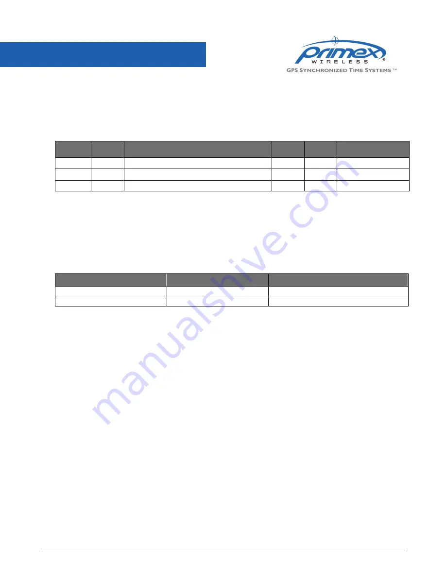
Electric Model Power Specifications
Model
Current
Draw
Cord Specifications
Line
Neutral
Ground (Earth)
24 VAC*
21mA
18” (45.72cm) pigtail/hardwired
Yellow
Yellow
120 VAC*
25mA
18” (45.72cm) standard non-polarized two-prong plug
Black
White
Green
240 VAC** 67mA
18” (45.72cm) BSI 1363 plug
Brown
Blue
Green with yellow stripe
* Available in US/Canada only
** Available in UK only
Installation Requirements
Before installing an analog clock, verify your system’s transmitter is operating properly and sending a signal with
adequate building coverage (refer to the manual accompanying the transmitter). Clocks are required to be installed at a
location within adequate transmission range of the transmitter.
The backs of most analog clocks feature two specially designed Clock-Lock hangers spaced at precise distances, one
on the top, and the other on the bottom. The hole spacing dimensions are listed below.
Clock Size
Hole Spacing
Clock-Lock Feature
12.5” (31.75cm)
9” (22.86cm)
Yes
16” (40.64cm)
9” (22.86cm)
Yes
Installation Procedures
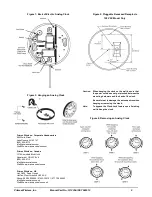
Pluggable Surface Receptacle (Figure 1)
The power cord is wrapped around the two posts on the back of the clock and can be unwrapped or wrapped to the
desired length. The power cord is to be routed through the strain relief and exit the bottom of the clock through the exit
slot away from the upper portion of the clock’s antenna to maintain optimal reception. The excess cord can be wound
around the two cord posts.
Pluggable Recessed Receptacle Optional Installation 120 VAC Model Only (Figure 2)
The receptacle may be behind the clock (with excess cord wound around the two cord posts). To assure that the cord
does not prevent the clock from resting flush against the wall, the center of the recessed receptacle should be located
about 2.5” (6.35cm) to the right of the clock’s center.
Pigtail/Hardwired Configuration Only
Please be sure to leave a minimum of 6” (15.24cm) of cord inside the junction box. To conform to UL and National
Building Code, the use of the Clock-Lock feature is required for this configuration.
Self Initialization
After the power supply is applied, the clock’s receiver automatically begins to step through all channels rapidly, normally
taking 1 second to 20 seconds, scanning for a valid time signal from the transmitter. When the time displayed matches
the time displayed on the transmitter, the clock is ready for normal operation.
Installation Instructions