background image

WARNINGS

System Design

Do not create GP touch panel switches that could possibly endanger the safety of equipment
and personnel. Damage to the GP, its I/O unit(s), cable(s), and other related equipment can
cause an output signal to remain continuously ON or OFF and possibly cause a major acci-
dent. Therefore, design all monitoring circuits using limit switches, etc. to detect incorrect
device movement. To prevent accidents related to incorrect signal output or operation, design
all switches used to control vital machine operations so they are operated via a separate
control system.

Do not create switches used to control machine safety operations, such as an emergency stop
switch, as a GP touch screen icon. Be sure to install these switches as separate hardware
switches, otherwise severe bodily injury or equipment damage can occur.

Please design your system so that equipment will not malfunction due to a communication
fault between the GP and its host controller. This is to prevent any possibility of bodily injury
or material damage.

Do not use the GP unit as a warning device for critical alarms that can cause serious operator
injury, machine damage or production stoppage. Critical alarm indicators and their control/
activator units must be designed using stand-alone hardware and/or mechanical interlocks.

The GP is not appropriate for use with aircraft control devices, aerospace equipment, central
trunk data transmission (communication) devices, nuclear power control devices, or medical
life support equipment, due to these devices’ inherent requirements of extremely high levels
of safety and reliability.

When using the GP with transportation vehicles (trains, cars and ships), disaster and crime
prevention devices, various types of safety equipment, non-life support related medical
devices, etc. redundant and/or failsafe system designs should be used to ensure the proper
degree of reliability and safety.

After the GP’s backlight burns out, unlike the GP’s “Standby Mode”, the touch panel is still
active. If the operator fails to notice that the backlight is burned out and touches the panel, a
potentially dangerous machine miss-operation can occur. Therefore, do not use GP touch
switches for the control of any equipment safety mechanisms, such as Emergency Stop
switches, etc. that protect humans and equipment from injury and damage. If your GP's
backlight suddenly turns OFF, use the following steps to determine if the backlight is actu-
ally burned out.
1) If your GP is not set to "Standby Mode" and the screen has gone blank, your backlight is

burned out.

2) Or, if your GP is set to "Standby Mode", but touching the screen does not cause the

display to reappear, your backlight is burned out.

Also, to prevent accidental machine miss-operation, Digital suggests you use the GP’s built-
in

 “USE TOUCH PANEL AFTER BACKLIGHT BURNOUT” 

feature, that will automati-

cally detect a burnout and disable the touch screen.

Installation

High voltage runs through the GP. Except for replacing the backlight, never disassemble the
GP, otherwise an electric shock can occur.

Do not modify the GP unit.  Doing so may cause a fire or an electric shock.

Do not use the GP in an environment where flammable gasses are present, since operating
the GP may cause an explosion.
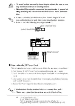
Wiring

To prevent an electric shock, be sure to confirm that the GP's power cord is not connected to
the main power when connecting any cords, cables or lines to the GP.

Be sure to replace the GP's plastic terminal block cover after wiring is completed, since
operating the GP without the cover may lead to an electric shock

Do not use power beyond the GP's specified voltage range. Doing so may cause a fire or an
electric shock.

Maintenance

The GP uses a lithium battery for backing up its internal clock data.  If the battery is incor-
rectly replaced, the battery may explode.  To prevent this, please do not replace the battery
yourself.  When the battery needs to be replaced, please contact your local GP distributor.

Essential Safety Precautions

Summary of Contents for GP2500-TC11

Page 1: ...iability and safety After the GP s backlight burns out unlike the GP s Standby Mode the touch panel is still active If the operator fails to notice that the backlight is burned out and touches the panel a potentially dangerous machine miss operation can occur Therefore do not use GP touch switches for the control of any equipment safety mechanisms such as Emergency Stop switches etc that protect h...

Page 2: ...ith a hard or pointed object or press on the touch panel with too much force since it may damage the touch panel or the display Do not install the GP where the ambient temperature can exceed the allowed range Doing so may cause the GP to malfunction or shorten its operation life Do not restrict or limit the GP s naturally occurring rear face ventilation or storing or using the GP in an environment...

Page 3: ...her than that allowed by UL stan dard requirements Make sure to set up a switch to turn off the power to the GP in an accessible position on the end use product that the GP unit is built in Make sure to consider the current and voltage when selecting the switch Make sure that the frame of the product to which the GP unit is built in con forms to UL60950 standard requirements UL1604 Conditions of A...

Page 4: ...rnal components may become higher than that allowed by the stan dard requirements Make sure to set up a switch to turn off the power to the GP in an accessible position on the end use product that the GP unit is built in Make sure to consider the current and voltage when selecting the switch Make sure that the frame of the product to which the GP unit is built in con forms to EN60950 standard requ...

Page 5: ... packed with special attention to quality However should you find anything damaged or missing please contact your local GP distributor im mediately Package Contents GP Unit 1 GP2500 TC11 GP2600 TC11 Installation Guide 1 This Guide Installation Gasket 1 attached to the GP unit Installation Fasteners 4 set Screw Lock Terminal Block 1 attached to the GP unit ...

Page 6: ... Unit Interface 2 G CF Card Expansion Interface H CF Card Cover I CF Card Access Lamp J CF Card Slot K Serial Interface HOST I F 25 pin L Serial Interface SUB SIO 9 pin M Printer Interface Half Pitch 20 pin N Ethernet Interface 10BASE T O Screw Lock Terminal Block 12 pin P Tool Connector Connects a Data Transfer Cable or bar code reader LED GP Status Not Lit Power is OFF Green Normal operation Ora...

Page 7: ...ion ON OFF Note 1 This Dip switch setting controls the startup from a CF Card Startup from CF Card is enabled Startup from CF Card is disabled CF Card with startup data required 2 Reserved 3 Reserved 4 This setting controls the forced closing ofthe CF Card cover Forced close enabled Forced close disabled Used when CF Card cover is damaged Keep these switches OFF ...

Page 8: ...g XM2A 2501 made by OMRON Corp Recommended Cover Dsub 25 pin Cover XM2S 2511 made by OMRON Corp Jack Screw XM2Z 0071 made by OMRON Corp Recommended Cable CO MA VV SB5P x 28AWG made by HITACHI Cable Ltd This GP unit s serial port is not isolated When the host PLC unit is also not isolated and to reduce the risk of damaging the RS 422 circuit be sure to connect the 7 SG Signal Ground terminal Pin 14...

Page 9: ...422 For RS 232C Connectors Do not connect 9 TRMX 10 RDA 11 SDA 15 SDB 16 RDB 18 CSB 19 ERB 21 CSA and 22 ERA The 1 FG terminal should only be connected if it is required by the device being connected to Serial Interface SUB SIO Connect a Serial Bar code reader or a 2 Dimensional code reader to this interface Printer Interface Half Pitch 20 pin When connecting a printer use Digital s printer cable ...

Page 10: ... the straight sections of the groove Inserting it into a corner may lead to its eventually tearing A gasket which has been used for a long period of time may have scratches or dirt on it and could have lost much of its dust and drip resistance Be sure to change the gasket periodically or when scratches or dirt become visible Confirm the Installation Gasket s Positioning It is strongly recommended ...

Page 11: ...ner Create a Panel Cut and insert the GP into the panel from the front Attach the Installation Fasteners from Inside the Panel The following figures show the four 4 fastener insertion slot locations Insert each fastener s hook into the slot and tighten it with a screwdriver Panel GP Tightening the screws with too much force can damage the GP s plastic case The necessary torque is 0 5 N m Depending...

Page 12: ...P Power Cord When connecting the power cord be sure to follow the procedures given below 1 Confirm that the GP s Power Cord is unplugged from the power supply 2 Use a screwdriver to remove the Power Input Terminal Block s clear plastic cover 3 Unscrew the screws from the middle three 3 terminals align the Ring Terminals and re attach the screws 4 Replace the Power Input Terminal Block s clear plas...

Page 13: ...ial attention to the following instructions when connecting the power cord terminals to the GP unit If the power supply voltage exceeds the GP s specified range connect a voltage transformer Between the line and the ground be sure to use a low noise power supply If there is still an excessive amount of noise connect a noise reducing transformer Input and Output signal lines must be separated from ...

Reviews: