background image

CAUTION

Read all precautions and instruc-
tions in this manual before using
this equipment. Save this manual
for future reference.

Arm Lower

Upper  Ab

Leg

Weight

Press

Pulley Pulley

Pulley

Lever

Plates

(lbs.)

(lbs.)

(lbs.)

(lbs.)

(lbs.)

Top

24

17

13

11

17

1

36

25

26

22

25

2

45

37

39

33

37

3

55

48

49

45

48

4

67

58

61

58

58

5

87

77

81

73

77

6

93

89

91

82

89

7

105

96

99

92

96

8

114

103

107

104

103

9

130

114

123

113

114

10

137

126

138

125

126

11

151

137

150

139

137

12

157

149

165

143

149

13

179

162

179

163

162

14

186

175

182

175

175

USER’S MANUAL

Model No. PFEMSY75001
Serial No. 

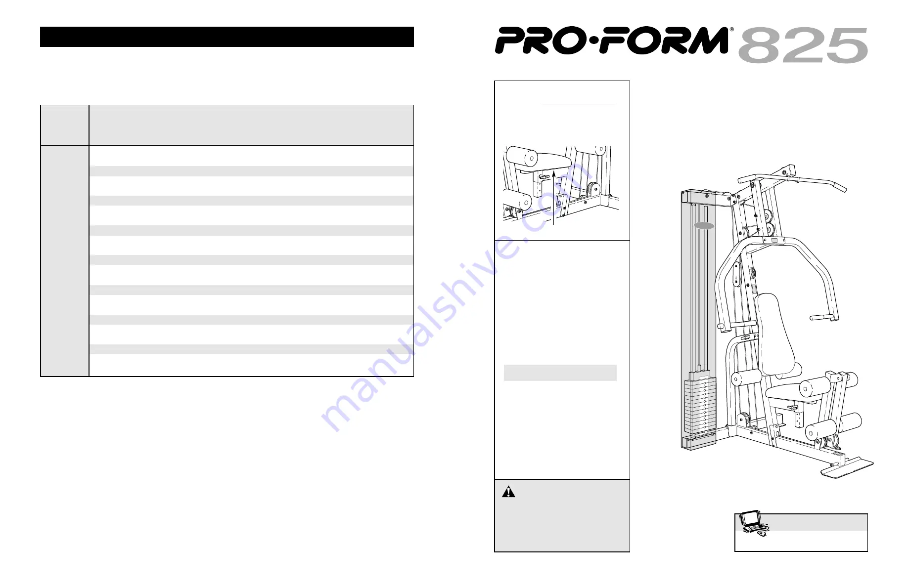
The serial number is found in the
location shown below. Write the
serial number in the space above.

QUESTIONS?

As a manufacturer, we are 
committed to providing 
complete customer satisfaction.
If you have questions, or if 
there are missing parts, we will
guarantee complete satisfaction
through our Customer Service
Department.

Please CALL:

0345-089009

Or WRITE:
ICON Health & Fitness Ltd.
Unit 4
Revie Road Industrial Estate
Revie Road
Leeds
LS11 8JG

Part No. 171789 R0301A

Printed in Canada © 2001 ICON Health & Fitness, Inc.

Serial Number Decal

Weight Resistance Chart

www.proform.com

Visit our website at

This chart shows the approximate weight resistance at each exercise station. “Top” refers to the 10-pound top
weight; the other numbers refer to the 10-pound weight plates. Note: The actual resistance at each weight
station may vary due to differences in individual weight plates, as well as friction between the cables,
pulleys, and weight guides.

Summary of Contents for Stride Select 825

Page 1: ...he space above QUESTIONS As a manufacturer we are committed to providing complete customer satisfaction If you have questions or if there are missing parts we will guarantee complete satisfaction thro...

Page 2: ...he other adjustment holes in the Pulley Plates To do this remove the 3 8 x 1 3 4 Bolt 60 the Cable Trap 44 and the 3 8 Nylon Jamnut 63 Move the Pulley and re attach it with the Bolt Cable Trap and Loc...

Page 3: ...for home use only Do not use the training system in a commercial rental or institutional setting 4 If you feel pain or dizziness at any time while exercising stop immediately and begin cool ing down...

Page 4: ...at the end of the Weight Pin is touching the Weights The setting of the weight stack can be changed from 10 pounds to 150 pounds in incre ments of 10 pounds Note Due to the cables and pul leys the am...

Page 5: ...BLY REQUIRES TWO PERSONS For your convenience and safety assemble the training system with the help of another person SET ASIDE ENOUGH TIME Due to the many features of the training system the assembly...

Page 6: ...through the bracket and the Main Upright 3 from the side Hand tighten two 5 16 Nylon Locknuts 21 onto the Bolts Do not tighten the Nylon Locknuts yet 65 50 55 78 33 29 33 8 Front Leg 3 21 29 Make sur...

Page 7: ...iser 5 Attach the indicated Weight Guide 23 to the Stabiliser 5 with a 3 8 x 2 1 2 Bolt 54 two 3 8 Flat Washers 55 two Pulley Bushings 42 and a 3 8 Nylon Jamnut 63 5 23 19 55 5 23 19 Hole 63 55 42 42...

Page 8: ...hed Weight Tube 36 onto the Weight Guides 23 The Weight Tube will slide into the hole in the centre of the Weights 26 Place the Top Frame 1 over the Weight Guides 23 so the Weight Guides fit into the...

Page 9: ...he end of the High Cable is the primary means for tighten ing both Cables Thread the bolt into the Weight Tube until both Cables are tight and rest firmly in the grooves of all pulleys When both Cable...

Page 10: ...h Cable 73 around a 4 Pulley 35 Attach the Pulley inside the Main Upright 3 with a 3 8 x 2 1 2 Bolt 54 two 3 8 Flat Washers 55 two Pulley Bushings 42 and a 3 8 Nylon Jamnut 63 11 55 42 63 3 35 42 55 5...

Page 11: ...s below each part refers to the key number of the part Important Some parts may have been pre assembled for shipping purposes If you cannot find a part in the parts bags check to see if it has been pr...

Page 12: ...2 Bolzen 62 3 8 x 2 1 2 Bolzen 54 3 8 x 3 Bolzen 45 3 8 x 4 Bolzen 65 3 8 flachen Unterlegscheibe 55 Rollenbuchse 42 5 16 flachen Unterlegscheibe 80 5 16 Nylon Kontermutter 79 8 x 3 4 Schraube 32 3 8...

Page 13: ...aded Clip 39 1 Weight Pin 40 1 1 1 2 Flat Washer 41 1 Backrest 42 21 5 8 x 1 2 Pulley Bushing 43 2 1 x 2 Inner Cap 44 3 Cable Trap 45 4 3 8 x 3 Bolt 46 1 Press Arm 47 2 1 2 x 1 8 Flange Bushing 48 1 1...

Page 14: ...68 40 76 26 39 49 2 16 51 64 66 51 63 55 42 54 55 42 35 42 42 35 42 42 63 60 31 35 31 35 44 44 35 42 42 63 63 54 60 50 1 55 55 42 35 42 42 35 42 55 35 42 42 35 14 73 42 42 55 14 43 43 28 30 34 34 30 5...

Reviews: