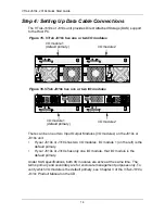
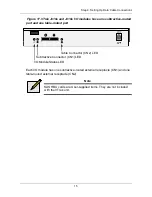
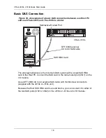
background image


VT

RAK


J610s, J310s

Q

UICK

 S

TART

 G

UIDE

Version 1.0

© 2007 Promise Technology, Inc. All Rights Reserved.

Summary of Contents for VTrak J310S

Page 1: ...VTRAK J610s J310s QUICK START GUIDE Version 1 0 2007 Promise Technology Inc All Rights Reserved ...

Page 2: ...J610s or J310s Unit Quick Start Guide Front bezel and key RJ11 to DB9 serial data cable Units with one I O module 1 Units with two I O modules 2 1 0m 3 3 ft SAS cable Units with one I O module 1 Units with two I O modules 2 Screws for disk drives J610s 70 including 6 spares J310s 50 including 2 spares Left and right mounting rails Left and right center mount brackets 1 5m 4 9 ft Power cords 2 CD w...

Page 3: ...ak J610s rear view Figure 3 VTrak J310s front view with bezel removed Drive Carrier LEDs Drive Carriers Power and Status LEDs 115200 8 N 1 115200 8 N 1 Cooling Unit 1 Power Supply 1 Power Supply 2 Cooling Unit 2 I O module 2 I O module 1 Drive Carrier LEDs Drive Carriers Power and Status LEDs ...

Page 4: ...10s rear view Some J610s and J310s units ship with a single I O module and a dummy module installed in the place of the second I O module O I O I 115200 8 N 1 115200 8 N 1 Cooling Unit 1 Power Supply 1 Power Supply 2 I O module 2 Cooling Unit 2 I O module 1 ...

Page 5: ...eeded Cautions At least two persons are required to safely lift place and attach the VTrak subsystem into a rack system Do not lift or move the VTrak subsystem by the handles power supplies or the controller units Hold the subsystem itself Do not install the VTrak subsystem into a rack without rails to support the subsystem Only a qualified electrician who is familiar with the installation procedu...

Page 6: ...Tighten the adjustment screws and the attaching screws 6 Place the VTrak subsystem onto the rails 7 Secure the VTrak subsystem to the rack through each handle using the attaching screws from your rack system Figure 6 Rack mount assembly diagram Inside of post Rack front post Rail attaching screw not included Rail adjustment screw Flange Rail attaching screw not included Inside of post Rack back po...

Page 7: ... plate with six screws included See Figure 8 4 Slide one of the rails over the plate on one side of the enclosure Cautions At least two persons are required to safely lift place and attach the VTrak subsystem into a rack system Do not lift or move the VTrak subsystem by the handles power supplies or the controller units Hold the subsystem itself Do not install the VTrak subsystem into a rack witho...

Page 8: ...the subsystem with mounting rails into your rack system 8 Attach the mounting rail assemblies to the outside of the rack posts using the attaching screws from your rack system 9 Square the rail assemblies in the rack 10 Tighten the adjustment screws and the attaching screws 11 Place the VTrak subsystem onto the rails 12 Secure the VTrak subsystem to the rack through each handle using the attaching...

Page 9: ... in a Rack 9 Figure 9 Mounting rail installation Inside of post Rack front post Rail attaching screw not included Rail adjustment screw Mounting Rail Rail attaching screw not included Inside of post Rack back post Sliding plate ...

Page 10: ...s so that both modules can access a SATA disk drive Place the optional AAMUX into the disk drive carrier and attach it with the four screws Install only the screws supplied with the AAMUX The AAMUX fits into the carrier with the SAS connector at the back See Figure 6 on page 12 Snug each screw Be careful not to over tighten 4 Carefully lay the drive into the drive carrier at the front so that the ...

Page 11: ...gh the holes in the drive carrier and into the bottom of the disk drive see Figure 5 Install only the screws supplied with the VTrak Install four screws per drive Snug each screw Be careful not to over tighten 6 Reinstall the drive carrier into the VTrak chassis 7 Repeat steps 2 through 5 until all of your disk drives are installed 8 Replace the front bezel Figure 11 Drive carrier with SAS disk dr...

Page 12: ...iers into the enclosure to ensure proper airflow for cooling A VTrak J610s or J310s carrier is similar in appearance but is NOT interchangeable with a VTrak M500f i p drive carrier Important Be sure each drive is securely fastened to its carrier Proper installation ensures adequate grounding and minimizes vibration Do not install drives with fewer than four screws SATA Disk Drive AAMUX adapter SAS...

Page 13: ...o the Port number used for management For more information see Chapter 3 of the VTrak J610s J310s Product Manual on the CD Numbers are stamped above each drive bay for easy indentification Figure 13 VTrak J610s drive slot numbering Figure 14 VTrak J310s drive slot numbering 8 6 5 1 2 3 4 7 13 14 15 16 9 10 11 12 8 6 5 1 2 3 4 7 9 10 11 12 ...

Page 14: ... or J310s has two I O modules I O module 1 on the left is the default primary If your J610s or J310s has only one I O module that I O module is the default primary Under SAS specifications both I O modules are active at the same time The terms primary and secondary are for enclosure management purposes only To verify which I O module is the default primary see Chapter 3 of the VTrak J610s J310s Pr...

Page 15: ... port and one table routed port Each I O module has one subtractive routed external receptacle CN1 and one table routed external receptacle CN2 Note SAS HBA cards are User supplied items They are not included with the VTrak unit 115200 8 N 1 Subtractive Connector CN1 LED Table Connector CN2 LED I O Module Status LED ...

Page 16: ... Host PC Connect the SAS card to the table routed port CN1 on the I O module Use a SFF 8088 4X to 4X external SAS cable with thumbscrew connectors supplied with the J610s or J310s unit Because the Host SAS HBA card is an end device you can connect it to either of the two SAS ports CN1 or CN2 on the J610s or J310s unit s I O module O I O I 115200 8 N 1 115200 8 N 1 PC SAS HBA Card VTrak J310s Subtr...

Page 17: ...able supplied with the J610s or J310s unit Connect the I O module s table routed port CN2 on the first J610s or J310s unit to the subtractive routed port CN1 on the next J610s or J310s unit You can cascade up to four J610s or J310s units in this manner You can mix J610s and J310s units in the same cascade Figure 19 An example of a cascaded DAS connection between one Host PC and three VTrak J310s u...

Page 18: ...le of a redundant DAS connection between two Host PCs and four cascaded VTrak J310s units The J610s is similar O I O I 115200 8 N 1 115200 8 N 1 O I O I 115200 8 N 1 115200 8 N 1 O I O I 115200 8 N 1 115200 8 N 1 O I O I 115200 8 N 1 115200 8 N 1 PC SAS HBA Cards VTrak J310s PC VTrak J310s VTrak J310s VTrak J310s CN2 CN1 CN1 CN1 CN1 CN2 CN2 ...

Page 19: ...ect the SAS HBA card in the second Host PC to the subtractive routed port CN2 on the other I O module of the first J610s or J310s unit Connect the table routed ports CN2 on the I O modules of the first J610s or J310s unit to the subtractive routed ports CN1 on the I O modules of the next J610s or J310s unit Connect the remaining J610s or J310s units in the same manner You can mix J610s and J310s u...

Page 20: ...e VTrak to the RJ11 serial connector on one of the I O modules 2 Attach a null modem cable to the DB9 end of the RJ11 to DB9 serial data cable 3 Attach the other end of the null modem cable to a serial port on the Host PC or Server If your PC has two DB9 COM ports and your J610s or J310s unit has two I O modules you can connect a second null modem cable and RJ11 to DB9 serial data cable the I O mo...

Page 21: ...ice every 3 seconds if two I O modules are installed Power and FRU LEDs display green continuously I O module LEDs flash green if there is activity on that connection There are two LEDs on each Drive Carrier They report the presence of power and a disk drive and the current condition of the drive Figure 23 VTrak J610s J310s disk carrier LEDs Within one minute the Power Activity should display Gree...

Page 22: ... screen indicates that you have a connection and the CLI is ready to accept commands CLI Command Set The CLI has the following set of commands cable Specifies the length of cable for optimal signal quality enclosure Displays full information on the J310s or J610s unit and all its components expander addresses and SAS addresses help Use alone or with a command such as help enclosure enclosure help ...

Page 23: ...o the default primary I O module If the Role is StandBy you are connected to the default secondary What happens if a disk drive fails Depending on the nature of the failure the failed drive the drive might not appear in the CLI or the failed drive might appear with an error when you run the enclosure command or the link command See the VTrak J610s J310s Product Manual on the CD for more informatio...

Page 24: ...U type hard drive model s SAS SATA ATA ATAPI drives devices and other controllers Technical Support Services United States Important Promise offers 24x7 live technical support in English only for registered owners of VTrak products To register point your browser to http www promise com support warranty warranty_eng_pdchoose asp Promise Online Web Site Promise Online eSupport http www promise com s...

Page 25: ...port support de promise emea com Fax Technical Support 49 0 2 31 56 76 48 29 Attn Technical Support Phone Technical Support 49 0 2 31 56 76 48 10 8 30am 5 00pm M F Germany Time If you wish to write us for support Promise Technology Germany Attn Technical Support Europaplatz 9 44269 Dortmund Germany E mail Support support it promise emea com Fax Technical Support 0039 06 367 12400 Attn Technical Su...

Page 26: ...y Inc Attn Technical Support 2F No 30 Industry E Rd IX Science based Industrial Park Hsin Chu 30075 Taiwan R O C E mail Support support china promise com Fax Technical Support 86 10 8857 8015 Attn Technical Support Phone Technical Support 86 10 8857 8085 8095 If you wish to write us for support Promise Technology China Attn Technical Support Room 1205 Tower C Webok Time Center No 17 South Zhong Gu...

Reviews: