background image

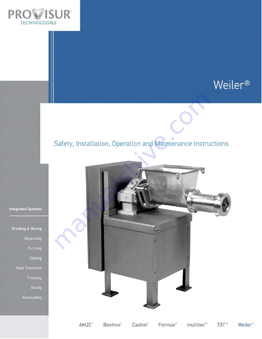
Model 6 Grinder

AAM

136

  Revised June 5, 2012

1

Next Generation of Grinding Technology

Grinding

Summary of Contents for Weiler 6

Page 1: ...Model 6 Grinder AAM 136 Revised June 5 2012 1 Next Generation of Grinding Technology Grinding ...

Page 2: ...ING PIN Fig 20 14 STEP 7 INSTALL KNIFEHOLDER Fig 21 14 STEP 8 INSTALL PLATE AND OPTIONAL BCA ONLY BUSHING Fig 22 15 STEP 9 Optional INSTALLATION OF TEARDROP HOLE PLATES Fig 23 15 STEP 10 INSTALL GRINDER RING Fig 24 15 STEP 11 INSTALL ORIFICE PLATE GUARD Fig 25 16 OPERATING INSTRUCTIONS 17 HOPPER COVER SAFETY INTERLOCK SWITCH OPTIONAL Fig 26 17 HOPPER GUARD Fig 27 17 PRE OPERATION CHECKS 17 RECOMME...

Page 3: ... 4 Do not install any walkways or service platforms which would allow any persons to reach dangerous nip points while the machine is operating 5 Remove foreign objects or product from the hopper with long handled tools Use long handled brushes or mops if brushing or wiping is necessary 6 If foreign objects metal hooks shovels forks knives boxes paper etc accidentally fall into the hopper do not at...

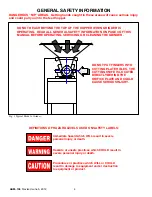
Page 4: ...NG SERVICING OR CLEANING THE GRINDER DO NOT PUT FINGERS INTO CUTTING PLATE HOLES THE CUTTING KNIFE IS LOCATED DIRECTLY BEHIND THE ORIFICE PLATE AND COULD CAUSE SERIOUS INJURY Fig 1 Typical Model 6 Grinder DEFINITIONS OF HAZARD LEVELS USED ON SAFETY LABELS Immediate hazard which WILL result in severe personal injury or death Hazards or unsafe practices which COULD result in severe personal injury o...

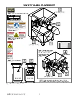
Page 5: ...iler Serial Number Tag and opposite side and opposite side and opposite side and opposite side NOTE Right Hand Side Mount frame shown For Left Hand Side Mount frames label placement should be in the same general location Label 3 018 3505 Read and Understand Manual Label 5 018 0612 Rotating Parts Inside Required Number Label 1 1 each Label 2 1 each Label 3 3 each Label 4 2 each Label 5 2 each REAR ...

Page 6: ...feed hopper head assembly The feed hopper head assembly is supported on a single reduction gearbox The feed screw is driven by the main shaft of the gearbox and transports the product through a fluted head and through sizing holes in a plate GRINDER APPLICATIONS Each Weilerr grinder is designed to grind a specific product or products If the grinder will be used for work other than originally inten...

Page 7: ... on frame and feed hopper b Spare Parts should be accounted for See Spare Parts c All exposed fasteners should be tight and accounted for INTERIOR CHECK Check the following a Are motor and gearbox pulleys aligned and tight b Remove guard cover and check drive belt chain alignment and tension c Check oil level in gearboxes Refer to Lubrication Instructions in the Gearbox Service Instructions d Gene...

Page 8: ...valent shall apply to all electrical installations and utilization equipment WARNING To prevent hazardous situations for each machine 1 Do NOT use dual controls more than one ON OFF switch for the same motor 2 Do NOT use dual circuits more than one power source to the same motor 3 Do NOT use the grinder starter controls to supply power for any other machines 4 The operators control station shall n...

Page 9: ...Lifts end of feed screw to center the plate in head opening Used to remove and install plate bushing assembly Also used to remove tension spring from feed screw pin hole KNIFE INSERT REMOVAL TOOL Use this tool to remove inserts when they become worn down Refer to Page 29 STEP 1 REMOVE ORIFICE PLATE GUARD Fig 8 Loosen thumb screws and remove orifice plate guard Set aside for cleaning later ORIFICE ...

Page 10: ...Centering Pin Removal STEP 6 REMOVE SPRING Fig 13 SPRING Fig 13 Spring Removal STEP 7 REMOVE FEED SCREW WARNING Use caution when handling Feed Screws can weigh 100 lbs 45 KG or more STEP 8 FEED SCREW SUPPORT CART Fig 14 After feed screw is removed from grinder place it on a stable support for cleaning Remove excluder seal from drive end EXCLUDER SEAL FEED SCREW SUPPORT CART Fig 14 Typical Feed Scr...

Page 11: ...ION AND INSTRUCTION OF CLEANING STAFF Always make sure that the machine is cleaned by a qualified and well instructed staff which has read and understood this chapter 3 FREQUENCY The machine is to be cleaned daily according to demand and to existing requirements of the authorities 4 PROCEDURE a Thoroughly pre flush the overall unit with steam and or high pressure water of at least 122 140 F 50 60 ...

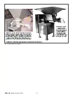
Page 12: ...E OF UNIT AS DESCRIBED ABOVE FRAME SIDE PANELS SHOULD BE REMOVED PERIODICALLY WEEKLY FOR CLEANING AS NECESSARY REMOVE PLATE GUARD AND CUTTING PARTS AS DESCRIBED IN DISASSEMBLY INSTRUCTIONS THOROUGHLY CLEAN INSIDE AND OUTSIDE OF UNIT Adhere to chemical manufacturers instructions at all times Fig 15 Typical Model 6 Grinder ...

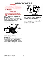
Page 13: ...EAD PRESSURE FLIGHT ÉÉÉ ÉÉÉ ÉÉÉ ÉÉÉ ÉÉÉÉÉ ÉÉÉÉÉ ÇÇÇÇÇÇ ÇÇÇÇÇÇ ÇÇÇÇÇÇ ÇÇÇÇÇÇ 15 8mm Fig 16 Check Feed Screw Head Space STEP 3 ADJUST FEED SCREW HEAD SPACE Fig 17 Make certain that the thrust screw or cap screw on the back of the feed screw or on the gearbox mainshaft is securely tightened and is in good condition Adding a washer will decrease the feed screw head space Removing a washer will increas...

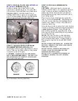
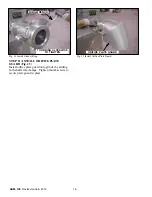
Page 14: ...NG PIN Fig 20 Lubricate pin with a small amount of U S D A approved or equivalent grease or mineral oil and insert over spring NOTE Pin shoulder should project 3 16 from feed screw recess CENTERING PIN Fig 20 Install Centering Pin STEP 7 INSTALL KNIFEHOLDER Fig 21 Install knifeholder If two blade knifeholder is used line up the blades with pressure flights Failure to install two blade knifeholders...

Page 15: ...nd lubricated with U S D A or equivalent approved grease or mineral oil before installing ring onto grinder head Dirty threads will cause incorrect plate knifeholder spring tension and will result in poor cutting action Place ring onto head Hold pressure against the ring as you turn CLOCKWISE If threading does not occur reverse direction still holding pressure until the ring jumps a thread Then th...

Page 16: ...ING WRENCH Fig 24 Install Grinder Ring STEP 11 INSTALL ORIFICE PLATE GUARD Fig 25 Install orifice plate guard onto grinder by sliding both shafts into clamps Tighten thumb screws to secure plate guard in place ORIFICE PLATE GUARD Fig 25 Install Orifice Plate Guard ...

Page 17: ... HOPPER COVER SAFETY INTERLOCK SWITCH Fig 26 Hopper Cover Safety Switch HOPPER GUARD Fig 27 If your unit is not equipped with a hopper cover then it may have a hopper guard with rods To remove the hopper guard during cleaning or maintenance you must remove the hair pin clips from the ends of the rod and slide the rod out Tilt the hopper guard up to allow access to the inside of the hopper for clea...

Page 18: ...d hopper with forks or rakes while the grinder is in operation STOP THE GRINDER and LOCK OUT MAIN POWER WITH A PADLOCK BEFORE ATTEMPTING TO CLEAR THE HOPPER If manual feeding is necessary for purposes of inspection or other reasons the product should be gathered on a feed table Use a fork or rake to feed the product into the hopper at a steady rate and from a safe distance Make sure all appropriat...

Page 19: ...ts begin to squeal or when other maintenance must be performed to resolve a problem LOCK OUT WITH A PADLOCK Fig 32 Shut Off and Lock Out Power with a Padlock WARNING In all cases after stopping the grinder shut off and lock out main power with a padlock before trying to resolve the problem NORMAL SHUT DOWN a For Thawed Tempered Meats and Other Soft Products The grinder can be stopped at any time p...

Page 20: ...te bushing Knifeholder Centering pin Knife tension spring Feed screw Excluder seal WEEKLY or EVERY 40 HOURS CHECK And tighten head bolts INSPECT Head and ring threads EVERY 3 MONTHS or 1000 HOURS CHECK Drive belt tension pulleys and alignment INSPECT Drive spline on gearbox shaft and feed screw INSPECT Condition of head flutes and outside diameter INSPECT Motors for excessive dirt friction or vibr...

Page 21: ...ts should be loos ened Force Scale Small O Ring Large O Ring Span Scale Fig 34 Belt Tension Checking Procedure Belt Cross Section Small P D Range DEFLECTION FORCE LBS Super Gripbelts Gripnotch Belts Steel Cable Gripbelts Min Max Min Max Min Max A 3 0 3 6 3 4 25 3 875 5 5 3 25 4 3 8 4 8 3 5 5 4 5 6 25 3 75 4 75 5 0 7 0 4 5 5 5 6 875 4 25 5 25 B 3 4 4 2 4 5 5 5 75 8 4 5 5 5 4 4 5 6 5 125 7 125 6 5 9...

Page 22: ...APPROVED TYPES OF LUBRICANTS USE ONLY LUBRICANTS AND LUBRICATING EQUIPMENT APPROVED BY U S D A OR EQUIVALENT FOR USE IN MEAT AND OTHER FOOD PLANTS GEARBOX OUTER SEAL Fig 37 Lubricate gearbox outer seal daily through grease fitting on gearbox with U S D A or equivalent approved grease Refer to lubrication chart LUBRICATE GEARBOX OUTER SEAL DAILY WITH U S D A APPROVED OR EQUIVALENT GREASE REFER TO L...

Page 23: ...nt grease or mineral oil 5 Plate Cutting Surface Grease Brush Prior to assembly Lubricate cutting surface liberally with U S D A approved or equivalent grease or mineral oil 6 Threads on Head Ring and or Plate Grease Brush Prior to assembly Lubricate liberally with U S D A approved or equivalent grease or mineral oil 7 Gearbox Outer Seal Grease Grease Gun Daily at least every 24 hours if continuou...

Page 24: ... If oil is not clean and contains contaminants such as grit fats or water change the oil per Gearbox Service Instructions 10 Check Breather Vent Refer to Appropriate Gearbox Instructions Vent passage must be clean and open Clean if necessary CAUTION A plugged vent may cause oil to leak past gearbox shaft seals OTHER LUBRICATION AND INSPECTIONS 11 Change Gearbox Oil Refer to Appropriate Gearbox Ins...

Page 25: ...ew to move up and dow affecting knife wear and damaging pressure flights which will rub on head 6 Check pin for wear Any excessive grooves or ridges mean pin is worn Check bushing at same time If the pin is bad then the bushing is probably bad too Both should be replaced Bushings wear twice as fast as pins 7 Feed screw pressure flights are worn across the front face dished appearance and ends are ...

Page 26: ...unning on new unit Check belts for proper tension and condition at least every 6 months Belts should be tight enough to resist slipping under maximum load SMEARED PRODUCT PROBABLE CAUSES POSSIBLE REMEDIES 1 All or any of the previous mentioned causes can cause product smear 1 Re read solutions to LOW OUTPUT If required change pin and bushing Sharpen plate and correctly assemble the grinder RAGGED ...

Page 27: ... Tighten Ring b Replace spring c Check and adjust spacing d Disassemble and clean behind plate e Reset breaker Check amp draw and size of breakers Check electrical wiring f Tighten belts ERRATIC OUTPUT PROBABLE CAUSES POSSIBLE REMEDIES 1 Dis similar products cause erratic output 1 Check grinder application with WEILERr and Company Inc 2 Fatting Out can cause momentary blockage which frees itself a...

Page 28: ...FOR SURFACE RUST Fig 38 Plate Retaining Ring ORIFICE PLATES Fig 39 40 41 Use a WEILERr PG5000 Surface Grinder with a liquid coolant to re sharpen dull plates If a plate is used until its surface becomes extremely grooved discolored and worn a large amount of material will have to be removed to establish a flat sharp plate surface It is a good practice to establish a plate re sharpening program bas...

Page 29: ...ating pin and push gently down into insert slot Tap new inserts in place using a soft hammer Replace inserts when they have worn down 1 8 3mm or more KNIFEHOLDER INSERT SOFT HAMMER Fig 43 Knife Insert Installation CENTERING PIN AND BUSHING Fig 44 Pins and bushings are not re buildable and should be replaced as often as is necessary If total clearance between pin and bushing bore is 1 32 79mm or mo...

Page 30: ... can be re shaped with a three cornered file If the threads are badly worn it may be necessary to have the head replaced or rebuilt A consistently loose ring will mis shape the threads causing grinding problems and fitting problems of ring head PLATE RETAINING LUG can become battered or broken It can be replaced by welding but too much heat may cause some shrinkage or distortion ANTI SPIN FLUTES i...

Page 31: ...WILL PRESSURIZE THE CAVITY AND CAUSE A VIOLENT RELEASE OF AIR WHEN BREAKING THROUGH THE SHAFT WALL IMPROPER WELDING CAN ALSO CAUSE WARPAGE WHICH MAY REQUIRE RE MACHINING TO RE ESTABLISH CORRECT TOLERANCES FEED SCREW REPAIR Fig 47 Damaged feed screws should be repaired as soon as possible after damage occurs If feed screws are damaged they should be returned to WEILERr and Company Inc for inspectio...

Page 32: ...mended or any regulations issued thereunder or any other foreign state or other laws or regulations Any implied warranty to such effect is expressly disclaimed Compliance with such laws and regulations is the sole responsibility of the purchaser or user THE FOREGOING WARRANTIES ARE EXCLUSIVE AND IN LIEU OF ALL OTHER EXPRESS AND IM PLIED WARRANTIES WHATSOEVER INCLUDING BUT NOT LIMITED TO IMPLIED WA...

Reviews: