background image


9800 Martel Road 

Lenoir City, TN 37772 


www.ps-engineering.com
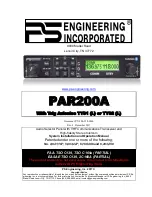
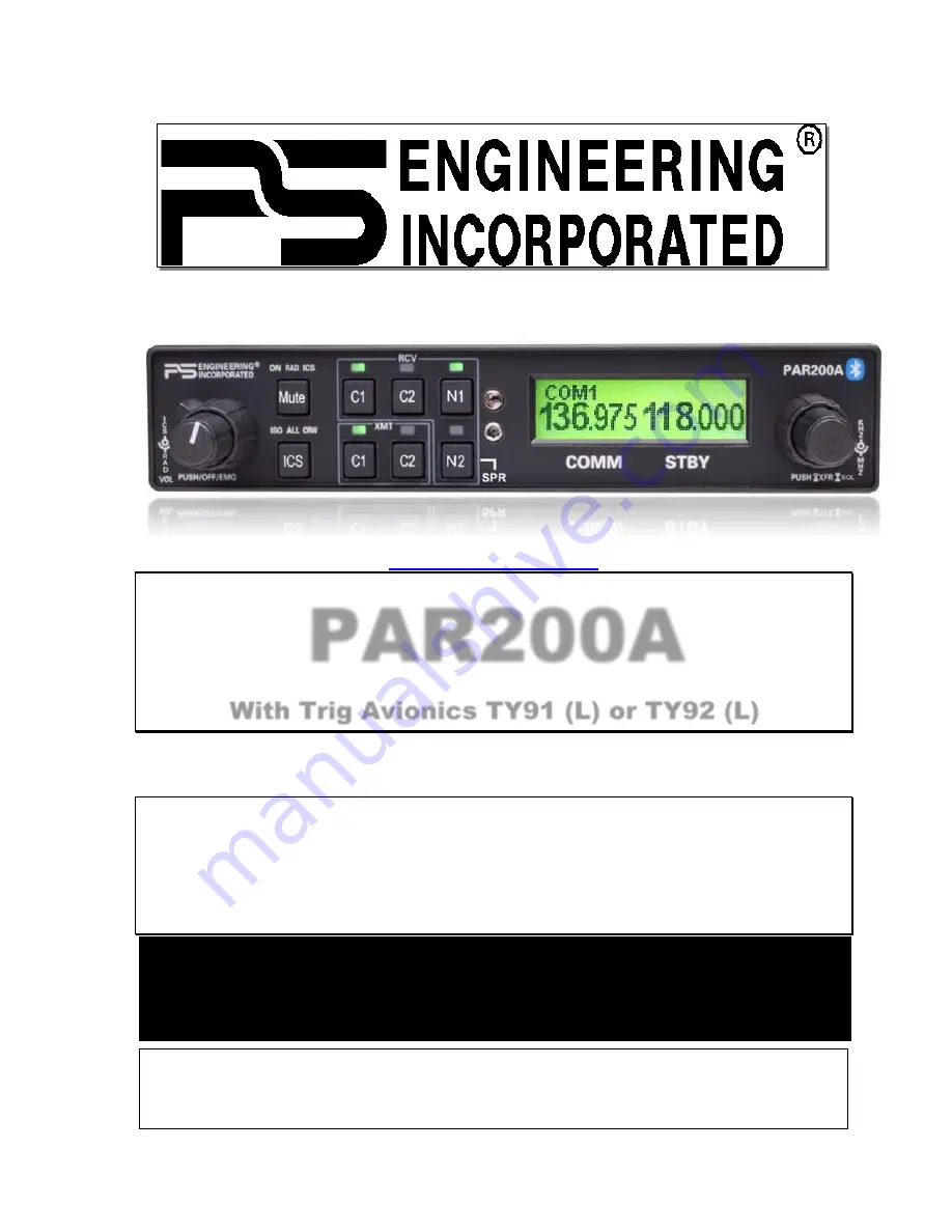
  

PAR200A 

With Trig Avionics TY91 (L) or TY92 (L) 


Document P/N 200-228-0200 

Rev. 4, December 2017


Audio Selector Panel with VHF Communications Transceiver and 

High-fidelity Stereo Intercom 

System Installation and Operation Manual  

Patented under one or more of the following;  

No. 4,941,187; 5,903,227; 6,160,496 and 6,493,450  


PS Engineering, Inc. 2017 ©


Copyright Notice


Any reproduction or retransmittal of this publication, or any portion thereof, without the expressed written permission of PS En-
gineering, Inc. is strictly prohibited. For further information, contact the Publications Manager at PS Engineering, Inc., 9800 
Martel Road, Lenoir City, TN 37772. Phone (865) 988-9800, email contact@ps-engineering.com

.


FAA-TSO C139, TSO C169a (PARTIAL) 

EASA ETSO C139, 2C169A (PARTIAL)


The product warranty is not valid unless this product is installed by an  

Authorized PS Engineering dealer. 

Summary of Contents for PAR200A

Page 1: ...96 and 6 493 450 PS Engineering Inc 2017 Copyright Notice Any reproduction or retransmittal of this publication or any portion thereof without the expressed written permission of PS En gineering Inc i...

Page 2: ...TERFACE 2 3 2 5 TY91 92 VHF COM INTERFACE 2 4 2 5 1 TY91 CONNECTOR TRIG TY91 L TY92 L 05 ONLY 2 4 2 5 2 INTERFACING THE TY91 92 L AS SINGLE COM 1 OR COM 2 2 4 2 5 3 ANTENNA CABLE 2 4 2 5 4 TY91 92 TNC...

Page 3: ...IN STEREO INSTALLATION 3 6 3 8 3 INTERCOM MODES 8 3 7 3 9 BLUETOOTH OPERATION 3 7 3 9 1 BLUETOOTH TELEPHONE CONNECTION 3 7 3 9 2 TELEPHONE TEL OPERATION 3 7 3 10 MUSIC INPUTS 3 8 3 10 1 MUSIC MUTING 9...

Page 4: ...can switch two transceivers Com 1 Com 2 and two receivers Nav 1 Nav 2 A Bluetooth TELEPHONE feature allows the PAR200A to interface the aircraft headset s and Bluetooth enabled cellular devices Warni...

Page 5: ...y be installed only following 14 CFR Part 43 or the applicable airworthiness requirements 1 1 2 Trig TY91 92 Series The VHF Communication Radio Trig Avionics TY91L TY92L is EASA and FAA approved under...

Page 6: ...nse 3 dB 300 Hz 6000 Hz Music Freq Response 3 dB 10 Hz 26 kHz TY91L VHF Transceiver Specifications Radio Type Amplitude Modulation AM Aircraft Transceiver Channels Transmit receive 760 channels 25KHz...

Page 7: ...x D6 3 plus 1 5 for harness W 66mm xH 48mm x D 160 plus 35mm for harness Weight 77 lbs 350 kg FCC ID VZI00879 1 6 EQUIPMENT SUPPLIED One ea of the following items Model Description PS Part Number Trig...

Page 8: ...red e Headphones 150 Stereo up to 4 as required f Microphones up to 4 as required g VHF Communication antenna 118 137 MHz VSWR 2 1 FAA TSO approved is recommended h Mounting hardware for TY91 as appro...

Page 9: ...nformation regarding substitute TSO Aircraft Equipment 2 2 Unpacking and Preliminary Inspection Use care when unpacking the equipment Inspect the units and parts supplied for visible signs of shipping...

Page 10: ...B for more information Failure to use correct techniques may result in improper operation electrical noise or unit failure Damage caused by improper installation will void the PS Engineering warranty...

Page 11: ...h high performance active noise canceling headsets cannot improve on older avionics that were designed for cabin speaker use PS Engineering makes no claim that the audio panel will provide a noise fre...

Page 12: ...COM 2 In the event of a failure the PAR200A will be in fail safe and COM 1 can be used The PAR200A must be configured with an installation strap when PAR200A radio is being used as COM 2 by applying...

Page 13: ...Slide 25 mm 1 inch of heat shrink tubing over the cable 2 Slide the outer crimp sleeve over the cable it must go on before securing the center contact 3 Crimp the center contact to the cable 4 Insert...

Page 14: ...mode in the PAR200A is also compatible with cellular telephones with Bluetooth Hands free headset interface There is no wiring required all functions are handled in the Bluetooth tele phone The PAR200...

Page 15: ...in structions J5 Switch 6 Cell phone sidetone created by audio panel OFF No cell phone sidetone ON Table 2 3 Telephone sidetone switch 2 6 3 Swap Mode When a momentary normally open push button switc...

Page 16: ...for intercom connection configurations It is critical to the proper operation of this system to have this connector wiring made in accordance with these diagrams Use 2 and 3 conductor MIL spec cable...

Page 17: ...on or radio reception The four muting modes are controlled by the front panel Mute button See 3 9 for more information CAUTION Local oscillators and internal signals from entertainment equipment can c...

Page 18: ...0 228 0200 For installations in very noisy aircraft a reduction in the intercom microphone input gain might be desirable The PAR200A has two DIP switches located on the main board that can switch the...

Page 19: ...in the split mode when the frequencies of the two air craft radios are adjacent and or the antennas are physically close together PS Engineering makes no expressed or implied warranties regarding the...

Page 20: ...the 8 33 mode Bandwidth kHz Frequency Displayed 25 118 00000 118 000 8 33 118 00000 118 005 8 33 118 00833 118 010 8 33 118 01666 118 015 25 118 02500 118 025 8 33 118 02500 118 030 8 33 118 03333 11...

Page 21: ...Audio Low 18 No connect 19 Nav 2 Audio 19 No connect 20 Nav 2 Audio Low 20 Swap 21 No Connect 21 Swap Low 22 Unswitched 3 Low 22 Music 1 All Headsets 23 No Connect 23 Music 1 L 24 No Connect 24 Music...

Page 22: ...m operation 6 Push the Com 1 Xmt select button lower row 7 Verify that both of the C1 buttons light Verify that transmit button LED Light Emitting Diode near the mic selector is not blinking If the LE...

Page 23: ...both high and low end of the frequency band 118 000 to 136 975 MHz if possible 2 15 2 TELEPHONE Checkout On the ground not flying activate the TELEPHONE mode using the Bluetooth device Verify that the...

Page 24: ...er switch controls all audio selector panel functions and the intercom All pushbutton selections and menu modes except Bluetooth telephone association will be remembered and return to the last state w...

Page 25: ...In essence switching the mic selector will not override prior selection of COM receiver audio 3 3 1 1 Split Mode The split mode can be activated at any time by pressing the C1 and C2 XMT buttons at th...

Page 26: ...y select knob until ASQ OFF is displayed on the screen Press again until ASQ ON and this will re enable the radio squelch ASQ will reset to ON with power cycle or radio PTT 3 7 1 Frequency Selection 6...

Page 27: ...accept this as STBY frequency NOTE If you do not push the small knob the frequency will not change to the stored and reverts to STBY Figure 3 5 Frequency Recall 3 7 2 Radio Squelch To defeat the autom...

Page 28: ...ds an audible ticking to make you aware which is the active standby It will be important to remember which frequency is active and which is standby to avoid answering a transmission on the standby fre...

Page 29: ...briefly This is normal The IntelliVox is designed to work with normal aircraft cabin noise levels 70 dB and above It loves air plane noise Therefore it may not recognize speech and clip syllables in...

Page 30: ...phone and then enter the access code 0000 when the phone detects the PAR200A on the list of available devices This process will be necessary for any phone to be used and only one cell phone can be as...

Page 31: ...Mode Standard Music Distribution Music 1 All Headsets Music Source ICS Mode All Crew ISO All Crew ISO Music 1 Blue tooth Input Crew Crew Copilot Crew Pass Crew Pass Copilot Pass Music 2 Input Pass Pa...

Page 32: ...Mute OFF None Radio Mute Muted RAD ICS Mute Muted ICS The passenger s intercom also has a SoftMute circuit If the passengers hear the radio or talk on the inter com the music will mute If the audio pa...

Page 33: ...S Engineering SHALL NOT BE LIABLE FOR INCIDENTAL OR CONSEQUENTIAL DAMAGES This warranty does not cover a defect that has resulted from improper handling storage or preservation or unrea sonable use or...

Page 34: ...ed PTT switches will be required for both the pilot and copilot Modifications to the PTT are required See details below Push To Talk Modifications When received from the manufacturer an after market P...

Page 35: ...d from Back 15 30 44 1 16 31 15 30 44 1 16 31 Ground Lug Ground Lug 475 440 0001 x2 Back plate assy 475 009 0001 ground lug x2 475 440 0001 x2 Screww washer Ground lug detail Rear plate detail not to...

Page 36: ...200 228 0200 Appendix B Rev 4 DEC 2017 Tray and cutout dimensions Caution Apply steady pressure to the bezel while screwing the unit into the tray to ensure even seating of the unit and connectors 6 1...

Page 37: ...inim um 24AW G 3 Allm icandheadphonejac ksm us t beisolatedfromground 4 Allshieldedw iresm us t beM IL22750or 27500 5 U nsw itc hedinputsarealw ay spresentedto crewheadphones regardles sofSP Rsw itc h...

Page 38: ...3 Pi ns 8 and 9 connected thr oug h a 3 A br eaker to air cr aft power for the audio panel Br eaker s must be pul l type 4 Al l shielded wires must be MIL 22750 or 27500 5 For music di stri bution inf...

Page 39: ...s indicated 3 Useinsulatingwashers onall jack s Jack s must beelectricallyfloating 4 Connectshields at expansionendonly 5 Passenger v olum econtrol is adjustedat theaudiopanel using theouter k nob 6 P...

Page 40: ...egrated VHF communications con troller and intercommunications system 2 Description Installation as described in manufacturer s installation manual referenced on FAA Form 337 including interface with...

Page 41: ...tested to Category B 5 Minute Humidity 6 0 Equipment tested to Category A Shock 7 0 Equipment tested Standard B Operational 7 2 Equipment tested to Category E Crash Safety 7 3 Equipment tested to Cate...

Reviews: