
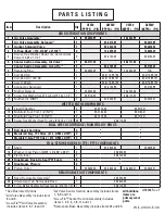
P U M P D E S I G N A T I O N S Y S T E M
C A U T I O N S & W A R N I N G S
B A S I C T R O U B L E S H O O T I N G
S U G G E S T E D I N S T A L L A T I O N
VELOCITY PLASTIC PUMP
Engineering
Operation &
Maintenance
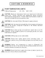
PUMP TEMPERATURE LIMITS:
PVDF and Polypropylene
4°C – 79°C
(40°F - 175°F)
CAUTION: Maximum temperature limits are based upon mechanical
stress only. Certain chemicals will signifi cantly reduce maximum
safe operating temperatures. Consult Chemical Resistance Guide for
chemical compatibility and temperature limits.
CAUTION: Do not exceed 6.9 bar (100 psig) air supply pressure.
CAUTION: Verify the chemical compatibility of the process and cleaning
fl uid to the pump’s component materials in the Wilden Chemical
Resistance Guide.
CAUTION: Plastic series pumps are made from plastic that is not UV-
stabilized. Direct sunlight exposure for prolonged periods can cause
deterioration of plastic.
CAUTION: V2550 pumps are not submersible.
CAUTION: Always wear safety glasses when operating pump. If
diaphragm rupture occurs, fl uid being pumped may be forced out air
exhaust.
WARNING: Before any maintenance or repair is attempted, the
compressed air line to the pump should be disconnected and all air
pressure allowed to bleed from the pump.
WARNING: Ensure that the air supply line is clear of debris. Use of a 5µ
(micron) in-line air fi lter is recommended.
LEGEND
V2550 / XXXXX / XXX / XX /XXX/
XXXX
O-RINGS
VALVE SEAT
MODEL
VALVE BALLS
DIAPHRAGMS
WETTED PARTS &
OUTER PISTON
AIR VALVE
CENTER SECTION
SPECIALTY
CODE
(if applicable)
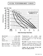
V 2 5 5 0 P E R F O R M A N C E C U R V E
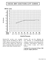
V 2 5 5 0 D R Y S U C T I O N - L I F T C U R V E
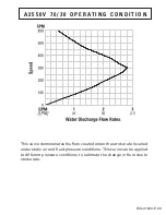
A 2 5 5 0 V 7 0 / 3 0 O P E R A T I N G C O N D I T I O N
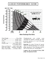
A 2 5 5 0 V P E R F O R M A N C E C U R V E
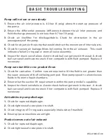
Pump will not run or runs slowly:
1. Ensure the air inlet pressure is 0.3 bar (5 psig) above the start-up pressure of
the pump.
2. Ensure the differential pressure (difference between the air inlet pressure and
fl uid discharge pressure) is not less than 0.7 bar (10 psig).
3.
Check air line/fi lter for blockage/debris. Check for obstruction in the air
passageways of the pump.
4. Check for objects in the pump that would obstruct the movement of internal parts.
5. Check for severe air leakage (blow-by) coming from the air exhaust. This could
indicate a failed O-ring seal or worn air valve assembly.
6. Inspect for check valve failure. A worn check ball can get stuck in the seat. A check
ball can swell and become stuck if not compatible with fl uid pumped. Replace if
necessary.
Pump runs but little or no product fl ows:
1. Check for cavitation. Confi rm vacuum required to lift the fl uid is not greater than
the vapor pressure of the fl uid being pumped. Slow pump speed to allow viscous
fl uids to fl ow into liquid chambers.
2. Ensure that the suction lift requirement is within the pump model’s capability.
3. Inspect for check valve failure. A worn check ball can get stuck in the seat. A check
ball can swell and become stuck if not compatible with fl uid pumped. Replace if
necessary.
Air bubbles in pump discharge:
1. Check for ruptured diaphragm.
2. Check tightness of outer piston to shaft.
3. Check integrity of O-ring seals, especially intake side of manifold.
4. Ensure pipe connections are airtight.
Product comes out of air exhaust:
1. Check for ruptured diaphragm.
2. Check tightness of outer piston to shaft.
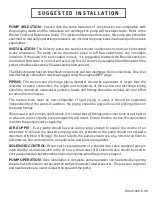
PUMP SELECTION:
Ensure that the pump materials of construction are compatible with
the pumping media and the immediate surroundings the pump will be subjected to. Refer to the
Wilden Chemical Resistance Guide. For optimum life and performance, the pump size should be
specifi ed so that daily operation parameters are not near the pump’s maximum rated performance
capabilities.
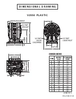
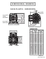
INSTALLATION:
The Velocity pump has two foot-mount confi gurations and can be mounted
in any orientation. The pump can be mounted in place or left free standing for use in multiple
locations. If the pump is to be mounted in place, it is suggested to attach the Base Assembly to
the desired horizontal or vertical surface using four (4) screws (not supplied) and then attach the
pump to the Base Assembly (See Assembly Instructions).
The Velocity pump has two inlet fl uid connections and two discharge fl uid connections. One inlet
and discharge connection must be plugged using the supplied NPT plugs.
PIPING:
The suction and discharge piping diameter should be equivalent or larger than the
diameter of pump connection, the length and complexity of the suction and discharge piping
should be minimized, unnecessary elbows, bends and fi ttings should be avoided, all in an effort
to reduce friction losses.
The suction hose must be non-collapsible. If rigid piping is used, it should be supported
independently of the pump. In addition, the piping should be aligned to avoid placing stress on
the pump fi ttings.
When used in self-priming applications, it is critical that all fi ttings and connections are airtight or
a reduction or loss of pump suction capability will result. Ensure that the suction lift requirement
is within the pump model’s capability.
AIR SUPPLY:
Every pump should have an airline large enough to supply the volume of air
necessary to achieve the desired pumping rate. Air pressure to the pump should not exceed a
maximum of 6.9 bar (100 psig). For best results, the pumps should use a 5µ (micron) air fi lter to
eliminate air-line contaminants, a needle valve and pressure regulator.
SOLENOID CONTROL:
When start-stop operation of a standard air valve equipped pump is
controlled by a solenoid valve in the air line, a three-way (3/2) solenoid valve should be used to
vent pressurized air between the solenoid and pump when the pump is stopped.
PUMP OPERATION:
Once installation is complete, pump operation can be started by opening
the air shut-off valve (do not exceed the pump’s maximum rated pressure). The pressure regulator
and needle valve are used to adjust the speed of the pump.
Ship Weight .........................2 kg (4 lb)
Air Inlet ........................... 6 mm (1/4”)
Inlet .................................. 6 mm (1/4”)
Outlet ............................... 6 mm (1/4”)
Suction Lift ...............4.3 m Dry (14.2’)
6.2 m Wet (20.4’)
Disp. per Stroke
1
....... 0.04 L (0.01 gal)
Max. Flow Rate ....21.6 lpm (5.7 gpm)
Max. Size Solids ......... 0.8 mm (1/32”)
1
Displacement per stroke was
calculated at 4.8 bar (70 psig) air inlet
pressure against a 2.1 bar (30 psig)
head pressure.
Example: To pump 12.5 lpm (3.3 gpm)
against a discharge head of 2.1 bar
(30 psig) requires 4.1 bar (60 psig) and
10.4 Nm
3
/h (6.1 scfm) air consumption.
Caution: Do not exceed 6.9 bar (100
psig) air supply pressure.
Suction-lift curves are created
using pumps operating at 305 m
(1000’) above sea level. This chart is
meant to be a guide only. There are
many variables which can affect the
pump’s operating characteristics.
Suction lift can be affected by
the number of intake/discharge
elbows, viscosity of pumping fl uid,
elevation (atmospheric pressure),
pipe friction losses and other
factors.
Caution: Do not exceed 6.9 bar (100
psig) air supply pressure.
DIAPHRAGMS
TSS = FULL-STROKE PTFE W/ SANIFLEX
BACK-UP O-RING
ZWS = WIL-FLEX™ [Santoprene
®
(Three Black Dots)]
VALVE BALLS
TF = PTFE (White)
WF = WIL-FLEX™ [Santoprene
®
(Three Black Dots)]
VALVE SEAT
K = KYNAR
P = POLYPROPYLENE
VALVE SEAT O-RING
TV = PTFE-ENCAP. FKM
WF = WIL-FLEX (Santoprene
®
)
SPECIALTY CODES
0150 Accu-Flo, 24V DC Coil
0151 Accu-Flo, 24V AC/12V Coil
0155 Accu-Flo, 110V AC Coil
MODEL
V2550 = 6 mm (1/4”) VELOCITY
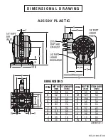
A2550V = 6 mm (1/4”) ACCU-FLO™
WETTED PARTS & OUTER PISTON
KK = PVDF / PVDF
PP = POLYPROPYLENE / POLYPROPYLENE
AIR CHAMBER / CENTER BLOCK
PP = POLYPROPYLENE
AIR VALVE
A = ALUMINUM (ACCU-FLO Only)
E = PET
MATERIAL CODES
This curve demonstrates the fl ow created when the stroke rate is varied
under static air and fl uid pressure conditions. This curve can be applied
to different pressure conditions to estimate the change in fl ow due to
stroke rate.
5
[8]
4
[7]
3
[5]
.30+ .25
KEY
.20 .15
2
[3]
1
[2]
1 2 3 4
[4] [8] [11] [15]
Ship Weight .........................2 kg (4 lb)
Air Inlet ........................... 6 mm (1/4”)
Inlet .................................. 6 mm (1/4”)
Outlet ............................... 6 mm (1/4”)
Suction Lift ...............4.3 m Dry (14.2’)
6.2 m Wet (20.4’)
Disp. per Stroke
1
....... 0.04 L (0.01 gal)
Max. Flow Rate ....14.8 lpm (3.9 gpm)
Max. Size Solids ......... 0.8 mm (1/32”)
1
Displacement per stroke was
calculated at 4.8 bar (70 psig) air inlet
pressure against a 2.1 bar (30 psig)
head pressure.
Example: To pump 7.9 lpm (2.1 gpm)
against a discharge head of 2.1 bar (30
psig) requires 4.1 bar (60 psig) and 6.6
Nm
3
/h (3.9 scfm) air consumption.
Caution: Do not exceed 6.9 bar (100
psig) air supply pressure.
WIL-41000-E-06
WIL-41000-E-06
WIL-41000-E-06
WIL-41000-E-06
WIL-41000-E-06
WIL-41000-E-06
WIL-41000-E-06


