


DRINKING WATER SYSTEM
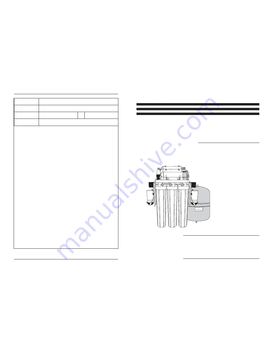
REVERSE OSMOSIS SYSTEM
DRINKING WATER SYSTEM
RO400 400GPD Light Commercial
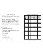
Type of product
Date of purchase
Name
Tel
Address
Memo
01
Introduction of RO
1500
02
What is Reverse Osmosis
03
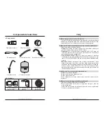
Components& Selections
04
Cartridge filters
05
The parts of RO
1500
07
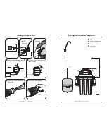
Installation diagram
12
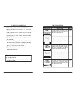
Change filters
13
Change RO membrane
14
Operation regulations
16
FAQ
17
Maintenance checking list
19
Memo
06
Tubing connection diagram
USER'S MANUAL


