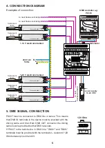
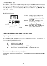
background image

MANUAL 

DMX/0-10V 

Interface 8ch

PX227

R

Summary of Contents for DMX DEMUX 8

Page 1: ...MANUAL DMX 0 10V Interface 8ch PX227 R ...

Page 2: ...loss of DMX signal 7 4 Smoothing function 8 Programming of individual parameters 9 Defining setting the scenes and programs 9 1 Scenes 9 2 Programs 10 Screen blanking 11 Mounting 12 Programming 13 Dimensions 14 Technical data Declaration of conformity Manufacturer reserves the right to make modifications in order to improve device operation Ver 1 4 tel 48 12 626 46 92 fax 48 12 626 46 94 E mail in...

Page 3: ...ng its installation and use 1 Installation of the device and in particular connection of power should be conducted by a suitably qualified person as described in the manual 2 The device can be connected only to the power supply of 12 24V DC stabilized voltage with a load capacity compatible with technical data 3 Protect all cables against mechanical and thermal damage 4 In case of failure of any o...

Page 4: ...7 8 9 10 11 12 19 20 21 22 23 24 Connection GND GND GND GND OUT 1 OUT 2 OUT 3 OUT 4 OUT 5 OUT 6 OUT 7 OUT 8 DC power type DC power type DC power type DC power type DC power type DC power type DMX IN DMX IN DMX IN GND DMX OUT DMX OUT DMX OUT GND 12 24V DC ...

Page 5: ...ne DMX and DMX terminals must be provided with the terminator resistor of 120 Ohm between pins 22 and 23 120 Ohm 5 power supply 12 24 V DC L N DC OK 230 V AC 50 Hz L N terminator 12 24V DC V Electronic Ballast DC 1 10V AC 230V V Electronic Ballast DC 1 10V AC 230V V Electronic Ballast DC 1 10V AC 230V V Electronic Ballast DC 1 10V AC 230V V Electronic Ballast DC 1 10V AC 230V to next fluorescent l...

Page 6: ...Press enter to go to the main menu the display shows ALL Press previous or next to select the programming menu ALL Ind dEF and press enter to confirm 7 PROGRAMMING OF GROUP PARAMETERS Programming in this menu is common to all channels After selecting ALL from the main menu confirm selection by pressing enter then with next or previous select the parameters to be set Adr DMX address of the device C...

Page 7: ...t Cur This will allow you to change the characteristic of channel dimming NEXT NEXT ENTER ENTER ENTER NEXT linear characteristics 1 10 V linear characteristics 0 10 V switched characteristics on off NEXT characteristics defined by the user linear in the range of MIN to MAX V Maximum and minimum values can be set in the range of 0 10 V 7 3 Response to the loss of DMX signal This function is used bo...

Page 8: ...tion on the configuration of the individual programs and scenes can be found in section 9 of the manual Defining setting scenes and programs The HLd function keeps the last DMX value on the output when the signal is lost The device also has the smoothing option Smoothing allows for smooth color changes When this option is enabled switching between successive DMX values sent to channels is smooth w...

Page 9: ...s possible after selecting Adr DMX address can be selected within a range from 1 to 512 8 PROGRAMMING OF INDIVIDUAL PARAMETERS It is also possible to set the output characteristics for each channel linear characteristics 1 10 V linear characteristics 0 10 V switched characteristics on off ENTER NEXT NEXT NEXT NEXT ENTER NEXT NEXT ENTER NEXT ENTER 1 Select deF function to set scenes and programs th...

Page 10: ...o accept the settings press enter Selecting zero means setting the minimum value ENTER 4x NEXT ENTER ENTER ENTER NEXT NEXT NEXT NEXT NEXT NEXT NEXT NEXT NEXT NEXT ENTER NEXT 2x NEXT In order to set the playing speed of the program in the program tab press enter Then enter the program settings step and go to the field Spd Repress enter and select the appropriate value from 0 1 to 25 0 seconds In or...

Page 11: ...tivity buttons unused The device still operates without interfering with other parameters Use any button to restore the backlight In order to activate the screen blanking function 1 Set the SCr function and confirm with enter 2 With next or previous change the value to on and confirm with enter Similarly you should follow in order to switch off this function but then selecting oFF ENTER NEXT 3x NE...

Page 12: ... Installation on the mounting rail 1 Set PX227 diagonally to the rail by hooking the two supports on the rear panel of the unit on the upper part of the assembly strip 2 Pull the latch down using a screwdriver 3 Attach the device to the rail still holding a screwdriver in a latch 4 Release the latch 11 MOUNTING 1 3 2 12 ...

Page 13: ...NEXT NEXT NEXT NEXT NEXT NEXT ENTER ENTER ENTER NEXT ENTER ENTER ENTER NEXT NEXT NEXT NEXT NEXT NEXT NEXT NEXT NEXT NEXT NEXT ENTER NEXT NEXT NEXT NEXT ENTER NEXT ENTER NEXT NEXT NEXT NEXT NEXT NEXT ENTER ENTER NEXT NEXT NEXT NEXT ENTER NEXT ENTER NEXT NEXT ENTER ENTER NEXT ENTER ENTER NEXT NEXT ENTER NEXT NEXT NEXT NEXT ENTER ENTER PREVIEW PREVIEW ENTER ...

Page 14: ...x 250 mA 8 max 30 mA channel 0 10 V 3 screw terminals 70 mm 4 rail modules 86 mm 60 mm DMX channels power supply current consumption number of output channels output carrying capacity voltage on outputs output slots dimensions width height depth 14 TECHNICAL DATA 14 ...

Page 15: ... inż Marek Żupnik Name of producer Manufacturer s address We declare that our product Product name Product code complies with the following standards Additional information Kraków 13 11 2009 DECLARATION OF CONFORMITY according to guide line 2004 108 WE tel 12 626 46 92 fax 12 626 46 94 e mail info pxm pl http www pxm pl ul Przemysłowa 12 30 701 Kraków Konsole teatralne i estradowE Cyfrowe ściemnia...

Reviews: