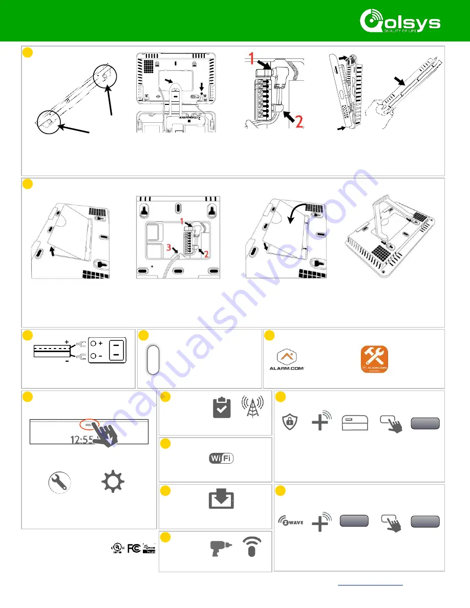
IQ PANEL 2 PLUS QUICK GUIDE
Remove the back plate
WALL MOUNT
Press the buttons on the
bottom to release the back
plate from the panel face
Plug in the power supply
(1) and then clip the wire
to the retainer clip (2)
Secure the back plate to the wall,
then loop the hang strap over the
strain relief hook (1) Run the
antenna through the hole (2)
Place the panel onto the bottom of
the back plate (1) and hinge upward
and snap in place (2). Take care as
you route the antenna into the wall
Plug in the power supply (1)
and then clip the wire to the
retainer clip (2) then into the
strain relief hook (3)
Replace the back cover
Connect the table stand to
the holes on the upper back.
CREATE
ACCOUNT
Settings
Advanced
(default installer
password is 1111)
Swipe down to access settings tray
Connect power supply
WARNING! Use 5.5vDC - 7vDC Power
Supply ONLY
Press and hold the power
button on the right side of
the panel for 3 seconds to
power up
TRY THE
MOBILE TECH
APP
System
Tests
Cell Test
RUN A
CELL TEST
ACCESS ADVANCED SETTINGS
Wi-Fi
CHOOSE
YOUR
NETWORK
CONNECT
WI-FI
Upgrade
Software
UPGRADE
USING
NETWORK
Check for
updates
CHECK FOR
UPDATES
INSTALL
DEVICES
Installation
Devices
Security
Sensors
Auto Learn
Sensor
Tamper or
trip sensor
Customize
as desired*
Add New
Touch
“Add New”
ADD SECURITY SENSORS
ADD Z-WAVE DEVICES
Z-Wave
Devices
Add
Device
Touch
“PAIR” (both
on panel and
on the device)
PAIR
Add New
Touch
“Add New”
Customize
as desired
*If pairing devices with encryption, be sure to
select “S-Line” as the “Source” of the signals
Security Signaling Residential Fire Alarm &
Security Equipment, UL Listed
Conforms to ANSI/UL Standards
Conforms to ANSI/UL Std. S985. 1023. & 1635
Certified to ULC Sub. C1023 & ULC Std. S545
Doc#: IQP2P-QG-01-19 Rev Date: 01/07/19
Qolsys Inc. proprietary. Reproduction without permission is not permitted.
(855) 476-5797
1a
2
3
4
5
6
7
8
11
OPTIONAL MOUNTING: TABLE STAND (INCLUDED IN BOX)
9
10
1b
1
2
1
2


