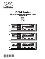
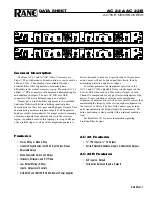
QSC DCM-1, User Manual
The Biamp DCM-1 user manual is an essential tool for maximizing the potential of your Biamp DCM-1 product. With clear instructions and detailed diagrams, this comprehensive manual guides you through setup, operation, and troubleshooting processes. Download your free copy of the Biamp DCM-1 manual from 88.208.23.73:8080.
Share
Download
Reviews:
No comments
Related manuals for DCM-1
AC 22
Brand: Rane Pages: 4
AD 22B
Brand: Rane Pages: 6
AC 23
Brand: Rane Pages: 18

XM6
Brand: Coustic Pages: 15
LXR-7A
Brand: Legacy Pages: 12
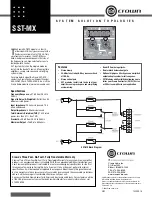
SST-MX
Brand: Crown Pages: 1
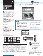
SST-SBSC 3632T
Brand: Crown Pages: 1

F.A.C.T. F-3
Brand: XETEC Pages: 6
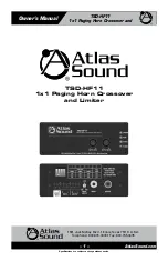
TSD-HF11
Brand: Atlas Pages: 16

S Class
Brand: Samson Pages: 20
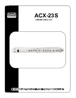
ACX-23S
Brand: DAPAudio Pages: 13
HFEQ
Brand: Hifonics Pages: 10
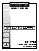
CX-2213
Brand: Nady Audio Pages: 10
SNAXO 362BMR
Brand: NAIM Pages: 24
KLIMAX AKTIV
Brand: Linn Pages: 23
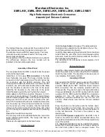
XM16L-3KK
Brand: Marchand Electronics Pages: 12
FDS 310
Brand: BSS Audio Pages: 40
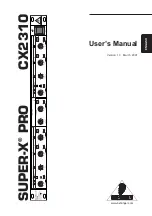
SUPER-X PRO CX2310
Brand: Behringer Pages: 13


