background image

‘ 

Technical  Service Manual 

Document No. 501610 Rev. 07-01-19


XLS Series of Tape Libraries

Summary of Contents for XLS Series

Page 1: ...Technical Service Manual Document No 501610 Rev 07 01 19 XLS Series of Tape Libraries...

Page 2: ...keep the information contained in this document current and accurate as of the date of publication or revision However no guarantee is given or implied that the document is error free or that it is ac...

Page 3: ...evice to others European Union Directive 89 336 EEC and Standard EN55022 Electromagnetic Compatibility This product has been tested and is certified to be compliant with the Class A provisions of the...

Page 4: ...bstances in electrical and electronic equipment in accordance with the European Directive The compliance date is July 1 2006 at which time Qualstar will certify that its tape library products are comp...

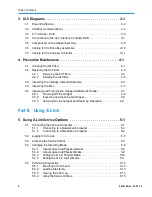
Page 5: ...ty Notices 1 6 1 6 For More Information 1 7 1 6 1 Related Manuals 1 7 1 6 2 Contacting Qualstar 1 10 2 About the XLS 2 1 2 1 Product Overview 2 1 2 1 1 XLS 832700 2 2 2 1 2 XLS 820500 2 3 2 1 3 XLS 81...

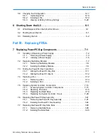
Page 6: ...ng the Gripper and Barcode Reader 4 7 4 5 1 Powering Off the Gripper 4 8 4 5 2 Inspecting and Cleaning the Gripper 4 9 4 5 3 Powering On the Gripper and Resuming Operation 4 11 Part II Using X Link 5...

Page 7: ...1 Removing the Battery Module 7 8 7 2 2 Installing the Battery Module 7 9 7 3 Sliding the Power PC Bay In and Out 7 11 7 3 1 Sliding the Power PC Bay Out 7 11 7 3 2 Sliding the Power PC Bay In 7 12 7...

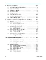
Page 8: ...oor Slots 9 4 9 3 2 Removing Door Slots 9 7 9 4 Replacing a Cartridge Bay with a Drive Bay 9 10 9 4 1 Removing a Cartridge Bay 9 11 9 4 2 Installing a Drive Bay 9 13 9 5 Replacing a Drive Bay with a C...

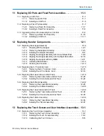
Page 9: ...12 11 12 1 7 Updating the Database 12 12 12 1 8 Scanning the Fiducials 12 13 12 2 Replacing the X Y Controller Card 12 15 12 2 1 Removing the X Y Controller Card 12 16 12 2 2 Installing the X Y Contr...

Page 10: ...Curtain Sensors 14 13 14 5 2 Installing the Light Curtain Sensors 14 18 15 Replacing MEM Components 15 1 15 1 Installing a MEM 15 1 15 1 1 Preparing the LRM 15 3 15 1 2 Removing the X Axis Hard Stop 1...

Page 11: ...1 17 2 Restarting the XLS if All Doors Remained Closed 17 3 17 3 Restarting the XLS if a Door was Opened 17 4 17 3 1 Applying Power 17 5 17 3 2 Performing an Audit 17 6 17 4 Restarting the XLS if the...

Page 12: ...moving the Cartridges B 2 B 1 3 Removing the Equipment Rack B 4 B 2 Packing the XLS B 5 B 2 1 Attaching Ramps to the Pallet B 6 B 2 2 Rolling the Cabinet onto the Pallet B 6 B 2 3 Installing the Shipp...

Page 13: ...XLS Library Technical Service Manual Part I Before You Begin Chapter 1 Getting Started 1 1 Chapter 2 About the XLS 2 1 Chapter 3 XLS Diagrams 3 1 Chapter 4 Preventive Maintenance 4 1...

Page 14: ...501610 Rev 07 01 19 Part I Before You Begin Notes...

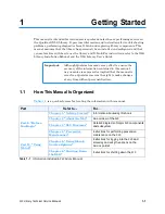
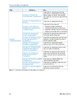
Page 15: ...ual no guarantee is expressed or implied that the manual is error free Qualstar reserves the right to make changes at any time without prior notification 1 1 How This Manual Is Organized Table 1 1 is...

Page 16: ...lacing I O Ports and Fixed Port Assemblies Instructions for replacing I O ports fixed port assemblies and the cartridge magazines in the fixed port assemblies Chapter 12 Replacing Handler Components I...

Page 17: ...this manual Index Alphabetized quick reference for specific topics and terms Table 1 1 Information included in XLS Service Manual continued 1 2 Safety Notices CAUTION The Qualstar XLS Library is a so...

Page 18: ...required to remove and install XLS components Tool 3 4 inch open end wrench 3 8 inch Allen wrench 5 16 inch Allen wrench right angled if possible 1 4 inch Allen wrench 3 16 inch Allen wrench 5 32 inch...

Page 19: ...4 Panduit PLT1M M30 3 inch cable tie 730 0017 6 Loctite 242 Threadlocker 24077 Thread locking adhesive Table 1 3 Materials check list 1 5 Conventions Used in This Manual This section lists the termino...

Page 20: ...r example Each physical library can be partitioned into one or more logical libraries 1 5 3 Safety Notices This manual may include four types of notices Warnings and Caution Notices To avoid personal...

Page 21: ...er to the manuals in Table 1 4 which are available in Adobe Acrobat PDF format from X Link Refer to Part number For XLS 832700 and XLS 820500 Libraries Product Specification 501600 Detailed specificat...

Page 22: ...1 on page 5 1 to connect the library to a standalone computer or Ethernet network 2 Open any of the supported Internet browsers on an attached computer 3 In the address field for the browser type htt...

Page 23: ...cal Service Manual 1 9 5 Select the manual you are interested in Assuming that Adobe Acrobat or Acrobat Reader is installed on your system the PDF file opens See Figure 1 3 Figure 1 3 PDF file of exam...

Page 24: ...ibrary contact an authorized reseller or Qualstar Technical Support Qualstar Corporation 1267 Flynn Road Camarillo CA 93012 Monday Friday 7 00 AM to 4 00 PM PST Phone 805 416 7055 Toll Free 877 886 27...

Page 25: ...nd exporting cartridges from the library Three XLS models are currently available the XLS 832700 the XLS 820500 and the XLS 812300 Shown in Figure 2 1 the library uses two building blocks The Library...

Page 26: ...rives up to 655 cartridges and up to four 10 slot I O ports As an option it can be attached to one or two MEMs Doors 2 Cartridge slots Touch screen Status LEDs I O ports up to 4 Handler barcode reader...

Page 27: ...es up to 20 tape drives up to 465 cartridges and up to four 10 slot I O ports As an option it can be attached to one or two MEMs Cartridge slots Touch screen Status LEDs I O ports up to 4 Door 1 Handl...

Page 28: ...lot I O ports As an option expansion pods can be installed on either side of the library with each expansion pod adding 120 cartridge slots Cartridge slots Touch screen Status LEDs I O ports 1 or 2 Do...

Page 29: ...ouch screen and LEDs see Section 2 2 2 on page 2 10 Robotic handler and barcode reader see Section 2 2 3 on page 2 11 Tape drives see Section 2 2 4 on page 2 14 I O ports see Section 2 2 5 on page 2 1...

Page 30: ...bays Power PC bay Figure 2 6 Rear view of the LRM XLS 832700 shown 2 2 1 Power PC Bay Figure 2 6 on page 2 6 shows the location of the power PC bay at the rear of the LRM The power PC bay houses the p...

Page 31: ...ed MEMs The power supplies are configured in an N 1 arrangement meaning that if one fails the others will handle the load until the failed supply is replaced The power supplies can be replaced while t...

Page 32: ...to Section 3 1 on page 3 2 System Controller Shown in Figure 2 8 on page 2 8 the system controller occupies the right side of the power PC bay and consists of a Linux based computer that controls the...

Page 33: ...ot control or communicate with the tape drives or move data Ethernet connectors The system controller includes two Ethernet connectors for communication across 10 100 Base T Ethernet networks One of t...

Page 34: ...er and communicates with the system controller using a USB interface The driver circuitry for the touch screen resides on the user interface controller behind the front panel The digital signal proces...

Page 35: ...dicate the library s operational status at a glance Status LEDs are also included on the back of each tape drive assembly and each power supply 2 2 3 Robotic Handler and Barcode Reader Shown in Figure...

Page 36: ...up and down the Y axis on a round guide shaft It is moved by a toothed belt which is driven by the Y axis motor The Y motor is also controlled by the X Y controller DCB The Theta axis is the rotating...

Page 37: ...independently turned off and on by the power supply controller The X Y controller also includes the capacitor based energy storage system which allows the robot to be safely parked at the bottom of t...

Page 38: ...r scans each slot to determine which ones contain cartridges It also scans the barcode labels on the cartridges to establish and maintain its cartridge inventory The system controller stores the cartr...

Page 39: ...e connectors each drive carrier includes a cooling fan the drive carrier DCB and a DC to DC power supply A digital signal processor provides communication between the library and the tape drive s seri...

Page 40: ...e bays A drive bay which holds four tape drives can be exchanged with a cartridge bay which holds 30 cartridges and vice versa For safety reasons four tape drive or drive filler assemblies see Figure...

Page 41: ...on the model the XLS can include one two or four I O ports For each I O port that is not installed the library includes 10 additional cartridge storage slots called fixed port assemblies Each I O port...

Page 42: ...dge Slots XLS 832700 XLS 820500 XLS 812300 Cartridge bays up to 210 7 bays up to 120 4 bays up to60 2 bays Rear wall slots1 265 205 205 Door slots 0 110 or 220 0 or 110 not available Fixed port slots...

Page 43: ...o doors All doors have windows for viewing robot operations the front windows in the LRM are blocked if the optional door slots are installed There are also smaller viewing windows on the side panels...

Page 44: ...ect small beams of infrared light toward corresponding detectors The curtain of light formed by the emitters and detectors allows the XLS to precisely monitor all areas within the LRM and MEM cabinets...

Page 45: ...p 66 cm Installed equipment could include a Fibre Channel switch or other ancillary equipment Two versions of the rack option are available The 6U rack 10 5 inches resides entirely within the LRM cabi...

Page 46: ...on Module MEM The MEM derives its power and control from an attached LRM The carousel can rotate in either direction and is driven by a brushless DC motor with optical encoder The handler from an atta...

Page 47: ...unications are routed throughout the XLS Section 3 3 X Y Controller DCB on page 3 6 shows the connections to the X Y controller DCB Section 3 4 Connections to the User Interface Controller DCB on page...

Page 48: ...ounted in removable tape drive assemblies The tape drive assemblies contain the drive carrier DCB and have DC to DC power supplies to provide power for the drives A digital signal processor in the tap...

Page 49: ...ht Carousel Controller PCBA 520957 X Cont ller 5 17 24V Drive Carrier PCBA 520017 Power Supplies 3 3V 5V 12V Drive Carrier PCBA 520017 Power Supplies 3 3V 5V 12V Drive Carrier PCBA 520017 Power Suppli...

Page 50: ...ects the system controller to each of the drive bays while the CAN0 can zero bus connects the system controller to the battery module the robotics the power supply controller the user interface and to...

Page 51: ...ower Power Supply Controller 520437 Power Backplane PCBA 520427 CAN0 CAN1 Aux Connector To Other Drive Bays Left Carous Controlle PCBA 520957 Right Carous Controlle PCBA 520957 Y C troller 0417 Drive...

Page 52: ...y for the Z Theta and User Interface not from the power supply for the X Y Motors However it provides emergency power to both loads 24V X Y Y Axis Motor Driver X Axis Motor Driver J7 J6 J1 J2 Y Axis M...

Page 53: ...02 520787 Light Curtain Front Detector PCBA 521007 01 Curtain RX Digital Signal Processor 520523 01 520807 Light Curtain Rear Detector PCBA 520522 01 Temperature Sensors 520721 01 520721 01 Top Temp...

Page 54: ...ont Detector PCBA 521007 01 Curtain RX Digital Signal Processor 520523 01 520297 01 Light Curtain Rear Detector PCBA 520522 01 Temperature Sensors 520721 01 520721 01 Top Temp Bot Temp 520297 01 Light...

Page 55: ...itters Gripper Hall Effect Sensor Optical Sensor Detector Bar Code Reader Cable 667 0003 0 J3 J100 Digital Signal Processor Solenoid Driver Theta Z Controller PCBA 520217 Z Axis Motor Driver Theta Axi...

Page 56: ...4 520067 02 Drive Bay E Drive Bay D XLS 832700 Drive Bay C Drive Bays 1 2 520067 01 Drive Bay B Power Backplane PCBA 520427 Drive Bay A Bottom Drive Bays 5 6 520067 03 Drive Bay E Drive Bays 3 4 Driv...

Page 57: ...737 02 521020 01 6 Carousel Controller PCBA 520957 01 0 Light Curtain Expansion Emitter PCBA 520817 01 6 520522 03 8 Light Curtain Expansion Emitter PCBA 520817 01 6 520522 04 6 Light Curtain Expansio...

Page 58: ...3 7 Cabling for the Carousel Controller 3 12 501610 Rev 07 01 19 Notes...

Page 59: ...filters help keep dust and dirt from entering the library and degrading the performance of the tape drives and media To ensure the best reliability periodically check and replace the air filters To or...

Page 60: ...has two filters Air filters 3 Figure 4 1 Location of the air filters XLS 832700 shown 2 Inspect the air filters If dirt is clinging to the gray filter you should replace it 3 As required adjust the D...

Page 61: ...ong you want to wait before receiving another alert to check the air filters If you did not need to change the filters enter the number of days until you want to receive a second reminder If the filte...

Page 62: ...820500 and XLS 812300 have two screws and the MEM has two screws Captive screws 3 Figure 4 4 Location of the captive screws on the air filter cover XLS 832700 shown 2 Using a 2 Phillips screwdriver l...

Page 63: ...o the slots on the frame 4 Raise the top of the air filter cover into position 5 Using the Phillips screwdriver tighten the captive screws 4 3 Inspecting the Cartridge Slots and Fiducials As part of t...

Page 64: ...tice broken or worn parts replace the magazine See Section 9 2 on page 9 2 5 Replace any cleaning cartridges in the system reserved slots G46 to G49 See Figure 4 7 Important Be sure that the system re...

Page 65: ...ure that both fans are turning and not making excessive noise If there seems to be a problem replace the fan as described in Section 7 4 on page 7 12 4 Slide the power PC bay back into the library s f...

Page 66: ...n the parts if necessary Section 4 5 2 on page 4 9 3 Power on the gripper and resume operation Section 4 5 3 on page 4 11 Table 4 1 Overview of inspecting and cleaning gripper components 4 5 1 Powerin...

Page 67: ...ens as shown in Figure 4 10 Figure 4 10 Service Utilities page 5 From the Robot section select Power Off Gripper to power off the gripper 4 5 2 Inspecting and Cleaning the Gripper To inspect and clean...

Page 68: ...r pads Figure 4 11 Location of the gripper pads 4 Carefully inspect each pad 5 If you see debris accumulating use a cotton swab moistened with isopropyl alcohol to gently swab the pads and the recesse...

Page 69: ...9 Close any open doors 4 5 3 Powering On the Gripper and Resuming Operation To power on the gripper and resume operation follow these steps 1 From the Robot section of the Service Utilities page selec...

Page 70: ...4 5 Inspecting and Cleaning the Gripper and Barcode Reader 4 12 501610 Rev 07 01 19 Notes...

Page 71: ...XLS Library Technical Service Manual Part II Using X Link Chapter 5 Using X Link Service Options 5 1 Chapter 6 Shutting Down the XLS 6 1...

Page 72: ...Part II Using X Link 501610 Rev 07 01 19 Notes...

Page 73: ...see Section 5 6 on page 5 17 5 1 Connecting the XLS to a Computer This section describes how to connect the XLS to a standalone or networked computer You can skip these instructions if the XLS has alr...

Page 74: ...0 is located on the power PC bay as shown in Figure 5 1 on page 5 1 Figure 5 2 Location of the service port on the XLS 832700 Required tools and equipment Make sure you have the following A standalone...

Page 75: ...ic domain name system DNS you can use the primary Ethernet connector ENET0 for the initial configuration The library hostname qualstarxls will be automatically available to the network To connect the...

Page 76: ...Note The service port for the XLS 832700 is located behind the air filter cover on the front of the library see Figure 5 2 on page 5 2 The service port for the XLS 820500 and XLS 812300 is located on...

Page 77: ...X Link To log into X Link follow these steps 1 Contact the XLS administrator to obtain a user ID and password Make sure that the user ID has been assigned to a user group such as SuperUser or Physical...

Page 78: ...5 2 Logging Into X Link 5 6 501610 Rev 07 01 19 4 Press Log In The X Link Home page opens as shown in Figure 5 6 Figure 5 6 X Link Home page Logical Library View shown...

Page 79: ...2 Select Service View or Show All to display the Service portlet shown in Figure 5 7 Figure 5 7 Service portlet Table 5 1 on page 5 8 describes the options that can be selected from the Service portle...

Page 80: ...ions for the following Putting the XLS in physical mode see Section 5 4 3 on page 5 10 Putting the XLS in logical mode see Section 5 4 4 on page 5 11 5 4 1 About Logical and Physical Libraries Before...

Page 81: ...ay library operation the XLS is in logical mode In logical mode one or more software applications control the library and you interact with X Link from a logical library perspective When you interact...

Page 82: ...could change the internal state of the physical library you must put the XLS in physical mode When you put the XLS in physical mode the following occurs The XLS completes any current or pending operat...

Page 83: ...brary was online when you put the XLS in physical mode it will go back online when you put the XLS in logical mode If a logical library was offline when you put the XLS in physical mode it will remain...

Page 84: ...agnostic procedures from the Service portlet Execute Command see Section 5 5 1 Audit Library see Section 5 5 2 on page 5 13 View SCSI Log see Section 5 5 3 on page 5 14 Service Utilities see Section 5...

Page 85: ...slot and reads each barcode label The resulting inventory includes the following information The empty or full status of every cartridge slot The human readable text from the barcode labels The media...

Page 86: ...of the SCSI commands and messages sent and received by the library Qualstar Technical Support may request that you send them a copy of this log to help debug certain problems Refer to Section 5 6 3 on...

Page 87: ...Save to download and save the file 5 Press Done to exit the page 5 5 4 Using the Service Utilities To access the service utilities follow these steps 1 Access the Service portlet See Section 5 3 on pa...

Page 88: ...n be serviced See Section 12 1 on page 12 2 Power On Gripper Power the gripper back on See Section 12 1 on page 12 2 Home Robot Realign the motor magnetics and reestablish the hard stop and index posi...

Page 89: ...on to establish whether any fiducials were missed during the fiducial scans Carousels Power Off Carousel Left Power off the left or right carousel controller before replacing the carousel motor See Se...

Page 90: ...P site and transfer the appropriate file to your network 3 Log in to X Link using a computer that can access the downloaded file See Section 5 2 on page 5 5 4 From the Home page access the Service por...

Page 91: ...nstructions in Section 5 6 1 on page 5 18 to upload the file 3 From the Home page access the Service portlet See Section 5 3 on page 5 7 4 From the Change Mode section select Physical Mode to put the...

Page 92: ...al log To view or edit the SCSI log settings follow these steps 1 From the Home page access the Service portlet See Section 5 3 on page 5 7 2 From the Change Configuration section select View Edit SCS...

Page 93: ...reen When the shut down process is complete the Fault LED red flashes indicating that it is safe to move the power switch to the off position 6 2 Shutting Down the XLS To shut down the XLS follow thes...

Page 94: ...ccurring when you began the shut down process 8 When the Fault red LED begins flashing finish shutting down the XLS by moving the power switch on the back of the library to the off position as shown i...

Page 95: ...idge Slots and Drive Bays 9 1 Chapter 10 Replacing Frame Components 10 1 Chapter 11 Replacing I O Ports and Fixed Port Assemblies 11 1 Chapter 12 Replacing Handler Components 12 1 Chapter 13 Replacing...

Page 96: ...Part III Replacing FRUs 501610 Rev 07 01 19 Notes...

Page 97: ...bay assembly including the power controller PCBA the power switch breaker and the power connector see Section 7 6 on page 7 21 Slide rails for the power PC bay see Section 7 7 on page 7 25 Figure 7 1...

Page 98: ...on receiving power from the power backplane For this reason be sure both of these slots are occupied before installing additional power supplies Important If a redundant power supply is installed the...

Page 99: ...g at the power supply LEDs shown in Figure 7 3 and comparing them to the LED states described in Table 7 1 LEDs Figure 7 3 Power supply LEDs LED Meaning PWR Good Fault On green Off The power supply is...

Page 100: ...See Figure 7 4 Figure 7 4 Loosening the power supply lock screws 3 Using one hand to grasp the handle and the other to support the power supply s weight carefully slide the supply out of the power PC...

Page 101: ...on 7 1 2 Installing a Power Supply To install a power supply follow these steps 1 As required use a Phillips screwdriver to remove the two 8 32 3 8 Phillips screws that secure the cosmetic cover to an...

Page 102: ...e power supply and try again Do not force it into position Figure 7 7 Inserting a power supply into the power PC bay 4 Push on the power supply to ensure that the connectors are fully seated against t...

Page 103: ...ides instructions for replacing the battery module If the Fault LED is on the battery module needs to be replaced You can replace the battery module while the XLS remains powered on CAUTION The batter...

Page 104: ...ttery module screws 2 Using a Phillips screwdriver remove the two screws and set them aside You will reuse these screws to install the replacement module 3 Using one hand to grasp the handle and the o...

Page 105: ...into the open battery module slot 7 2 2 Installing the Battery Module To install the battery module follow these steps 1 Orient the new module so that the label is to the top and the handle is to the...

Page 106: ...illuminates the battery module may not be charged It can take up to 10 minutes for the battery in the replacement module to fully charge 4 Using a Phillips screwdriver replace the two screws and turn...

Page 107: ...However you must power down the library before replacing any system controller components including the PCI cards and the hard drive or the power PC bay itself Required tools and equipment Make sure...

Page 108: ...C bay back into place follow these steps 1 Holding the power PC bay by a power supply handle or by the flanges on either side slide the bay into the library s frame 2 Replace the four screws two on ei...

Page 109: ...an 7 4 1 Removing a Fan To remove a fan follow these steps 1 Follow the instructions in Section 7 3 1 on page 7 11 to slide the power PC bay out 2 Using your fingers or a Phillips screwdriver turn the...

Page 110: ...fan 2 Turn the thumb screw clockwise until hand tight 3 Follow the instructions in Section 7 3 2 on page 7 12 to slide the power PC bay back into the library s frame 7 5 Replacing System Controller C...

Page 111: ...ctrostatic discharge ESD If possible use a grounded static protection wristband If a wristband is not available touch a known grounded surface Required tools and equipment Make sure you have the follo...

Page 112: ...gure 7 16 Removing the system controller cover 4 Lift the cover off of the system controller 7 5 2 Replacing PCI Cards This section provides instructions for removing any of the following PCI cards CA...

Page 113: ...m controller See Figure 7 17 Figure 7 17 Location of the screws on the EMI shield 3 Remove the shield 4 Disconnect any cables connected to the card you want to remove 5 Remove the screw securing the c...

Page 114: ...Ds 5 and 6 will be assigned to HBA D As a result any logical libraries connected to these ports will have invalid nexus settings HBA A HBA B HBA C HBA D HBA A HBA B HBA C HBA D Original port IDs Port...

Page 115: ...7 5 3 Replacing the Hard Drive This section provides instructions for replacing the hard drive Important Before replacing the hard drive contact Qualstar Technical Support Removing the Hard Drive To r...

Page 116: ...e 2 Reconnect the following cables 4 pin cable to the power back plane IDE ribbon cable to the motherboard 3 Reinstall the system controller cover as described in Section 7 5 4 7 5 4 Replacing the Sys...

Page 117: ...avoid damaging the XLS you must shut down the library before removing or installing power PC bay assembly CAUTION Ensure that the environment is free of conditions that could cause electrostatic disch...

Page 118: ...3 and battery module see Section 7 2 1 on page 7 8 you will install them in the replacement power PC bay 4 Follow the instructions in Section 7 3 1 on page 7 11 to slide the power PC bay out of the l...

Page 119: ...GA and USB cables 10 Slide the USB and VGA cables out through the bay 11 Remove the following components you will install them in the new power PC bay Hard drive see Removing the Hard Drive on page 7...

Page 120: ...crew the ground strap 16 Push on the slide rail release levers and slide the bay out 7 6 2 Installing the Power PC Bay Assembly To replace the power PC bay assembly follow these steps 1 Insert the new...

Page 121: ...e the EMI shield 9 Reconnect the Ethernet cable 10 Replace the Power supplies see Section 7 1 2 on page 7 5 Battery module see Section 7 2 2 on page 7 9 11 Reconnect the power cord Make sure the latch...

Page 122: ...ide rail to power PC bay 7 7 2 Installing the Slide Rails To replace the slide rails follow these steps 1 Using a Phillips screwdriver replace the three screws attaching the slide rail to the side of...

Page 123: ...e filler assembly is removed Although it is not required you may want to put the XLS in physical mode to prevent the software applications from timing out when a tape drive is removed Procedure overvi...

Page 124: ...vailable from the Logical Libraries portlet However if you use the options available from the Logical Libraries portlet you must specify a SCSI element address for the tape drive instead of a physical...

Page 125: ...ocation becomes inaccessible to the logical library For this reason Cartridges cannot be moved to an offlined tape drive by the software application that controls the logical library Cartridges cannot...

Page 126: ...ect Offline Tape Drive from the list of options below the table However if you select Offline Tape Drive you must enter the address of the tape drive The Take Tape Drive Offline page opens as shown in...

Page 127: ...es page as described in Section 8 1 on page 8 2 2 If the tape drive contains a cartridge and you want to remove it before powering off the drive eject and unload the cartridge from the tape drive Note...

Page 128: ...f the table 6 Check the Drive Status LED on the back of the tape drive assembly If the LED is amber or off it is safe to remove the tape drive See Figure 8 5 Figure 8 5 Status LEDs on Fibre Channel dr...

Page 129: ...ve screws counterclockwise until loose See Figure 8 6 Figure 8 6 Loosening the tape drive assembly screws 4 Using one hand to support the tape drive s weight at the front of the carrier carefully slid...

Page 130: ...rives used in the XLS must be installed into drive carriers at the factory 8 5 Installing a Tape Drive To install a tape drive assembly in the library follow these steps 1 Using one hand to support th...

Page 131: ...the two captive screws clockwise until tight See Figure 8 9 Figure 8 9 Tightening the tape drive assembly screws 4 As required repeat steps 1 3 to install a drive filler assembly shown in Figure 8 10...

Page 132: ...le However if you select Power On Tape Drive you must enter the address of the tape drive The Power On Tape Drive page opens as shown in Figure 8 11 Figure 8 11 Power On Tape Drive page physical libra...

Page 133: ...ive is brought online For example it does not recalibrate the position before onlining the tape drive If the tape drive was taken offline but not physically replaced If the position was already calibr...

Page 134: ...Drive page opens as shown in Figure 8 13 Figure 8 13 Calibrate Tape Drive page physical library version shown 4 Press Yes to calibrate the tape drive 5 Confirm that Calibrated is now reported in the S...

Page 135: ...described in Section 8 1 on page 8 2 2 In the Status Offline column of the tape drives table select Offline Important As an alternative you can select Online Tape Drive from the list of options below...

Page 136: ...8 8 Bringing a Tape Drive Online 8 14 501610 Rev 07 01 19 Notes...

Page 137: ...LS cartridge magazine with storage slots for five cartridges and two fiducials Fiducials are the black and white triangles that are mounted on either side of every cartridge magazine There is also a f...

Page 138: ...a cartridge magazine Required tools and equipment Make sure you have the following Replacement cartridge magazine Two 6 32 3 8 Phillips screws 2 Phillips screwdriver magnetized if possible 9 2 1 Remo...

Page 139: ...can the operation will fail 9 2 2 Installing a Cartridge Magazine To install a cartridge magazine follow these steps 1 Locate the cartridge magazine mounting holes on the frame 2 Insert two 6 32 3 8 P...

Page 140: ...ng door slots Step Task Refer to 1 Shut down the library and power it off Section 6 2 on page 6 1 2 Install the magazine faceplates Installing the Magazine Faceplates on page 9 4 3 Install the cartrid...

Page 141: ...re 9 3 Figure 9 3 DOR barcode label and bracket back of door shown 5 On the back of the door locate the holes for the 11 magazine faceplates 6 Insert three 6 32 x 5 16 flat head screws through the out...

Page 142: ...le Figure 9 5 Location of mounting holes for cartridge magazines on magazine faceplate 2 Use two 6 32 x 3 8 pan head screws to attach a cartridge magazine to one side of the magazine faceplate Be sure...

Page 143: ...pdate the hardware configuration and scan the fiducials and inventory Section 17 5 on page 17 12 Table 9 3 Overview of removing door slots CAUTION Before removing door slots consider that all logical...

Page 144: ...ips screwdriver remove the screws from the upper and lower holes on each of the upper magazines See Figure 9 6 Figure 9 6 Removing a cartridge magazine 6 Remove the remaining cartridge magazines Remov...

Page 145: ...ceplates 4 On the back of the door locate the two holes for the DOR barcode label bracket 5 Using a Phillips screwdriver insert two screws through the bracket and into the door See Figure 9 8 Figure 9...

Page 146: ...to Section 9 4 1 on page 9 11 to remove the cartridge bay and Section 9 5 2 on page 9 20 to install the replacement Procedure overview Table 9 4 provides an overview of replacing a cartridge bay with...

Page 147: ...iver Empty drive bay Four 6 32 3 8 Phillips screws Four tape drive assemblies or drive filler assemblies 9 4 1 Removing a Cartridge Bay To remove a cartridge bay follow these steps 1 Shut down the lib...

Page 148: ...k of the library carefully slide the cartridge bay out of the frame 6 If you are installing a drive bay go to the next section Otherwise refer to Section 9 5 2 Installing a Cartridge Bay on page 9 20...

Page 149: ...e two screws holding the drive bay plate to the front of the bay See Figure 9 11 Remove screws Figure 9 11 Removing the drive bay plate 2 Remove the plate and screws and set them aside 3 Orient the em...

Page 150: ...into position 6 Secure the bay with four 6 32 3 8 Phillips screws two on the left and two on the right See Figure 9 13 Insert screws Insert screws Figure 9 13 Installing the drive bay screws view fro...

Page 151: ...f the four slots See Section 8 5 on page 8 8 CAUTION For safety and UL compliance a tape drive assembly or drive filler assembly must be installed in all tape drive slots If there are empty tape drive...

Page 152: ...refer to Section 9 5 1 on page 9 17 to remove the drive bay and Section 9 4 2 on page 9 13 to install the replacement Procedure overview Table 9 5 provides an overview of replacing a drive bay with a...

Page 153: ...emove a drive bay follow these steps 1 Put the library in physical mode which takes all logical libraries offline See Section 5 4 3 on page 5 10 2 Unlock and open the doors 3 Push the eject buttons on...

Page 154: ...ent bay Remove screws Remove screws Figure 9 17 Removing the drive bay screws 7 From the front of the library open the right door 8 Use a Phillips screwdriver to remove the two screws that hold the dr...

Page 155: ...bay cable from its connector 12 From the back of the library slide the tape drive assembly completely out of the frame 13 If you are installing a cartridge bay go to the next section Otherwise refer...

Page 156: ...bay so that the cartridge slots are to the front and the flanged edges are on top See Figure 9 20 Cartridge slots Flange Figure 9 20 Cartridge bay orientation 2 From the back of the library lift the...

Page 157: ...t screws Insert screws Figure 9 21 Installing the cartridge bay screws view from the back 5 As required insert cartridges into each slot 6 Refer to Section 17 5 on page 17 12 to power on the library u...

Page 158: ...9 5 Replacing a Drive Bay with a Cartridge Bay 9 22 501610 Rev 07 01 19 Notes...

Page 159: ...off Section 6 2 on page 6 1 2 Remove front panel cartridges Section 10 1 1 3 Remove the air filter cover Section 10 1 2 on page 10 3 4 Detach the cables Section 10 1 3 on page 10 4 5 Remove the front...

Page 160: ...oid behind the front panel as shown in Figure 10 1 I O port solenoid Figure 10 1 I O port solenoid 5 Press the solenoid release button to open the I O port See Figure 10 2 Figure 10 2 Pressing the I O...

Page 161: ...XLS 832700 has three screws and the XLS 820500 and XLS 812300 have two screws Captive screws 3 Figure 10 3 Location of the captive screws on the air filter cover XLS 832700 shown 2 Using a 2 Phillips...

Page 162: ...Interface PCBA Touch screen video LCD power Touch screen USB interface Figure 10 5 Cable coupling block 2 Disconnect all five cables from the coupling block Touch screen video LCD power Touch screen...

Page 163: ...or interlock sensor 6 On the ceiling of the frame locate the cable that connects the right front light curtain to the front panel See Figure 10 8 Light curtain cable to front panel Figure 10 8 Light c...

Page 164: ...steps 1 Locate the five Phillips screws attaching the front panel to the frame See Figure 10 9 Remove screws Remove screws Figure 10 9 Location of front panel screws 2 Using a Phillips screwdriver rem...

Page 165: ...other padding before leaning the front panel against any surface 10 2 Installing the Front Panel Procedure overview Table 10 2 provides an overview of installing the front panel Step Description Refe...

Page 166: ...sert the front panel in the frame follow these steps 1 Lift the front panel into position so that the base of the panel rests on the frame and the flange fits behind the frame See Figure 10 11 Figure...

Page 167: ...ect the light curtain cable to its connector on the ceiling of the frame See Figure 10 12 Light curtain cable to front panel Figure 10 12 Light curtain cable connector 2 Connect the cables to both the...

Page 168: ...onnectors are keyed and can be inserted in only one direction Light curtain lower emitters User Interface PCBA Touch screen video LCD power Touch screen USB interface Figure 10 15 Cable coupling block...

Page 169: ...and inventory CAUTION If you replaced a fixed port assembly with an I O port follow the instructions in Section 17 5 on page 17 12 to restart the library Do not close the doors until you have updated...

Page 170: ...refully slide the panel up until you can lift the hooks out of the corresponding slots on the frame See Figure 10 17 Figure 10 17 Removing a side panel 10 3 2 Installing a Side Panel To install a side...

Page 171: ...s XLS Library Technical Service Manual 10 157 2 Replace the two screws in the holes at the bottom of the panel See Figure 10 18 Figure 10 18 Installing the side panel 3 Refer to Section 17 3 on page 1...

Page 172: ...10 3 Replacing a Side Panel 10 14 501610 Rev 07 01 19 Notes...

Page 173: ...Task Refer to 1 Shut down the library and power it off Section 6 2 on page 6 1 2 Remove the front panel Section 10 1 on page 10 1 3 Remove the I O port Section 11 1 1 4 Install the I O port Section 11...

Page 174: ...nt for the I O ports to open freely CAUTION The touch screen is easily scratched Protect the screen with a soft cloth or other padding before leaning the front panel against any surface 3 Locate the I...

Page 175: ...embled screws securing the black cosmetic cover to the front of the I O port See Figure 11 3 Screw hidden by sheet metal Figure 11 3 Location of screws for the I O port cosmetic cover 6 Locate the I O...

Page 176: ...ers or the end of a screwdriver release the I O port spring from either its upper or lower attachment point See Figure 11 5 Upper attachment Lower attachment Figure 11 5 I O port spring 10 Locate the...

Page 177: ...t I O port assemblies The racheting mechanism should face the outer edge of the frame 2 From the back of the front panel insert the I O port assembly into the front panel 3 Lay the front panel and I O...

Page 178: ...e I O port See Figure 11 1 on page 11 2 7 Using needle nosed pliers or spring attachment tool reattach the spring See Figure 11 5 on page 11 4 8 Reattach the I O port damper with the two screws See Fi...

Page 179: ...e fixed port Section 11 2 2 on page 11 8 4 Power on the library and scan the fiducials and inventory Section 17 4 on page 17 8 Table 11 2 Overview of replacing a fixed port assembly Required tools and...

Page 180: ...three screws and set them aside 7 Remove the fixed port assembly CAUTION Do not turn on the library before reinstalling the fixed port assembly or an I O port 11 2 2 Installing a Fixed Port Assembly...

Page 181: ...s section provides instructions for replacing a fixed port assembly with an I O port Shown in Figure 11 10 two or four I O ports can be installed on the front of the LRM Each I O port holds 10 cartrid...

Page 182: ...u will need to allow time for the library to re scan all fiducials and barcodes Required tools and equipment Make sure you have the following 2 Phillips screwdriver with a 5 inch or longer blade magne...

Page 183: ...he three screws and set them aside 5 Remove the fixed port assembly CAUTION Do not turn on the library before reinstalling the fixed port assembly or an I O port 11 3 2 Installing an I O Port To insta...

Page 184: ...e the four I O port screws See Figure 11 12 Screws Screws Figure 11 12 I O port screws Important If you do not have a magnetized screwdriver simply slide one hand under the tray at the base of the I O...

Page 185: ...crews and two pre assembled screws See Figure 11 13 Screw hidden by sheet metal Figure 11 13 Location of screws for the I O port cosmetic cover 10 Replace the front panel as described in Section 10 2...

Page 186: ...11 3 Upgrading a Fixed Port Assembly to an I O Port 11 14 501610 Rev 07 01 19 Notes...

Page 187: ...e Section 12 1 Removing and replacing the X Y controller card see Section 12 2 on page 12 15 Removing and replacing the X axis cable and cat track see Section 12 3 on page 12 19 Removing and replacing...

Page 188: ...1 Power off the gripper Section 12 1 1 2 Remove the gripper Section 12 1 2 on page 12 5 3 Replace the gripper Section 12 1 3 on page 12 7 4 Align the gripper assembly with the left back wall Section 1...

Page 189: ...Gripper alignment cartridge Qualstar part number 620059 See Figure 12 2 Figure 12 2 Gripper alignment cartridge 12 1 1 Powering Off the Gripper To power off the gripper assembly follow these steps 1...

Page 190: ...19 Figure 12 3 Service portlet 3 From the Change Configuration section of the Service portlet select View Edit Hardware Configuration The View Edit Hardware Configuration page opens as shown in Figur...

Page 191: ...f the gripper Important The XLS itself can remain powered on when you replace the gripper assembly 12 1 2 Removing the Gripper Assembly To remove the gripper assembly follow these steps 1 Open the doo...

Page 192: ...mechanism to release the cable from the connector Figure 12 6 Releasing the gripper flex cable from the connector 4 Using tweezers or needle nosed pliers with smooth blades very carefully pull the fle...

Page 193: ...he gripper assembly follow these steps 1 Orient the gripper assembly so that flex cable is facing the flex adapter card See Figure 12 5 on page 12 5 2 Place the gripper assembly on top of the X beam m...

Page 194: ...needle nosed pliers with smooth blades reattach the flex cable to the flex cable adapter card Push the locking mechanisms in to lock the cable in place See Figure 12 10 Flex cable connector Figure 12...

Page 195: ...the Left Back Wall To align the gripper assembly with the left back wall follow these steps 1 Open the door s 2 Insert the gripper alignment cartridge into the left column on the back wall as follows...

Page 196: ...tion 12 1 5 12 1 5 Aligning the Gripper Assembly with the Right Back Wall To align the gripper assembly with the right back wall follow these steps 1 Insert the gripper alignment cartridge into the ri...

Page 197: ...nstalled MEMs follow these steps 1 Insert the gripper alignment cartridge into slot 36 of the carousel use whichever column of slots is facing forward See Figure 12 12 Important Make sure the alignmen...

Page 198: ...vide the resulting number by two This is the Theta Back Wall value c Add 180 to the Theta Back Wall value to obtain the Theta Front Wall value Note that If the Theta Back Wall value starts with 14 the...

Page 199: ...portlet select View Edit Hardware Configuration The View Edit Hardware Configuration page opens 5 Select I O Ports from the Fiducials section of the page then wait while the XLS scans the fiducials on...

Page 200: ...canned select the appropriate option from the Fiducial section of the page Select All Slots to scan the fiducials on the cartridge magazine Select I O Ports to scan the fiducials on the I O ports Sele...

Page 201: ...et the X Y controller card includes the drivers for the X and Y axes of the handler The card also includes the capacitor based energy storage system that allows the robot to be safely parked at the bo...

Page 202: ...2 Open the right door 3 On the floor of the XLS on the right hand side locate the two X Y LEDs See Figure 12 15 X Y LEDs Figure 12 15 LEDs on the X Y controller card 4 Ensure that both LEDs are off in...

Page 203: ...t side of the card CAUTION Be very careful as you disconnect the X motor cables The cables are fragile and very easily damaged Power cable X motor cables Screws 4 Y flex cable Figure 12 16 Location of...

Page 204: ...er card follow these steps 1 Reposition the card in the frame 2 Replace the screws that attach the card to the frame 3 Replace the X Y controller card cover 4 Replace the four screws that attach the c...

Page 205: ...age 12 20 4 Install the X axis and cat track Section 12 3 2 on page 12 22 5 Replace the gripper Section 12 1 3 on page 12 7 6 Power on the library Section 17 4 1 on page 17 8 7 Align the gripper assem...

Page 206: ...ripper assembly as described in Section 12 1 2 on page 12 5 3 Locate the connection between the cat track flex cable and the flex cable adapter card See Figure 12 18 Cat track flex cable Flex cable ad...

Page 207: ...nnector and pulling back on the cable 8 Remove all of the screws from the X beam access cover See Figure 12 20 Figure 12 20 Location of screws on X beam access cover left side of XLS 832700 shown Note...

Page 208: ...S 812300 have 10 screws 7 Replace the two screws attaching the cat track flex cable to the mounting bracket for the flex cable adapter 8 Reattach the flex cable to the adapter card See Figure 12 18 on...

Page 209: ...Table 12 3 Overview of replacing the X motor assembly Required tools and equipment Make sure you have the following 1 Phillip screwdriver 2 Phillips screwdriver Cable tie cutters 7 64 inch T handle or...

Page 210: ...access cover left side shown Note The X beam cover for the XLS 832700 has 12 screws 6 large and 6 small the X beam covers for the XLS 820500 and XLS 812300 have 10 screws 5 Slide the gripper all the...

Page 211: ...f the center idler pulleys See Figure 12 24 Push here Idler pulleys Figure 12 24 Removing the X beam belt 8 Disconnect the X motor cable from the X motor adapter card Cut the cable ties securing the X...

Page 212: ...S for clarity 10 Use a 7 64 inch T handle or standard Allen wrench to remove the four mounting screws Important As you remove the fourth screw support the motor with one hand to prevent it from droppi...

Page 213: ...our mounting screws See Figure 12 27 Figure 12 27 Location of mounting screws for the X motor X beam removed for clarity 4 Connect the X motor cable to the X motor adapter card See Figure 12 28 Cable...

Page 214: ...motor belt and center idler pulleys X beam removed for clarity 7 To check the tension of the X motor belt position your forefinger on the lower belt and your thumb on the upper rail about 8 inches 20...

Page 215: ...screw to the lower right See Figure 12 31 Locking screw Adjustment screw Figure 12 31 Allen screws for adjusting the tension of the X belt b Loosen the locking screw by 1 2 of a turn c To tighten the...

Page 216: ...at track shown in Figure 12 32 Y axis cable Y axis cat track Figure 12 32 Y axis cable and cat track Required tools and equipment Make sure you have the following 2 Phillips screwdriver 12 5 1 Removin...

Page 217: ...4 Ensure that both LEDs are off indicating that the capacitors on the X Y controller card have fully discharged It may take as long as 25 minutes after you power off the XLS for the capacitors to ful...

Page 218: ...ble attached to the X motor adapter card 6 Disconnect the flex cable from the card by releasing the locking mechanism on the connector and pulling back on the cable 7 Remove the two Phillips screws fr...

Page 219: ...b Remove the cat track 12 5 2 Installing the Y Axis Cable and Cat Track To install the Y axis cable and cat track follow these steps 1 Put the cat track and cable into position 2 If you are replacing...

Page 220: ...panel remains in place Procedure overview Table 12 4 provides an overview of replacing the Y motor assembly Step Task Refer to 1 Shut down the library and power it off Section 6 2 on page 6 1 2 Remov...

Page 221: ...le See Figure 12 37 Figure 12 37 Location of screws for the front access grille 4 Locate the X Y controller card 5 Disconnect the Y motor encoder and Y motor power cables from the X Y controller card...

Page 222: ...Using a 5 32 inch T handle or standard Allen wrench remove the four Allen screws from the Y motor mounting bracket as shown in Figure 12 39 Figure 12 39 Location of screws on Y motor mounting bracket...

Page 223: ...Allen screws on the Y motor assembly mounting bracket See Figure 12 39 on page 12 36 3 Locate the two belt tensioning plates just above the Y motor gear pulley See Figure 12 40 Figure 12 40 Location o...

Page 224: ...3 5 mm Figure 12 41 Measuring the gap between the two tension plates 5 To adjust the belt tension follow these steps a Loosen by 1 4 turn only the four Allen screws that hold the top tension plate in...

Page 225: ...To loosen the belt turn the adjustment screw counterclockwise which allows the tension plates to slide farther apart d When the gap between the two tension plates is between 3 and 5 mm tighten the fou...

Page 226: ...12 6 Replacing the Y Motor Assembly 12 40 501610 Rev 07 01 19 Notes...

Page 227: ...owing components Touch screen assembly see Section 13 1 User interface assembly which includes the five status LEDs see Section 13 2 on page 13 5 13 1 Replacing the Touch Screen Assembly Shown in Figu...

Page 228: ...brate the touch screen Section 13 1 3 on page 13 5 8 Scan the fiducials and inventory Section 17 4 2 on page 17 10 Table 13 1 Overview of replacing the touch screen assembly Precautions CAUTION Ensure...

Page 229: ...it against a wall CAUTION The touch screen is easily scratched Protect the screen with a soft cloth or other padding 3 Disconnect the four touch screen cables from their connectors as shown in Figure...

Page 230: ...p and remove it from the front panel 13 1 2 Installing the Touch Screen Assembly To install the touch screen follow these steps 1 Lean the front panel against a wall 2 Slide the touch screen into posi...

Page 231: ...ce PCBA which controls many of the library s sensors including the door I O port and light curtain sensors and the front panel LED display Figure 13 4 User interface assembly on back of front panel Pr...

Page 232: ...teps 1 Shut down the library and power it off See Section 6 2 on page 6 1 2 Remove the front panel as described in Section 10 1 on page 10 1 and lay it flat on the floor with the touch screen facing d...

Page 233: ...p temperature LCD button Touch screen I O port 4 I O port 2 Right cabinet RCAB door USB I O port 3 I O port 1 Left cabinet LCAB door Curtain receive RX Curtain transmit TX System Bottom temperature Fi...

Page 234: ...f the PCBA CAUTION Be sure not to pinch the cables between the PCBA and the cover 4 Replace the six screws that secure the cover to the user interface PCBA See Figure 13 6 on page 13 7 5 Reattach the...

Page 235: ...th the front panel in place 14 1 Replacing a Door Interlock Sensor This section provides instructions for replacing a door interlock sensor in the XLS 832700 XLS 820500 XLS 812300 or a MEM Each door u...

Page 236: ...1 Removing a Door Interlock Sensor To remove a door interlock sensor follow these steps 1 Shut down the library and power it off See Section 6 2 on page 6 1 2 Remove the air filter cover from the fron...

Page 237: ...Phillips screws that attach the metal bracket to the sensor you will reuse this part when you install the replacement part See Figure 14 3 Bracket screws Figure 14 3 Door interlock sensor bracket 14 1...

Page 238: ...des an overview of replacing a door lock solenoid Step Task Refer to 1 Shut down the library and power it off Section 6 2 on page 6 1 2 Remove the door lock solenoid Section 14 2 1 3 Install the door...

Page 239: ...id cable to the frame 5 Disconnect the solenoid cable from the cable connector 6 Using a Phillips screwdriver remove the three screws attaching the solenoid to the front panel 7 Remove the solenoid as...

Page 240: ...n page 17 4 Table 14 3 Overview of replacing an I O port open sensor Precautions CAUTION Ensure that the environment is free of conditions that could cause electrostatic discharge ESD If possible use...

Page 241: ...the I O port open sensor 5 Using a 1 4 inch nut driver remove the two nuts attaching the sensor bracket to the front panel Important Be careful not to drop the nuts 6 Remove the sensor and the bracket...

Page 242: ...he I O port solenoid Section 14 4 2 on page 14 9 5 Replace the front panel Section 10 2 on page 10 7 6 Power on the library Section 17 4 on page 17 8 Table 14 4 Overview of replacing an I O port solen...

Page 243: ...14 6 I O port solenoid Figure 14 6 I O port solenoid 4 Use a 5 64 inch Allen wrench to remove the screw connecting the solenoid release to the bracket 5 Using a Phillips screwdriver remove the three s...

Page 244: ...m a slot If the door s are closed and one of these beams of light is broken the XLS prevents the handler from moving to avoid hitting a protruding cartridge The beams of light curtain at the front of...

Page 245: ...tain Bottom left light curtain Bottom right light curtain Bottom light curtain sensors emitters Cable coupling block Top rear light curtain Top left light curtain Top right light curtain Top light cur...

Page 246: ...rs are at the bottom Left access emitters top Left door emitters top Right access emitters top Right door emitters top Left access detectors bottom Left door detectors bottom Right access detectors bo...

Page 247: ...rview of replacing a light curtain sensor Precautions CAUTION Ensure that the environment is free of conditions that could cause electrostatic discharge ESD If possible use a grounded static protectio...

Page 248: ...820500 or XLS 812300 LRM Bottom right emitter Located in the front of the cabinet on the right side LRM Bottom rear emitter Located at the rear of the cabinet in front of the bottom most cartridge or...

Page 249: ...detector Attached to the ceiling of the cabinet on the right side Top left detector Top rear detector Top right detector LRM Top rear detector Attached to the ceiling of the cabinet just in front of...

Page 250: ...s 14 16 501610 Rev 07 01 19 Description Location MEM Bottom right detectors access and door MEM Top left emitter access MEM Top left emitter door MEM Top right emitter access Figure 14 9 Location of t...

Page 251: ...urtain cable from its connector 5 Remove the screws holding the light curtain bracket in place 6 Carefully remove the PCBA and bracket from the cabinet 7 After removing the light curtain PCBA and brac...

Page 252: ...cation of screws for front light curtain PCBA b Set the screws and the metal brackets aside you will reuse these parts when replacing the PCBAs 14 5 2 Installing the Light Curtain Sensors To install a...

Page 253: ...rear light curtain only c Replace the six screws attaching the two interconnected PCBAs to the bracket See Figure 14 14 Figure 14 14 Location of screws for rear light curtain PCBAs For the front PCBA...

Page 254: ...14 5 Replacing Light Curtain Sensors 14 20 501610 Rev 07 01 19 6 Reconnect the cables to the PCBA 7 Apply power to the library See Section 17 3 on page 17 4...

Page 255: ...g the carousel locks Section 15 1 3 on page 15 6 5 Connecting the carousel controller cable Section 15 1 4 on page 15 8 6 Attaching the MEM to the LRM Section 15 1 5 on page 15 10 7 Lowering the level...

Page 256: ...crewdriver 3 8 inch Allen wrench 5 16 inch Allen wrench 5 32 inch Allen wrench 1 4 inch Allen wrench Precision level Equipment shipped with the MEM Two bullet nose alignment pins Six 5 16 18 x 1 2 inc...

Page 257: ...n page 6 1 2 On the side of the LRM where you will install the MEM locate the two Phillips screws at the base of the side panel 3 Using a 2 Phillips screwdriver remove the two screws See Figure 15 2 F...

Page 258: ...usel controller cable on the side of the LRM 7 Cut the cable ties holding the cable to the frame 15 1 2 Removing the X Axis Hard Stop When shipped the X axis horizontal axis on the handler includes tw...

Page 259: ...will install the MEM CAUTION To avoid damage to the equipment never remove the two outer stops To remove an inner hard stop follow these steps 1 If you will install a MEM to the left of the LRM locat...

Page 260: ...must release the carousel locks before installing the MEM To release the carousel locks follow these steps 1 Locate the two brackets under the left and right sides of the carousel as shown in Figure...

Page 261: ...screws on the right side of the bracket screws 3 and 4 in Figure 15 8 are shipping locks and function to keep the carousel from rotating 3 Use a 5 16 inch Allen wrench right angled if possible to rem...

Page 262: ...ervice use 5 Turn the carousel by hand to ensure that it rotates smoothly and without encountering any obstructions The carousel will be hard to turn CAUTION Do not use the edges of the cartridge slot...

Page 263: ...0 Removing the MEM s lower back panel 2 Route the cable as follows Out the side of the LRM Into the side of the MEM Out the back of the MEM 3 Connect the cable to either of the two keyed connectors on...

Page 264: ...gnment pin Figure 15 12 Inserting an alignment pin into the MEM upper hole shown 3 Confirm that the pins align with the holes on the LRM Important If the pins do not align with the holes adjust the le...

Page 265: ...their washers and into the holes 10 Tighten the screws with a 1 4 inch Allen wrench Important If the holes on the MEM do not align with the holes on the LRM adjust the leveling feet on the MEM see Sec...

Page 266: ...floor Then turn the nut two more complete turns See Figure 15 15 1 Lower the foot to the floor 2 Turn the nut 2 more turns Figure 15 15 Extending a leveling foot 4 Repeat steps 2 and 3 to extend the t...

Page 267: ...t be tight against the floor before you install the cartridges CAUTION To avoid damaging the base of the carousel do not install cartridges in the carousel slots unless the carousel supports are fully...

Page 268: ...EM To install the side panel on the MEM follow these steps 1 Holding the side panel with both hands place the panel next to the MEM and carefully lower it until the hooks on the panel engage with the...

Page 269: ...Link starts and the log in page is displayed 4 After the power on processes are complete check the status of the LEDs as follows From the back of the library look at each tape drive assembly and conf...

Page 270: ...Gripper with the MEM You must align the gripper to the MEM to ensure that the new slots can be accessed To align the gripper follow these steps 1 Log in to X Link 2 Select Service View to display the...

Page 271: ...ew Edit Hardware Configuration 4 From the Robot section select Position Robot which powers on the robots homes all axes including any carousels and positions the gripper to an easily accessible locati...

Page 272: ...Select Get Robot Status X Link displays information about the robot s position 9 Write down the values for Theta Position TPOS and X Position XPOS 10 Move the X beam down by hand so that it is not blo...

Page 273: ...press this button the XLS adds the new MEM slots to its internal databases 5 Locate the TPOS and XPOS values you obtained while aligning the gripper to the carousel 6 Enter the TPOS value in the Thet...

Page 274: ...n the fiducials on the I O ports Select All Slots to scan the fiducials on the cartridge magazines Select Tape Drives to scan and calibrate the tape drives 5 When the fiducial scans are complete selec...

Page 275: ...electronic lock for the MEM doors Required tools and equipment Make sure you have the following 2 Phillips screwdriver 15 2 1 Removing the Door Solenoid Assembly 1 Shut down the library and power it...

Page 276: ...follow these steps 1 Attach the white cable from the solenoid to the red and yellow cable inside the XLS Important The cable is keyed and can be attached in only one way Make sure that the connector s...

Page 277: ...5 3 4 on page 15 30 Table 15 2 Overview of replacing the carousel motor Required tools and equipment Make sure you have the following 2 Phillips screwdriver 3 16 inch Allen wrench Standard pliers Cabl...

Page 278: ...et shown in Figure 15 26 Figure 15 26 Service portlet 4 From the Change Mode section select Physical Mode to put the library in physical mode See Section 5 4 3 on page 5 10 for more information 5 From...

Page 279: ...disengaged 15 3 2 Removing the Carousel Motor To remove the carousel motor follow these steps 1 Access the carousel motor bracket and alignment pin as follows If the MEM is to the right of the LRM rem...

Page 280: ...er panel to the back of the MEM See Figure 15 28 Figure 15 28 Removing the MEM s lower back panel 3 Disconnect the carousel motor encoder and power cables from the carousel controller card then cut th...

Page 281: ...and bottom screws and washers Save these parts you will use them on the replacement motor 6 On the carousel motor mount locate the belt tensioning screw See Figure 15 31 Belt tensioning screw Figure...

Page 282: ...these steps 1 From the back of the MEM position the carousel motor assembly into the mounting bracket 2 Align the motor with the mounting bracket and carefully push down on the alignment pin to lock t...

Page 283: ...mount 7 If the gap is too large tighten the belt tensioning screw or If the gap is too small loosen the belt tensioning screw 8 When the belt is tensioned correctly tighten the top and bottom adjustm...

Page 284: ...Utilities page opens as shown in Figure 15 27 on page 15 24 4 Power on the carousel controller using the appropriate command as follows If you want to power on the carousel attached to the left side o...

Page 285: ...ection 16 1 on page 16 2 3 Install the expansion pod mounting hardware Section 16 2 on page 16 5 4 Remove the X axis hard stop Section 16 3 on page 16 9 5 Attach the expansion pod to the XLS 812300 Se...

Page 286: ...et head screws 3 5 16 flat washers 3 Left expansion pod 3 8 16 x 1 2 socket head screws 3 3 8 flat washers 3 16 1 Removing the Side Panels from the XLS 812300 To remove the side panels from the XLS 81...

Page 287: ...of the corresponding slots on the frame See Figure 16 2 Figure 16 2 Removing the front side panel 4 Repeat steps 2 and 3 to remove the rear side panel 5 Use a T20 Torx driver to remove the five screw...

Page 288: ...2300 16 4 501610 Rev 07 01 19 6 Using a 2 Phillips screwdriver remove the six screws that attach the center mounting rail to the side of the XLS 812300 See Figure 16 3 Figure 16 3 Removing the center...

Page 289: ...ller cable See Figure 16 4 Figure 16 4 Expansion pod controller cable on the side of the XLS 812300 2 Cut the cable ties holding the cable to the frame 3 In the accessory kit for the expansion pod loc...

Page 290: ...Insert the bullet nose end of the alignment pin into the hole at the top of the XLS 812300 6 Secure the top hinge mount using three flat head screws Ensure that the hinge pins point upward See Figure...

Page 291: ...ough the channel on the bottom hinge mount See Figure 16 7 Figure 16 7 Routing the expansion pod controller cable through the bottom hinge mount 8 Attach the bottom hinge mount to the XLS 812300 using...

Page 292: ...the expansion pod is to the left of the XLS 812300 Use three 3 8 x 1 2 socket head screws and three 3 8 inch flat washers Install the screws from the inside of the XLS That is insert them into the XLS...

Page 293: ...nstalled the handler is prevented from traveling too far to the left and right When an inner hard stop is removed the handler can reach into an attached expansion pod You need to remove the inner hard...

Page 294: ...hard stop from the X axis See Figure 16 11 Do not remove Figure 16 11 Removing the X axis hard stop right side shown 16 4 Attaching the Expansion Pod to the XLS 812300 To attach the expansion pod to t...

Page 295: ...12300 into the corresponding holes on the pod See Figure 16 12 Figure 16 12 Attaching an expansion pod left side shown with fixed port removed 3 Connect the expansion pod controller cable to the keyed...

Page 296: ...ure 16 14 Top hole Top alignment pin Figure 16 14 Aligning the expansion pod with the XLS 812300 5 Insert three 10 32 x 1 1 4 socket head screws through the three holes on the outside of the expansion...

Page 297: ...u removed in Section 16 1 on page 16 2 See Figure 16 16 for the location of the three top screws Figure 16 16 Installing the side panel on the expansion pod 2 Insert one screw in the hole at the botto...

Page 298: ...and the log in page is displayed 4 After the power on processes are complete check the status of the LEDs as follows From the back of the library look at each tape drive assembly and confirm that the...

Page 299: ...to the Expansion Pod You must align the gripper to both columns of slots in the expansion pod to ensure that the new slots can be accessed To align the gripper follow these steps 1 Log in to X Link 2...

Page 300: ...Configuration 4 From the Robot section select Position Robot which powers on the robots homes all axes including any carousels and positions the gripper to an easily accessible location 5 When the rob...

Page 301: ...t cartridge aligns with the gripper assembly guide rod and that it is flush with the gripper and the cartridge slot b Select Get Robot Status X Link displays information about the robot s position c W...

Page 302: ...Pods section of the page locate whichever drop down list is appropriate for the expansion pod you just installed that is either Carousel Pod installed on left or Carousel Pod installed on right 3 Sel...

Page 303: ...n your library scanning magazine fiducials can take several hours 3 When the fiducial scan has completed select Dump Database The results of the fiducial scan displays as shown in Figure 16 21 This re...

Page 304: ...logical library inventories with the results of the physical library scan 8 From the General section of the page select Lock Doors 9 Press Done to return to the Home page 10 As required add the new ex...

Page 305: ...at occurred when the XLS was shut down as follows All doors remained closed For example you replaced a component at the back of the library such as an HBA or the power PC bay For instructions see Sect...

Page 306: ...Hardware Configuration Close doors Scan and calibrate fiducials Scan sync inventory No Service Utilities Close doors Scan and calibrate fiducials Scan sync inventory A door was opened but the fiducia...

Page 307: ...ove the power switch on the back of the library to On See Figure 17 2 Figure 17 2 Power switch in on position 3 Wait for the power on processes to complete During power on The status LEDs on the front...

Page 308: ...ink and put the XLS in logical mode See Section 5 4 4 on page 5 11 17 3 Restarting the XLS if a Door was Opened This section includes instructions for applying power to the XLS and scanning the cartri...

Page 309: ...ses to complete During power on The status LEDs on the front panel flash intermittently The tape drives perform their own power on processes For information refer to the documentation for the tape dri...

Page 310: ...fully charged It can take up to 10 minutes for the battery to fully charge after the library s power is restored From the front of the library look at the Attention LED which should be off 17 3 2 Perf...

Page 311: ...From the Run Diagnostics section select Audit Library The Audit Library page opens as shown in Figure 17 5 Figure 17 5 Audit Library page 6 Select Audit entire library 7 Press Yes to confirm that you...

Page 312: ...would use these instructions after performing any of the following procedures Replacing a cartridge magazine Replacing a cartridge bay with another cartridge bay Replacing a drive bay with another dri...

Page 313: ...m the XLS the Drive Status LEDs on the back of the tape drive assemblies are green X Link starts and the log in page is displayed 4 After the power on processes are complete check the status of the LE...

Page 314: ...G50 2 Close any open door s and I O ports 3 Log in to X Link 4 From the Home page select Service View to display the Service portlet 5 From the Run Diagnostics section of the Service portlet select S...

Page 315: ...ort Fiducials to scan the fiducials on the I O ports Select Scan Magazine Fiducials to scan the fiducials on the cartridge magazines Select Scan Calibrate Tape Drives to scan and calibrate the tape dr...

Page 316: ...iguration For example you would use these instructions after performing any of the following procedures Replacing a drive bay with a cartridge bay or vice versa Replacing a fixed port assembly with an...

Page 317: ...k starts and the log in page is displayed 4 After the power on processes are complete check the status of the LEDs as follows From the back of the library look at each tape drive assembly and confirm...

Page 318: ...e bay with a cartridge bay see Section 9 5 on page 9 16 Important You do not need to update the hardware configuration if you Replaced a drive bay with another drive bay Replaced a cartridge bay with...

Page 319: ...page select Service View to display the Service portlet shown in Figure 17 10 Figure 17 10 Service portlet 4 From the Change Configuration section of the Service portlet select View Edit Hardware Conf...

Page 320: ...cal mode 6 In the Bays Doors or I O Ports section of the page select the position then specify the component you installed For example if you replaced a cartridge bay with a drive bay in bay position...

Page 321: ...ry after applying power follow these steps 1 Make sure that there are no cartridges in any of the tape drives and that the calibration cartridge is installed in slot G50 2 Close any open doors and I O...

Page 322: ...the I O ports Select All Slots to scan the fiducials on the cartridge magazines Select Tape Drives to scan and calibrate the tape drives 8 When the fiducial scans are complete select Calibrate All to...

Page 323: ...XLS Library Technical Service Manual Part IV Reference Appendix A Library Addresses A 1 Appendix B Packing the XLS B 1 Appendix C Torque Values C 1 Glossary GL 1 Index 1 1...

Page 324: ...Part IV Reference 501610 Rev 07 01 19 Notes...

Page 325: ...suming that drive bays are installed instead of cartridge bays Figure A 2 on page A 3 The tape drives as viewed from the back Figure A 3 on page A 4 XLS 820500 All cartridge slots on the rear wall and...

Page 326: ...22 C21 C20 C19 C18 C17 C16 C15 C14 C13 C12 C11 C10 C09 C08 C07 C06 C05 C04 C03 C02 C01 D60 D59 D58 D57 D56 D55 D54 D53 D52 D51 D50 D49 D48 D47 D46 D45 D44 D43 D42 D41 D40 D39 D38 D37 D36 D35 D34 D33 D...

Page 327: ...B57 B56 B55 B54 B53 B52 B51 B50 B49 B48 B47 B46 B45 B44 B43 B42 B41 C60 C59 C58 C57 C56 C55 C54 C53 C52 C51 C50 C49 C48 C47 C46 C45 C44 C43 C42 C41 D60 D59 D58 D57 D56 D55 D54 D53 D52 D51 D50 D49 D48...

Page 328: ...the physical addresses of the tape drives in the XLS 832700 as viewed from the back 4H 3H 2H 1H 4G 3G 2G 1G 4F 3F 2F 1F 4E 3E 2E 1E 4D 3D 2D 1D 4C 3C 2C 1C 4B 3B 2B 1B 4A 3A 2A 1A Figure A 3 Physical...

Page 329: ...09 C09 D09 E09 F09 G09 B08 C08 D08 E08 F08 G08 B07 C07 D07 E07 F07 G07 B06 C06 D06 E06 F06 G06 B05 C05 D05 E05 F05 G05 B04 C04 D04 E04 F04 G04 B03 C03 D03 E03 F03 G03 B02 C02 D02 E02 F02 G02 B01 C01 D...

Page 330: ...7 D27 E27 F27 G27 B26 C26 D26 E26 F26 G26 1E 2E 3E 4E 1D 2D 3D 4D 1C 2C 3C 4C 1B 2B 3B 4B Figure A 5 shows the physical addresses for the rear wall of the XLS 820500 assuming that five drive bays are...

Page 331: ...317 Figure A 6 shows the physical addresses of the tape drives in the XLS 820500 as viewed from the back 4E 3E 2E 1E 4D 3D 2D 1D 4C 3C 2C 1C 4B 3B 2B 1B 4A 3A 2A 1A Figure A 6 Physical addresses for...

Page 332: ...G16 B15 C15 D15 E15 F15 G15 B14 C14 D14 E14 F14 G14 B13 C13 D13 E13 F13 G13 B12 C12 D12 E12 F12 G12 B11 C11 D11 E11 F11 G11 not used not used A 3 Addresses for the XLS 812300 Figure A 7 shows the phys...

Page 333: ...7 C27 D27 E27 F27 G27 B26 C26 D26 E26 F26 G26 1E 2E 3E 4E 1D 2D 3D 4D 1C 2C 3C 4C not used not used Figure A 8 shows the physical addresses for the rear wall of the XLS 812300 assuming that all three...

Page 334: ...07 01 19 Figure A 9 shows the physical addresses of all possible tape drives in the XLS 812300 as viewed from the back 4E 3E 2E 1E 4D 3D 2D 1D 4C 3C 2C 1C Figure A 9 Physical addresses for the tape d...

Page 335: ...n Pod left or right B60 A60 B59 A59 B58 A58 B57 A57 B56 A56 B55 A55 B54 A54 B53 A53 B52 A52 B51 A51 B50 A50 B49 A49 B48 A48 B47 A47 B46 A46 B45 A45 B44 A44 B43 A43 B42 A42 B41 A41 B40 A40 B39 A39 B38...

Page 336: ...the physical addresses for the left and right door slots if installed In this figure the columns are labeled from left to right as if the door s were open Left door slots are available for the XLS 832...

Page 337: ...S 820500 and XLS 812300 can have two I O ports in the upper left and upper right positions only Upper Left Upper Right Lower Left Lower Right Figure A 12 Physical addresses for the I O port slots if i...

Page 338: ...n the Media Expansion Module MEM The five slots A46 A50 are reserved for pass through J01 through J60 H01 through H60 K01 through K60 L01 through L60 G01 through G60 F01 through F60 E01 through E60 M0...

Page 339: ...en end wrench 5 16 inch hex wrench Original packaging or replacement materials ordered from Qualstar Corporation Ramps Pallet Procedure overview Packing the XLS involves the following steps Preparing...

Page 340: ...that attach the EMI shield to the system controller See Figure B 1 Figure B 1 Location of the screws for the EMI shield 4 Remove the EMI shield and disconnect the cables connected to the HBAs 5 Replac...

Page 341: ...rt solenoid Figure B 2 I O port solenoid 4 Press the solenoid release to open the I O port See Figure B 3 Figure B 3 Pressing the I O port solenoid release 5 Remove the I O port magazine and push the...

Page 342: ...alled follow these steps 1 Power off any equipment installed in the rack 2 Disconnect any cables or cords connected to the equipment and remove the equipment from the rack 3 Lift up on the pins and re...

Page 343: ...e XLS Table B 2 provides an overview of packing the XLS Step Task Refer to 1 Attach ramps to the pallet Section B 2 1 2 Roll the cabinet onto the pallet Section B 2 2 on page B 6 3 Install the shippin...

Page 344: ...MEM Use the two narrower spaced slots 2 Attach the ramps to the pallet CAUTION To avoid equipment damage securely attach the ramps to the pallet and make sure they are positioned directly in front of...

Page 345: ...nto the center of the pallet See Figure B 7 Figure B 7 Attaching the ramps to the pallet XLS 832700 shown WARNING To avoid injury or equipment damage use three or more people when rolling the equipmen...

Page 346: ...d two in the front As described in this section the procedure for installing the shipping restraints is slightly different for the XLS 832700 than for the XLS 820500 or XLS 812300 XLS 832700 To instal...

Page 347: ...e left is located behind the left door Shipping restraint Figure B 10 Location of a front shipping restraint right side shown 6 Close the door XLS 820500 or XLS 812300 1 Locate the holes for the two s...

Page 348: ...llow these steps a Locate the two captive screws at the top of the air filter cover b Using a 2 Phillips screwdriver loosen the screws c Release the top edge of the air filter cover from the frame d R...

Page 349: ...gure B 13 Installing a shipping bracket 3 Hook the four yellow straps to the upper and lower eye bolts Important To avoid scratching the library make sure that the hooks point outward 4 Use the ratche...

Page 350: ...these steps 1 With the cabinet positioned as shown in Figure B 15 wrap the cardboard pieces around the library Figure B 15 XLS 832700 ready to have crating material installed 2 Using a Phillips screw...

Page 351: ...al Service Manual B 337 4 If possible install shrink wrap around the cardboard See Figure B 16 Figure B 16 XLS 832700 in shrink wrapped shipping carton 5 Pack the tape drives the equipment rack and an...

Page 352: ...B 2 Packing the XLS B 14 501610 Rev 07 01 19 Notes...

Page 353: ...l Stainless Steel Brass Nylon and Delrin 2 56 2 2 2 0 0 3 2 64 2 7 2 5 4 40 4 7 4 3 0 9 4 48 5 9 5 4 6 32 8 7 7 9 1 6 6 40 10 9 9 9 8 32 17 8 16 2 3 2 8 36 19 8 18 0 10 24 20 8 18 6 4 9 10 32 29 7 25...

Page 354: ...C 2 501610 Rev 07 01 19 Notes...

Page 355: ...into each tape drive during calibration CAN Control Area Network A two wire multi drop multimaster serial bus for local communications carousel The rotating mechanism in a Media Expansion Module MEM...

Page 356: ...can be attached to either side of the XLS 812300 Each expansion pod holds 120 cartridges facet One of the columns of cartridge slots in a Media Expansion Module MEM The carousel in a MEM contains 18 f...

Page 357: ...slot or when someone has reached into the library Also referred to as the light curtain LED Light emitting diode The library contains five LEDs on its front panel to indicate its operating status Addi...

Page 358: ...ibrary connection optical encoder An optoelectronic device that senses changes in the angle of a motor shaft This information is processed by circuitry to produce shaft angle and shaft speed informati...

Page 359: ...fer Protocol SNMP Simple Network Management Protocol SNMP trap A message sent by the XLS to an SNMP host indicating that a certain type of event has occurred solenoid A two position electromechanical...

Page 360: ...Glossary GL 6 501610 Rev 07 01 19 Notes...
Page 361: ...bration cartridge defined GL 1 location A 2 A 5 A 8 when used 2 14 CAN bus cable 7 24 communications 3 4 3 5 controller card 2 9 7 16 defined GL 1 carousel addresses A 11 A 14 defined GL 1 motor 15 23...

Page 362: ...s replacing 7 12 Fibre Channel defined GL 2 fiducial defined GL 2 described 2 13 9 1 fiducial scan 2 14 9 1 17 8 GL 2 filter See air filter fixed port assembly addresses A 13 defined GL 2 described 2...

Page 363: ...23 connecting to LRM 15 1 defined GL 4 door solenoid 15 21 light curtain 14 12 physical addresses A 14 side panel 15 14 16 13 medium changer defined GL 4 MEM See Media Expansion Module MEM Mozilla Fir...

Page 364: ...ails for power PC bay 7 25 SMTP See Simple Mail Transfer Protocol SNMP See Simple Network Management Protocol solenoid GL 5 Sync Inventory 5 16 system controller 2 8 GL 5 T tape cartridge GL 5 tape dr...

Page 365: ...ndex XLS Library Technical Service Manual IN 351 XLS 832700 cartridge slot locations 2 18 described 2 2 physical addresses A 2 X Y controller connections 3 6 replacing 12 15 Y Y axis 2 12 Z Z axis 2 1...

Page 366: ...Index IN 6 501610 Rev 07 01 19 Notes...
Reviews: