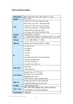
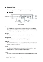
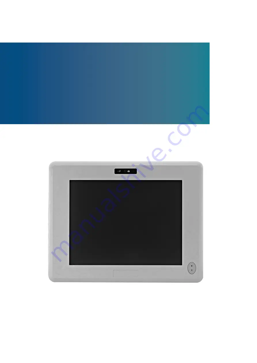
background image


KPC-1250 User’s Manual 


KPC-1250 

12.1”  Industrial Panel PC with Intel

®

 GM45 + ICH9-M


User’s Guide 


Summary of Contents for KPC-1250

Page 1: ...I KPC 1250 User s Manual KPC 1250 12 1 Industrial Panel PC with Intel GM45 ICH9 M User s Guide ...

Page 2: ...ademark of Quanmax All trademarks registered trademarks and trade names used in this user s guide are the property of their respective owners All rights reserved This user s guide contains information proprietary to Quanmax Customers may reprint and use this user s guide in other publications Customers may alter this user s guide and publish it only after they remove the Quanmax name cover and log...

Page 3: ...8 Unpacking 8 Regulatory Compliance Statements 8 Warranty Policy 9 Maintaining Your Computer 10 Chapter 1 Introduction 13 Overview 13 System tour 16 Mechanical Dimensions 18 Chapter 2 Getting Started 19 Setting up your PC 19 Turning on the System 21 VESA Mounting 22 Panel Mounting 23 Chapter 3 AMI BIOS Setup 25 Overview 25 Main Menu 26 Advanced Menu 28 Boot Menu 32 Chipset Menu 33 Power Menu 35 Se...

Page 4: ...ount Cut Out Hole and Maximum Panel Thickness 23 Figure 10 Panel Mounting 24 Tables Table 1 KPC 1250 product specifications 14 Table 2 BIOS Main Menu 26 Table 3 IDE Device Setting Menu 26 Table 4 System Information 27 Table 5 Advanced Menu 28 Table 6 Onboard Peripherals Configuration Settings 29 Table 7 On Chip ATA Configuration 30 Table 8 Hardware Health Configuration 31 Table 9 Boot Menu 32 Tabl...

Page 5: ...aution when installing or removing components Refer to the installation instructions in this user s guide for precautions and procedures If you have any questions please contact Quanmax Post Sales Technical Support Access can only be gained by service persons or by users who have been instructed about the reasons for the restrictions applied to the location and about any precautions that shall be ...

Page 6: ...ble itself Some cables have a connector with locking tabs If you are disconnecting this type of cable press in on the locking tabs before disconnecting the cable As you pull connectors apart keep them evenly aligned to avoid bending any connector pins Also before connecting a cable make sure both connectors are correctly oriented and aligned CAUTION Do not attempt to service the system yourself ex...

Page 7: ...d a board by its edges or by its metal mounting bracket Do not handle or store system boards near strong electrostatic electromagnetic magnetic or radioactive fields Instructions for Lithium Battery WARNING Danger of explosion when battery is replaced with incorrect type Only replace with the same or equivalent type recommended by the manufacturer Do not dispose of lithium batteries in domestic wa...

Page 8: ...r service immediately Refer to Warranty Policy for the return procedure Regulatory Compliance Statements This section provides the FCC compliance statement for Class A devices FCC Compliance Statement This equipment has been tested and found to comply with limits for a Class A digital device pursuant to Part 15 of the FCC rules These limits are designed to provide reason able protection against ha...

Page 9: ...ranty policy can be found under Support at www quanmax com Please consult your distributor for warranty verification The limited warranty is void if the product has been subjected to alteration neglect misuse or abuse if any repairs have been attempted by anyone other than Quanmax or its authorized agent or if the failure is caused by accident acts of God or other causes beyond the control of Quan...

Page 10: ...compliance with this Limited Warranty Return Policy will not be accepted by Quanmax Limitation of Liability In no event shall Quanmax be liable for any defect in hardware software loss or inadequacy of data of any kind or for any direct indirect incidental or consequential damages in connection with or arising out of the performance or use of any product furnished hereunder Quanmax s liability sha...

Page 11: ... pressure reduces the efficiency of the cooling fans to cool the system This can cause electrical problems related to arcing and corona effects This condition can also cause sealed components with internal pressure such as electrolytic capacitors to fail or perform at reduced efficiency Power Protection The greatest threats to a system s supply of power are power loss power spikes and power surges...

Page 12: ...g when AC power is lost The battery is charged by the AC power while it is available so when AC power is lost the battery can provide power to the system for a limited amount of time depending on the UPS system UPS systems range in price from a few hundred dollars to several thousand dollars with the more expensive unit s allowing you to run larger systems for a longer period of time when AC power...

Page 13: ... customer requirements The KPC series provide a compact high performance human machine interface with optimal shock vibration and temperature resistance for tough industrial demands Checklist KPC 1250 Power Adapter Power Cord Driver CD Quick installation Guide Features 12 1 TFT LCD Display 12 1 TFT LCD Display with Resistive 5 wire TouchScreen CPU Support Intel Core 2 Duo Processor T9400 6M Cache ...

Page 14: ... GB Storage 1 x 2 5 SATA HDD or 1 x SSD Material Aluminum front bezel SECC chassis IO 2x GbE RJ 45 4x USB 2 0 1x HDMI 1x DVI D 1x VGA 2x COMs with 5V 12V Power Selection 1x Power On Off Switch 1x Power Connector Line Out Line In Mic In Expansion 1xPCI Slot 1xMini PCIe slot LCD Display Display Type 12 TFT LCD Resolution XGA 1024x768 Brightness 500 cd m Touch Screen 5 wire Resistive Type Network Wir...

Page 15: ...User s Manual Humidity 0 C to 60 C CF SSD 0 C to 50 C 2 5 HDD Storage 0 C to 85 C 10 85 rel hum non condensing Mounting VESA Panel Mount Certifications CE FCC Class A IP65 front bezel Table 1 KPC 1250 product specifications ...

Page 16: ...ays use the supplied power adapter PCI Slot The PCI slot enables user to insert one add on card for expansion Power Switch The power button allows powering ON and OFF the system Audio Out The stereo headphone jack is used to connect the system s audio out signal to amplified speakers or headphones MIC IN The microphone jack is designed to connect the microphone used for video conferencing voice na...

Page 17: ...usly on a single computer with some peripheral acting as additional plug in sites or hubs Ethernet The eight pin RJ 45 LAN port supports a standard Ethernet cable for connection to a local network HDMI HDMI connector for display output DVI I DVI I connector for DVI D or VGA output VGA D Sub 15 pin VGA connector for display output COM D Sub 9 pin connector for RS 232 connection Side View Figure 2 S...

Page 18: ...Chapter 1 18 KPC 1250 User s Manual Mechanical Dimensions KPC 1250 Dimension 343 x 269 x 64 8 mm W x H x D Figure 3 Mechanical Dimensions of KPC 1250 ...

Page 19: ...ing the monitor Connect the appropriate cable from your display to the VGA DVI I HDMI port Figure 4 Connecting the display cable NOTE When the system reboots without connecting the VGA DVI I HDMI there might be no image on screen when you insert these cables Please pressing Ctrl Alt F4 simultaneously to show the image on screen ...

Page 20: ...our computer Figure 5 Connecting USB mouse keyboard NOTE Using a third party USB mouse or keyboard may require software drivers Check the manufacturer s website for the latest software drivers Connecting to a network device Connect one end of a network cable to the LAN port on the system rear panel and the other end to a hub or switch Figure 6 Network cable with RJ45 connector ...

Page 21: ... 1 Connect the power adapter cable to the DC jack DC IN of the KPC 1250 2 Connect the power cable to the power adapter 3 Connect the power cable to a power outlet 4 Press the power switch on the front panel to turn on the system Figure 7 Turing on the System ...

Page 22: ...0 User s Manual VESA Mounting The product comes with VESA FDMI 75 100 standard mounting holes as shown below Use 4 screws with the appropriate length for your mounting bracket Figure 8 VESA Mounting Hole Locations KPC 1250 ...

Page 23: ...el Mounting The Panel PC can be panel mounted and comes with brackets and screws for this purpose The required cutout for panel mounting and maximum panel thickness is shown below Figure 9 Panel Mount Cut out hole and maximum panel thickness ...

Page 24: ...Chapter 2 24 KPC 1250 User s Manual Below are the demonstrations of how to do panel mounting Step1 Tightening the screws as shown right Step2 Done Figure 10 Panel Mounting ...

Page 25: ...ase contact with your dealer AMI s ROM BIOS provides a built in Setup program which allows the user to modify the basic system configuration and hardware parameters The modified data will be stored in a battery backed CMOS so that data will be retained even when the power is turned off In general the information saved in the CMOS RAM will not need to be changed unless there is a configuration chan...

Page 26: ... 2010 System Time 14 05 06 SATA 1 Not Detected SATA 2 Not Detected SATA 3 Not Detected CF Not Detected System Information Å Select Screen Select Item Change Field Tab Select Field F1 General Help F10 Save and Exit ESC Exit V02 67 C Copyright 1985 2006 American Megatrends Inc Table 3 IDE Device Setting Menu BIOS SETUP UTILITY M a i n A d v a n c e d B o o t C h i p s e t P o w e r S e c u r i t y E...

Page 27: ...ng Analysis and Reporting Technology It allows AMIBIOS to use the SMART protocol to report server system information over a network Options Auto Disabled Enabled Table 4 System Information BIOS SETUP UTILITY M a i n A d v a n c e d B o o t C h i p s e t P o w e r S e c u r i t y E x i t AMIBIOS Version 2 41 Build Date 12 20 10 Processor Genuine Intel CPU 575 2 00 GHz Speed 2000MHz Physical Memory ...

Page 28: ...Address 378 Parallel Port Mode Normal Parallel Port IRQ IRQ7 Allows BIOS to Select Serial Port1 Base Addresses Å Select Screen Select Item Change Option F1 General Help F10 Save and Exit ESC Exit V02 67 C Copyright 1985 2006 American Megatrends Inc Press Enter to select a sub menu for detailed options COM1 Address Options Disabled 3F8 3E8 2E8 COM1 IRQ Options 3 4 10 11 COM1 Function Type Options R...

Page 29: ...Board Peripherals Configuration Settings USB Functions 12 USB Ports USB 2 0 Controller Enabled Legacy USB Support Enabled Audio Controller Enabled Onboard LAN1 Controller Enabled Onboard LAN2 Controller Enabled Onboard LAN OPTROM Disabled Onboard Mini PCIE Controller Enabled On Chip ATA Devices Options Disabled 2 USB Ports 4 USB Ports 6 USB Ports 8 USB Ports 10 USB Ports 12 USB Ports Å Select Scre...

Page 30: ...able 7 On Chip ATA Configuration BIOS SETUP UTILITY M a i n A d v a n c e d B o o t C h i p s e t P o w e r S e c u r i t y E x i t On Chip ATA Configuration SATA Configuration Enhanced Configure SATA as IDE Options Disabled Compatible Enhanced Å Select Screen Select Item Change Option F1 General Help F10 Save and Exit ESC Exit V02 67 C Copyright 1985 2006 American Megatrends Inc On Chip ATA Confi...

Page 31: ... F System Temperature 44 C 111 F CPU Fan Speed 7105 RPM SYS Fan Speed N A VCORE 1 176 V 3 3V 3 408 V 5V 5 130 V Input 11 868 V Options Disabled 80 C 176 F 85 C 185 F 90 C 194 F 95 C 203 F Å Select Screen Select Item Change Option F1 General Help F10 Save and Exit ESC Exit V02 67 C Copyright 1985 2006 American Megatrends Inc CPU Warning Temperature Options Disabled 80 C 176 F 85 C 185 F 90 C 194 F ...

Page 32: ...Exit V02 67 C Copyright 1985 2006 American Megatrends Inc Quick Boot Enabling this item allows BIOS to skip some Power On Self Tests POST while booting to decrease the time needed to boot the system When set to Disabled BIOS performs all the POST items Options Disabled Enabled Full Screen LOGO Display Options Disabled Enabled Bootup Num Lock On Allow you to select the power on state for the NumLoc...

Page 33: ...Video Function Configuration Select which graphics controller to use as the primary boot device Å Select Screen Select Item Change Option F1 General Help F10 Save and Exit ESC Exit V02 67 C Copyright 1985 2006 American Megatrends Inc Boots Graphic Adapter Priority Options IGD PCI IGD PCI PEG PEG IGD PEG PCI Internal Graphics Mode Select Select the amount of system memory used by the Internal graph...

Page 34: ... LVDS Panel Type 1024x768 18Bi Panel BackLight Voltage V 2 5 Options DVMT Mode Å Select Screen Select Item Change Option F1 General Help F10 Save and Exit ESC Exit V02 67 C Copyright 1985 2006 American Megatrends Inc DVMT Mode Select Options DVMT Mode only DVMT FIXED Memory Options 128MB 256MB Maximum DVMT Boot Display Device Options CRT DVI CRT DVI LVDS CRT LVDS Panel Type Options 1024x768 24Bit ...

Page 35: ...NABLE If OS supports ACPI DISABLE If OS does not support ACPI Å Select Screen Select Item Change Option F1 General Help F10 Save and Exit ESC Exit V02 67 C Copyright 1985 2006 American Megatrends Inc ACPI Function Enable Disable ACPI support for Operating System ENABLE If OS supports ACPI DISABLE IF OS Does not support ACPI Suspend mode Options S1 POS S3 STR Repost Video on S3 Resume Determines wh...

Page 36: ...the password Å Select Screen Select Item Enter Change F1 General Help F10 Save and Exit ESC Exit V02 67 C Copyright 1985 2006 American Megatrends Inc Change Supervisor Password Select this item to set or change the supervisor password The Supervisor Password item on top of the screen displays the default Not Installed After you have set a password this item displays Installed Change User Password ...

Page 37: ...ved to the CMOS RAM The CMOS RAM is sustained by an onboard backup battery and stays on even when the PC is turned off When you select this option a confirmation window appears Select Yes to save changes and exit Discard Changes and Exit Exit system setup without saving any changes Select this option only if you do not want to save the changes that you made to the Setup program If you made changes...

Page 38: ...ce settings for your system The F9 key can be used for this operation Load Failsafe Defaults Load Optimal Default values for all the setup values This option allows you to load failsafe default values for each of the parameters on the Setup menus which will provide the most stable performance settings The F8 key can be used for this operation ...

Page 39: ... and the necessary drivers to operate it After you have finished assembling your system and connected the appropriate power source power it up using the power supply and install the desired operating system You can download the drivers for the KPC 1250 from the Quanmax website at 51Hwww quanmax com and install as instructed there For other operating systems please contact Quanmax ...

Reviews: