background image

 

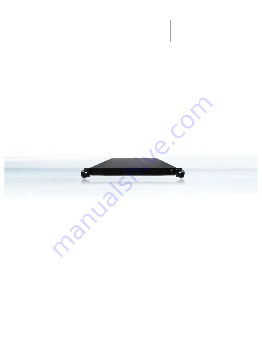
USER GUIDE


RAK-120S  

Doc. User Guide, Rev. 1.0  

Doc. ID: [To be Determined]  


Summary of Contents for RAK-120S

Page 1: ...USER GUIDE RAK 120S Doc User Guide Rev 1 0 Doc ID To be Determined...

Page 2: ...RAK 120S User Guide Rev 1 0 2 This page has been intentionally left blank...

Page 3: ...esentation or warranty that such application will be suitable for the specified use without further testing or modification We expressly inform the user that this user guide only contains a general de...

Page 4: ...at your risk To minimize the risks associated with your products and applications you should provide adequate design and operating safeguards You are solely responsible for compliance with all legal...

Page 5: ...Service As a trusted technology innovator and global solutions provider we extend our embedded market strengths into a services portfolio allowing companies to break the barriers of traditional produ...

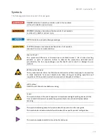
Page 6: ...the law may endanger your life health and or result in damage to your material ESD Sensitive Device This symbol and title inform that the electronic boards and their components are sensitive to stati...

Page 7: ...work on this product Earth ground connection to vehicle s chassis or a central grounding point shall remain connected The earth ground cable shall be the last cable to be disconnected or the first ca...

Page 8: ...is necessary to store or ship the product then re pack it in the same manner as it was delivered Special care is necessary when handling or unpacking the product See Special Handling and Unpacking In...

Page 9: ...17 2 2 FCC Statement USA 17 2 3 EMC Compliance Canada 17 3 Shipment and Unpacking 18 3 1 Unpacking 18 3 2 Scope of Delivery 18 3 2 1 Standard 18 3 2 2 Optional Parts 18 4 System Overview 19 4 1 System...

Page 10: ...onnection 37 8 Start Up 38 8 1 Connecting to DC Power Supply 38 8 2 Operating System and Hardware Component Drivers 39 9 Maintenance and Cleaning 40 10 Technical Specifications 41 10 1 Mechanical Spec...

Page 11: ...l Drawing 42 Figure 16 BIOS Main Menu Screen System Data and Time 48 Figure 17 BIOS Advanced Menu 50 Figure 18 BIOS Advanced Menu FIA HSIO12 Configuration 51 Figure 19 BIOS Advanced Menu CPU Chipset C...

Page 12: ...RAK 120S User Guide Rev 1 0 12...

Page 13: ...ent air circulation is available to cool the product please ensure that the ventilation openings are not covered or blocked If an air filter is provided this should be cleaned regularly Do not place t...

Page 14: ...a reliable protective earthing connection is provided a suitable easily accessible disconnecting device is used in the application e g overcurrent protective device if the device itself is not discon...

Page 15: ...uctive materials such as ordinary plastic assembly aids and Styrofoam 7 Use only field service tools which are conductive such as cutters screwdrivers and vacuum cleaners 8 Always place drives and boa...

Page 16: ...Do not dispose of lithium batteries in general trash collection Dispose of the battery according to the local regulations dealing with the disposal of these special materials e g to the collecting po...

Page 17: ...nd used in accordance with the instructions may cause harmful interference to radio communications However there is no guarantee that interference will not occur in a particular installation If this e...

Page 18: ...g damage 6 If you notice any shipping damage or inconsistencies between the contents and your order please contact us for help and information 3 2 Scope of Delivery 3 2 1 Standard 1x RAK 120S correspo...

Page 19: ...PCIe x16 Card Slot x8 signal 3x Antenna Port 1x AC Power Socket Standard Baseboard and System Expansion Capabilities 2x DDR4 UDIMM memory socket DIMM1 DIMM2 4x SATA 3 0 data socket any four among SATA...

Page 20: ...ia mSATA mPCIe Interface The baseboard comes with an onboard full sized mSATA mPCIe interface connector The connector can be switched to mSATA or mPCIe setting via the jumper JP1 Users can expand the...

Page 21: ...age on the baseboard The unit is only completely disconnected from the DC mains when the power is removed 4 2 2 Power LED The power LED lights up green if the system powered on Prerequisite The system...

Page 22: ...t respectively 4 3 2 VGA An external analog monitor can be plugged into this interface The VGA port is provided as a 15 pin D SUB socket VGA Hot Plug works on Windows and Linux installation which have...

Page 23: ...nal PCIe x16 Add on card slot for network storage graphics video or other functional expansion The slot supports only x8 signal There are two accessible bays on the rear I O panel Only the upper one c...

Page 24: ...2 4 M 2 Key B Socket M2B1 see Chapter 4 4 3 5 mSATA mPCIe Socket MPCIE1 see Chapter 4 4 4 6 PCIe x16 Add on Card Slot PCIE1 see Chapter 4 4 5 7 Dual 2 5 HDD SSD bracket see Chapter 4 4 2 8 M 2 fixing...

Page 25: ...zed mPCIe WLAN WLAN Bluetooth card The switch between mSATA and mPCIe can be configured via jumper JP1 In case of installing an mPCIe WWAN modem card an additional SIM card cage is required it must be...

Page 26: ...Only personnel with appropriate qualifications trainings and authorization are permitted to install and work with the device The installation removal of HHD SSD and or expansion cards may only be perf...

Page 27: ...orm the following steps 1 Close all applications Shut down the system properly and disconnect the connection to the main power source Disconnect all peripherals 2 The RAK 120S should lay on a flat cle...

Page 28: ...osed and correctly engaged with the notch on the memory module edge 7 Repeat step 2 6 to install the second UDIMM memory module in case two DIMM memory modules are required Use memory modules with the...

Page 29: ...ction 5 1 Opening and Closing the Chassis 5 1 4 Installing an mSATA SSD mPCIe expansion Card To install an mSATA SSD mPCIe expansion card please proceed according to the steps described 1 Open the dev...

Page 30: ...mum of airflow through and around the box proper distances to surrounding parts must be observed 6 4 Maximum Temperatures The maximum system ambient temperature depends mostly on the power consumption...

Page 31: ...red with third party components like mPCIe M 2 expansion card s and hard drives HDD or SSD it has to be taken into account that the air temperature inside the system is higher than the ambient tempera...

Page 32: ...operated only by trained and qualified personnel Only personnel with appropriate qualifications trainings and authorization are permitted to install and work with the RAK 120S This device shall only b...

Page 33: ...of M5 screws for ear plate fastening and two pieces of M4 screws for chassis fastening Each slide is composed of a chassis inner slide rail and a cabinet outer slide rail Figure 8 Optional rackmount s...

Page 34: ...hassis 3 Release the safety lock to unlock position before mounting the cabinet slide rail Insert the stag into the upper and lower square holes on EIA rack rail from the back of rack rail Push the sa...

Page 35: ...e to the server chassis if ball retainer is not in fully open position while mounting the server 5 Release the slide from locking position by pressing the trigger down Then Push the server back to the...

Page 36: ...erver For a sufficient air circulation around the device we recommend keep a proper clearance and not mount operate any other devices within the clearance around the RAK 120S Cabinet rack rail Center...

Page 37: ...120S User Guide Rev 1 0 37 7 2 AC Power Connection The RAK 120S integrates a power supply unit with the chassis and can be connected by a AC in power socket Figure 2 pos 1 directly to an AC power sou...

Page 38: ...restrict access to power cable disconnection must be guaranteed using a separate cut off fixture Ensure that the mains power supply socket power outlet is properly grounded and the power cable is in...

Page 39: ...onents Your system is fully operational when you switch it on for the first time If you have ordered the RAK 120S without a pre installed operating system you will need to install the operating system...

Page 40: ...peration For light soiling clean the RAK 120S with a dry cloth Carefully remove dust from the surface of the chassis using a clean soft brush Stubborn dirt should be removed using a mild detergent and...

Page 41: ...to 4x 2 5 SATA 3 0 HDD SSD 1x M 2 Key B type 2280 for SSD only 1x mPCIe mSATA full size mixed with SATA 3 0 USB 2 0 1x PCIe x16 x8 signal support 1x Micro SIM Card Cage by cable optional Power Input V...

Page 42: ...Construction 1U Metal Rackmount Chassis Dimensions W x D x H 430 4 mm x 400 0 mm x 44 5 mm 16 94 x 15 75 x 1 75 without handles 480 5 mm x 439 0 mm x 44 5 mm 18 92 x 17 28 x 1 75 with handles Weight 5...

Page 43: ...3 3 2013 and IEC 61000 3 3 2013 EN 55024 2010 A1 2015 and CISPR 24 2010 A1 2015 EN 61000 4 2 2009 and IEC 61000 4 2 2008 EN 61000 4 3 2006 A1 2008 A2 2010 and IEC 61000 4 3 2006 A1 2007 A2 2010 EN 610...

Page 44: ...thernet Connector Table 7 Ethernet Connector see Figure 2 pos 3 Pin Signal Name LAN1 LAN6 RJ45 1 MDI 0 8 7 6 5 4 3 2 1 2 MDI 0 3 MDI 1 4 MDI 1 5 MDI 2 6 MDI 2 7 MDI 3 8 MDI 3 11 3 USB 3 0 Port Table 8...

Page 45: ...2 Green 3 Blue 4 NC 5 GND 6 GND 7 GND 8 GND 9 VCC 10 GND 11 NC 12 DDC data 13 HSYNC 14 VSYNC 15 DDC Clock 11 6 RS232 422 485 Serial Port Table 11 RS232 422 485 Serial Port see Figure 2 pos 5 Pin RS232...

Page 46: ...otected a request for password will appear Enter either the User Password or the Supervisor Password see Security menu press RETURN and proceed with step 5 5 A setup menu will appear The RAK 120S uEFI...

Page 47: ...fic Help window providing an explanation of the respective function 12 2 1 Main Setup Menu Upon entering the uEFI BIOS Setup program the Main Setup menu is displayed This screen lists the Main Setup m...

Page 48: ...n 24h Processor Cores 4 4 Select Screen Memory Information Select Item Total Size 8192 MB DDR4 Enter Select Frequency 2133 MHz Change Opt F1 General Help System Date Fri 08 30 2019 F2 Previous Values...

Page 49: ...creen functions are included in the menu LAN Configuration FIA HSIO12 Configuration CPU Chipset Configuration NVMe Configuration SATA Configuration USB Configuration Trusted Computing Network Stack Co...

Page 50: ...Configuration Change Opt Trusted Computing F1 General Help Network Stack Configuration F2 Previous Values Super IO Configuration F3 Optimized Defaults Serial Port Console Redirection F4 Save Exit H W...

Page 51: ...t Version 2 19 1266 Copyright C 2019 American Megatrends Inc Feature Option Description Lane 8 PCIE C6139 VGA Lane Disabled PCIE Enable Select Lane to work as Disabled PCIE C6139 VGA Lane18 XHCI Lane...

Page 52: ...bled SATA Enable Select Lane to work as Disabled SATA5 Lane17 SATA6 Lane Disabled SATA Enable Select Lane to work as Disabled SATA6 mPCIE1 W DISABLE Pin Disabled Driven Low Enabled Driven High Control...

Page 53: ...ether to enable or disable CPU Turbo capability CPU C State Disabled Enabled Select whether to enable or disable the Enhanced Cx state of the CPU VMX Disabled Enabled Select whether to enable or disab...

Page 54: ...ITY Main Advanced Power Boot Security Save Exit NVMe controller and Drive information No NVMe Device Found Select Screen Select Item Enter Select Change Opt F1 General Help F2 Previous Values F3 Optim...

Page 55: ...Multiplier Enabled Disabled Select whether to enable or disable SATA Controller 0 port multiplier support in CAP register of the controller SATA Controller 1 Enabled Disabled Select whether to enable...

Page 56: ...e Exit ESC Exit Version 2 19 1266 Copyright C 2019 American Megatrends Inc Feature Option Description Legacy USB Support Enabled Disabled Auto Select whether to enable or disable Legacy USB support AU...

Page 57: ...ct Screen Select Item Enter Select Change Opt F1 General Help F2 Previous Values F3 Optimized Defaults F4 Save Exit ESC Exit Version 2 19 1266 Copyright C 2019 American Megatrends Inc Feature Option D...

Page 58: ...etwork Protocol Intel I210 AT 2 LAN Boot X553 1GbE 1 Disabled Load PXE Select whether to enable or disable load onboard PXE Preboot Execution Environment or uEFI SNP Simple Network Protocol Intel X553...

Page 59: ...per Port 1 Configuration Serial Port Enabled Select Screen Device Settings IO 3F8h IRQ 4 Select Item Enter Select Change Setting Auto Change Opt Serial Port 1 Type RS232 F1 General Help RS485 Deplux M...

Page 60: ...al Help RS485 Deplux Mode Half Duplex F2 Previous Values RS485 Auto Flow Control Disabled F3 Optimized Defaults F4 Save Exit ESC Exit Version 2 19 1266 Copyright C 2019 American Megatrends Inc These i...

Page 61: ...elect Item Enter Select Legacy Console Redirection Change Opt Legacy Console Redirection Settings F1 General Help F2 Previous Values Serial Port for Out of Band Management Windows Emergency Management...

Page 62: ...0 115200 Select serial port transmission speed The speed must be matched on the other side Long or noisy lines may require lower speeds Data Bits 7 8 Select data bits Parity None Even Odd Mark Space A...

Page 63: ...3 Feature Option Description Terminal data Resolution 100x31 Disabled Enabled Select whether to enable or disable extended terminal resolution Putty KeyPad VT100 LINUX XTERMR6 SCO ESCN VT400 Select Fu...

Page 64: ...0 115200 Select serial port transmission speed The speed must be matched on the other side Long or noisy lines may require lower speeds Data Bits 7 8 Select data bits Parity None Even Odd Mark Space A...

Page 65: ...5 Feature Option Description Terminal data Resolution 100x31 Disabled Enabled Select whether to enable or disable extended terminal resolution Putty KeyPad VT100 LINUX XTERMR6 SCO ESCN VT400 Select Fu...

Page 66: ...ous Values F3 Optimized Defaults F4 Save Exit ESC Exit Version 2 19 1266 Copyright C 2019 American Megatrends Inc Feature Option Description Redirection COM Port COM1 COM2 Select a COM port to display...

Page 67: ...menu Feature Option Description Out of Band Mgmt Port COM1 COM2 Microsoft Windows Emergency Management Services EMS allows for remote management of a Windows Server OS through a serial port Terminal...

Page 68: ...DTS 34 C CPU Temperature Therm 34 C System Temperature 36 C CPU Fan Speed 1412 RPM Select Screen SYS Fan Speed N A Select Item Enter Select VCORE 1 029 V Change Opt 12V 12 892 V F1 General Help 5V 4...

Page 69: ...wer Off Power On Last State Select AC power state when power is re applied after a power failure Select Power Off if you want the system to remain off after power restored Select Power On if you use a...

Page 70: ...Timer Configuration BIOS SETUP UTILITY Main Advanced Power Boot Security Save Exit WatchDog Timer Configuration WDT Function Disabled Select Screen WDT Count Mode Minute Select Item WDT Timer 3 Enter...

Page 71: ...right C 2019 American Megatrends Inc These items appear only when selecting UEFI and Legacy or UEFI only Feature Option Description Full Screen LOGO Display Disabled Enabled Select whether to enable o...

Page 72: ...ecurity Save Exit Boot Option 1 P4 WDC WD3200LPCX Boot Option 2 P5 WDC WD3200LPCX Select Screen Select Item Enter Select Change Opt F1 General Help F2 Previous Values F3 Optimized Defaults F4 Save Exi...

Page 73: ...is set then this is a power on password and must be entered to boot or enter Setup In Setup the User will have Administrator rights The password length must be in the following range Minimum Length 3...

Page 74: ...all passwords in a safe place Forgotten passwords results in being locked out of the system If the system cannot be booted because the User Password or the Supervisor Password are not know contact ou...

Page 75: ...ption a confirmation window appears Select Yes to save changes and exit Discard Changes and Exit Exit system setup without saving any changes Select this option only if you do not want to save the cha...

Page 76: ...High Definition Multimedia Interface LAN Local Area Network LED Light Emitting Device LVDS Low Voltage Differential Signaling ME F W Management Engine Firmware mPCIe mini Peripheral Component Intercon...

Page 77: ...RAK 120S User Guide Rev 1 0 77...

Reviews: