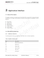
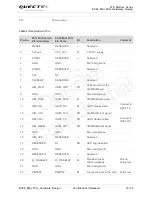
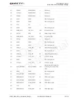
Quectel EC20, Hardware Manual
The Cantherm EC20 user manual is available for free download on our website. This manual provides detailed instructions on how to properly operate and maintain your Cantherm EC20 device. Ensure you have the necessary knowledge to get the most out of your product by downloading the manual today from 88.208.23.73:8080.
Share
Download


Reviews:
No comments
Related manuals for EC20

DUB-1310
Brand: D-Link Pages: 2

DWL-500
Brand: D-Link Pages: 6

AirPro DWL-A520
Brand: D-Link Pages: 8

AirPro DWL-A520
Brand: D-Link Pages: 63

T1
Brand: Xilinx Pages: 48

Express5800/320Ma
Brand: NEC Pages: 74

AirConnect
Brand: 3Com Pages: 14

ACS-61100
Brand: Accusys Pages: 2

Lagoon
Brand: M-Audio Pages: 28

1212M
Brand: E-Mu Pages: 108

XEVA200
Brand: hager Pages: 6

Gigabit Network Set
Brand: Hama Pages: 6

10/100 EtherJet
Brand: IBM Pages: 64

PCI-P16C16
Brand: ICP DAS USA Pages: 6

5710
Brand: IBM Pages: 52

PCISA-9652
Brand: IEI Technology Pages: 12

HDC-301MS-R10
Brand: IEI Technology Pages: 40
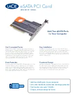
eSATA PCI Card
Brand: LaCie Pages: 2


