background image

Puma 20 / 40

TECHNICAL MANUAL

EN

Powered wheelchair

Summary of Contents for puma 20

Page 1: ...Puma 20 40 TECHNICAL MANUAL EN Powered wheelchair ...

Page 2: ...Puma 20 40 2 ...

Page 3: ...n provided is valid for the product in its standard version Sunrise Medical can therefore not be held liable for any damage resulting from specifications of the product deviating from the standard configuration Illustrations contained in the manual may deviate from the configuration of your product The information made available has been prepared with all possible diligence but Sunrise Medical can...

Page 4: ... forks and wheels Puma 40 3 spoke wheels October 2016 24 10 Castor forks and wheels Puma 40 November 2016 25 11 Castor forks and wheels Puma 20 all versions 27 12 Covers Puma 40 5 spoke wheels October 2016 29 13 Covers Puma 40 3 spoke wheels October 2016 30 14 Covers Puma 40 November 2016 31 15 Covers Puma 20 October 2016 32 16 Covers Puma 20 November 2016 33 17 Tilt and lift modules Puma 40 all v...

Page 5: ... Puma versions 139 5 3 21 Mounting the attendant Z steering mechanisme Sedeo Pro only for Norwegian market 140 5 3 22 Replacing the batteries all Puma versions 141 5 3 23 Replacing the power module all Puma versions 145 5 3 24 Replacing the mudguards Puma 40 5 spoke wheels October 2016 147 5 3 25 Replacing the mudguards Puma 40 3 spoke wheels October 2016 149 5 3 26 Replacing the mudguards Puma 20...

Page 6: ...eelchair User manual Service manual Service and technical support For information concerning specific settings maintenance or repair works please contact your supplier He is always prepared to help you Ensure you have at hand Model Year of manufacture Identification number This information is provided on the identification plate See Identification of the product 1 2 Identification of the product T...

Page 7: ...terference precautions Precautions in combining seat adjustment settings When fitting and optimizing different seating settings and functions professionals should be aware that not all settings can be combined over the full range There are limitations to take into account when using electrical tilt although unlikely in average fitting situations Combining extremer settings can cause the back of th...

Page 8: ...it cannot be excluded that electromagnetic radiation may have an influence on the wheelchair For example mobile telephony large scale medical apparatus other sources of electromagnetic radiation it cannot be excluded that the wheelchair may interfere with electromagnetic fields For example shop doors burglar alarm systems in shops garage door openers In the unlikely event that such problems do occ...

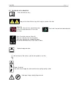
Page 9: ...ards downwards Don t put the freewheel switch in Push mode on a slope Battery charging connection Attachment point of the tie down system for transportation in a vehicle Danger of crushing Use caution when swinging the controller aside to avoid getting anything crushed Trap danger Danger of getting fingers jammed right hand Drive mode freewheel lever inwards upwards Puma 40 Push mode freewheel lev...

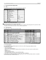
Page 10: ...mming cable GSM61171 X X X X Dynamic 1003236 Dynamic Wizard USB set DWIZ KIT DWD OEM U X X X X Dynamic 9006857 R net Diagnostic Test Tool D50996 X X PGDrivesTechnology 9006858 R net Programming cable for R net DTT SA79174 X X PGDrivesTechnology PR0111 Pilot Hand Held Programmer PP1B D49511 X X X PGDrivesTechnology 9006859 VR 2 Programming cable for R net DTT SA79176 X X PGDrivesTechnology PR0200 P...

Page 11: ...he part concerned cannot be purchased separately The part concerned is part of the assembly shown This assembly must be ordered as one piece It has to be replaced in its entirety Boxed position numbers refer to the relevant drawing Order address Please mail or fax your orders to your supplier Service technicians Repairs may only be carried out by trained and authorised service technicians During t...

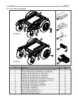
Page 12: ...uma 40 5 spoke wheels October 2016 22 9 Castor forks and wheels Puma 40 3 spoke wheels October 2016 24 10 Castor forks and wheels Puma 40 November 2016 25 11 Castor forks and wheels Puma 20 all versions 27 12 Covers Puma 40 5 spoke wheels October 2016 29 13 Covers Puma 40 3 spoke wheels October 2016 30 14 Covers Puma 40 November 2016 31 15 Covers Puma 20 October 2016 32 16 Covers Puma 20 November ...

Page 13: ...Puma 20 40 Spare parts 13 20 Direct access Puma 20 40 all versions 37 21 Attendant Z steering only for the Norwegian market 38 Pos Description Page Continued from Carrier and seat adjustments ...

Page 14: ... 7 4 9005958 Battery spacer set MK 60 74A 6 7 1 9005959 Battery spacer set Sonnenschein spacers needed if equiped with Sonnenschein Batteries not a standard Sunrise Medical item 8 9 1 9005931 Battery straps 8 13 1 9005930 Battery box 14a 2 1007078 Socket head screw DX2 14b 2 9006237 Socket head screw Shark 14c 2 00000 4042 Socket head screw R net 120 14d 2 00000 4035 Socket head screw R net 90 VR2...

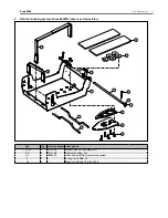
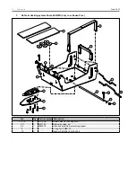
Page 15: ... 12 16 1 1017025 Battery Box Car Docking FWD 2 11 1 1017123 Dahl cardocking set 3 4 1 9009478 Plate and bolts Dahl cardocking system 9 1 O ring 7x2 5 NBR 70 10 1 Washer Pa Di Do 10 6 20 S 2 2 2 Dahl car docking system Puma 40 FWD only i c w Sedeo Pro 1 2 3 4 6 5 8 9 10 7 11 12 13 14 15 16 ...

Page 16: ...026 Battery Box Car Docking RWD 2 11 1 1017123 Dahl cardocking set 3 4 1 9009478 Plate and bolts Dahl cardocking system 9 1 O ring 7x2 5 NBR 70 10 1 Washer Pa Di Do 10 6 20 S 2 2 3 Dahl car docking system Puma 40 RWD only i c w Sedeo Pro 1 2 3 4 6 5 8 9 10 7 11 12 13 14 15 16 ...

Page 17: ...tor 4 pole RWD right FWD left 10 km h DX and Shark version October 2016 32 34 39 43a 44a 1 9011580 Motor 4 pole RWD left FWD right 10 km h PG R net and VR2 version October 2016 32 34 39 43b 44a 1 9011581 Motor 4 pole RWD right FWD left 10 km h PG R net and VR2 version October 2016 32 34 39 45a 44b 1 9011582 Motor 4 pole RWD left FWD right 12 5 km h DX and Shark version October 2016 32 34 39 45b 44...

Page 18: ... 10 km h DX and Shark version November 2016 Puma 40 35 39 42b 44a 1 9006788 Motor 4 pole RWD right FWD left 10 km h DX and Shark version November 2016 Puma 40 35 39 43a 44a 1 9006789 Motor 4 pole RWD left FWD right 10 km h PG R net and VR2 version November 2016 Puma 40 35 39 43b 44a 1 9006790 Motor 4 pole RWD right FWD left 10 km h PG R net and VR2 version November 2016 Puma 40 35 39 45a 44b 1 900...

Page 19: ...ticle number Description 39 2 9002784 Brake Release Sticker 44a 2 9005107 4PHT 8 mm motor brushes service 6 and 10 km h 44b 2 9008819 4PHT 5 mm motor brushes service 12 5 km h Continued from Suspension arm and motors Puma 40 November 2016 ...

Page 20: ...0 see paragraph 5 2 1 25 27 34b 37 38 1 9007483 Motor RWD left FWD right 6 km h PG R net and VR2 Puma 20 see paragraph 5 2 1 25 27 35 37 38 1 9007484 Motor set 10 km h DX and Shark Puma 20 25 27 35a 37 38 1 9007485 Motor RWD right FWD left 10 km h DX and Shark Puma 20 see paragraph 5 2 1 25 27 35b 37 38 1 9007486 Motor RWD left FWD right 10 km h DX and Shark Puma 20 see paragraph 5 2 1 25 27 36 37...

Page 21: ...r RWD left FWD right 6 km h PG R net and VR2 Puma 20 see paragraph 5 2 1 28 32 35 37 38 1 9007484 Motor set 10 km h DX and Shark Puma 20 28 32 35a 37 38 1 9007485 Motor RWD right FWD left 10 km h DX and Shark Puma 20 see paragraph 5 2 1 28 32 35b 37 38 1 9007486 Motor RWD left FWD right 10 km h DX and Shark Puma 20 see paragraph 5 2 1 28 32 36 37 38 1 9007487 Motor set 10 km h PG R net and VR2 Pum...

Page 22: ... mounting set Puma 40 5 spoke wheels version October 2016 22 31 2 9011634 Drive wheel indoor 12 1 2 x 2 1 4 12 5 air excl hub 23 31 2 9011635 Drive wheel indoor 12 1 2 x 2 1 4 12 5 punctureproof excl hub 24 31 2 9011636 Drive wheel outdoor 3 00 8 grey air 14 excl hub 25 31 2 9011637 Drive wheel outdoor 3 00 8 grey punctureproof 14 excl hub 26 31 2 9011638 Drive wheel outdoor 3 00 8 grey air 14 All...

Page 23: ...ion October 2016 17 21 28 29 31 1 9011601 Wheel Set outdoor 3 00 8 14 black PU version October 2016 2 9005933 Anti shimmy set 2 9008817 Anti shimmy set XT 12 5 km h 2 1015116 Inner tube 2 80 2 50x4 9 2 1015107 Outer tyre 2 80 2 50x4 9 grey line profile 2 1015115 Inner tube 3 00 4 10 2 1015105 Outer tyre 3 00 4 10 grey highway profile 2 1015106 Outer tyre 3 00 4 10 black highway profile 2 1015118 I...

Page 24: ...of set 20 21 2 9011616 Drive wheel mounting set Puma 40 3 spoke wheels version October 2016 22 2 9011617 Drive wheel outdoor 3 00 8 14 black black air 22 1 9011618 Drive wheel outdoor 3 00 8 14 black black air set 23 2 9011619 Drive wheel outdoor 3 00 8 14 black black punctureproof 23 1 9011620 Drive wheel outdoor 3 00 8 14 black black punctureproof set 18 19 30 2 9011621 Wheel Mount hub assy 3 Sp...

Page 25: ...ng set Puma 40 version November 2016 22 31 2 9011634 Drive wheel indoor 12 1 2 x 2 1 4 air 12 5 excl hub 23 31 2 9011635 Drive wheel indoor 12 1 2 x 2 1 4 punctureproof 12 5 excl hub 24 31 2 9011636 Drive wheel outdoor 3 00 8 grey air 14 excl hub 25 31 2 9011637 Drive wheel outdoor 3 00 8 grey punctureproof 14 excl hub 26 31 2 9011638 Drive wheel outdoor 3 00 8 grey air 14 All Weather excl hub 27 ...

Page 26: ...elcover grey 2 9005933 Anti shimmy set 2 9008817 Anti shimmy set XT 12 5 km h 2 1015116 Inner tube 2 80 2 50x4 9 2 1015107 Outer tyre 2 80 2 50x4 9 grey line profile 2 1015115 Inner tube 3 00 4 10 2 1015105 Outer tyre 3 00 4 10 grey highway profile 2 1015106 Outer tyre 3 00 4 10 black highway profile 2 1015118 Inner tube 12 1 2 x 2 1 4 12 5 2 1015112 Outer tyre 12 1 2 x 2 1 4 12 5 grey block profi...

Page 27: ...nctureproof excl hub 16 19 2 9011636 Drive wheel outdoor 3 00 8 grey air 14 excl hub 16 19 2 9011637 Drive wheel outdoor 3 00 8 grey punctureproof 14 excl hub 16 19 2 9011638 Drive wheel outdoor 3 00 8 grey air 14 All Weather excl hub 16 19 2 9011639 Drive wheel outdoor 3 00 8 black air 14 excl hub 16 19 2 9011640 Drive wheel outdoor 3 00 8 black punctureproof 14 excl hub 18a 2 9011642 Hub indoor ...

Page 28: ... 1015107 Outer tyre 2 80 2 50x4 9 grey line profile 2 1015115 Inner tube 3 00 4 10 2 1015105 Outer tyre 3 00 4 10 grey highway profile 2 1015118 Inner tube 12 1 2 x 2 1 4 12 5 2 1015112 Outer tyre 12 1 2 x 2 1 4 12 5 grey block profile 2 1015117 Inner tube 3 00 8 14 2 1015111 Outer tyre 3 00 8 14 grey block profile Continued from Castor forks and wheels Puma 20 all versions ...

Page 29: ...ss cover 10 13 2 9011606 Drive wheel fender black with bracket set version October 2016 11 12 1 9011607 Drive wheel fender bracket set version October 2016 14 2 1007448 PVC black cover M10 DIN 912 15 1 9011608 Motor Arm Covers black set version October 2016 17 20 1 9011605 Tube bottom cover set version October 2016 18e 1 9011604 Ballhead covers black set 21 22 2 9005976 Castor wheel fender black 2...

Page 30: ...ss cover 10 13 2 9011606 Drive wheel fender black with bracket set version October 2016 11 12 1 9011607 Drive wheel fender bracket set version October 2016 14 2 1007448 PVC black cover M10 DIN 912 15 1 9011608 Motor Arm Covers black set version October 2016 17 20 1 9011605 Tube bottom cover set version October 2016 18e 1 9011604 Ballhead covers black set 21 22 2 9005976 Castor wheel fender black 2...

Page 31: ...lue 8c 16c 18c 19c 1 9009750 Deco covers orange 8d 16d 18d 19d 1 9009751 Deco covers silver 9 1 9009305 Battery access cover 10 13 2 9005978 Drive wheel fender black with bracket version November 2016 11 12 1 9005979 Drive wheel fender bracket version November 2016 14 15a 15b 1 9005975 Motor arm covers dark grey set version November 2016 17 20 1 9005969 Tube bottom cover set version November 2016 ...

Page 32: ...k 3 4 1 9005972 Battery cover clips set 5 1 9009305 Battery access cover 6 7 1 9005973 Tube end covers dark grey set 8 1 9005970 Logo Quickie 9 10 1 9011604 Ballhead covers black set 11 12 1 9011605 Tube bottom cover set 13 1 9004515 Power module cover 15 Covers Puma 20 October 2016 SM_P20_RWD_05_2016 5 2 1 6 8 10 12 9 3 4 11 13 ...

Page 33: ...1 9005972 Battery cover clips set 5 1 9009305 Battery access cover 6 7 1 9005973 Tube end covers dark grey set 8 1 9005970 Logo Quickie 9 10 1 9011604 Ballhead covers black set 11 12 1 9005969 Tube bottom cover set version November 2016 13 1 9004515 Power module cover 16 Covers Puma 20 November 2016 ...

Page 34: ...ilt actuator mid October 2012 1 micro switch 4 7 1 1017466 Tilt actuator mid October 2012 2 micro switches 8 10 1 9006024 Lift actuator mounting set 8 11 1 9006022 Lift actuator 18 1 9007749 Square Allan key 6 mm 1 9007683 Down limit switch 1 9007684 Inhibit switch for electrical lift 1 9009963 Inhibit switch for electrical tilt Pos Qty Article number Description 17 Tilt and lift modules Puma 40 a...

Page 35: ...tor mounting set 4 7 1 9006023 Tilt actuator mid October 2012 1 micro switch 4 7 1 1017466 Tilt actuator mid October 2012 2 micro switches 8 14 1 9006018 Electrical tilt 25º Add on 15 17 1 9006016 Mechanical tilt 18 1 9007749 Square Allan key 6 mm Pos Qty Article number Description 18 Tilt modules Puma 20 all versions ...

Page 36: ...cle number Description 1 14 1 90115 Kerb climber adjustable 7 13 1 9003571 Kerb climber gas spring 14 1 03411 0190 Kerb climber shoe Pos Qty Article number Description 19 Kerb climber Puma 20 40 all versions 2 3 6 13 4 11 12 1 5 10 8 7 9 14 ...

Page 37: ...16973 R net direct access keypad not joystick side 3 4 7 10 1 1016969 R net direct access keypad not joystick side set 4 2 Round head screw with Phillips head M4x8 DIN7985 5 2 Spring washer M5 DIN127B VZ 6 2 Round head screw with Phillips head M5x16 DIN7985 8 10 1 1016972 Direct access keypad bracket not joystick side 10 2 1015330 Torx socket head screw M6x8 DIN7984 100 pieces Pos Qty Article numb...

Page 38: ...M5x12 8 1 Joystick plate 9 2 Iglidur GFM 0810 10 9 15 1 1017224 Z steering complete 10 1 1016909 Z steering 11 2 1017226 Z steering foam 12 4 Washer nylon M10 13 2 Washer D125 M8 14 2 Bolt D912 M8x20 15 1 1017225 Z steering index plunjer set 16 1 9009765 Z steering holder right 16 17 1 9009618 Z steering holder set 17 1 9009914 Z steering holder left 18 2 1015335 Torx countersunk socket head screw...

Page 39: ...5m 9 1 9006429 Shark bus extension cable 0 9m 9 1 9006430 Shark bus extension cable 1 2m 9 1 9006431 Shark bus extension cable 0 64m 9 1 9006432 Shark bus cable 1 0m 9 1 9006298 P2040 Shark Cable Light for Act 9 1 9006301 P2040 Cable Inhibit Loop 9 1 9006302 P2040 Shark Cable Light for No Act 9 1 9006303 P2040 Shark Cable Light Tilt Back 9 1 9006304 P2040 Shark Cable Light Lift Act FWD 9 1 9006305...

Page 40: ...s 1002945 1 5m Cable lenghts are not drawn to scale Lighting 9006302 6000038 6000039 6000038 6000039 Shark 2 Puma2040 JSM Batteries 1x 70A 9006229 PM 9006231 FWD 9006429 0 9m RWD 9006430 1 2m Motor Motor Shark Battery Motor connections Drive only 1002945 1 5m Cable lenghts are not drawn to scale Shark 1 Puma2040 ...

Page 41: ...cale Lighting 9006298 6000038 6000039 6000038 6000039 Tilt 45 FWD 9006304 RWD 9006305 9006430 1 2m Lift Inhibit Switch Lift Loop 9006301 Shark 4 Puma2040 JSM PM FWD 9006429 0 9m RWD 9006430 1 2m Shark Recline Tilt Lights optional 1002945 1 5m Cable lenghts are not drawn to scale Lighting 9006298 6000038 6000039 6000038 6000039 Recline Tilt Loop 9006303 9006301 Shark 3 Puma2040 ...

Page 42: ...5 1 5m Cable lenghts are not drawn to scale 1003094 ACU Shark 6 Puma2040 9006432 1 0m JSM PM FWD 9006429 0 9m RWD 9006430 1 2m Shark with Legrests Lights optional 1002945 1 5m Cable lenghts are not drawn to scale Lighting 9006298 6000038 6000039 6000038 6000039 Legrest Loop 9006303 9006301 Legrest 9002923 9002923 Shark 5 Puma2040 ...

Page 43: ...uma 20 40 Spare parts 43 Cable routing Shark Drive only 9007143 Shark Remote Drive Only DK REMD01 service 9006027 Shark Attendant Remote DK ACU service 9007150 Shark Power Module DK PMB01 60 15A service ...

Page 44: ...Puma 20 40 44 Spare parts Cable routing Shark Drive and lights ...

Page 45: ...ve Lights 2Act DK REMD21 service 9006027 Shark Attendant Remote DK ACU service Lift Tilt Back actuators 9007152 Shark Power Module DK PMB31 60 15A service 1014907 Sedeo Lite Lighting 1010963 Sedeo Pro Lighting set on flip up armrest 1015812 Sedeo Pro Lighting set on seat frame 110648 03 104 ...

Page 46: ...L 6Act Lights service 11 1 9006238 R net 4 way Connector Block service 12 1 9002480 R net extension cable 1 0m 12 1 9002482 R net Cable 2 0m 12 1 9002484 R net Cable 1 5m 12 1 9002579 R net Cable 0 5m 12 1 9006319 P2040 PGDT Cable Act 500mm 12 1 9006320 P2040 PGDT Cable Act 1050mm 12 1 9006323 P2040 PGDT Cable Tilt45 950mm 12 1 9006330 P2040 PGDT Cable Lift 1520mm 12 1 9006331 P2040 R net Cable Li...

Page 47: ...0039 6000038 6000039 RNet 2 Puma2040 9002484 1 5m 9002482 2m 9006331 9006332 PM JSM ISM Lighting Batteries 1x 100A 9006230 9006228 Motor Motor RNet Battery Motor connections Drive only 9002484 1 5m Cable lenghts are not drawn to scale RNet 1 Puma2040 JSM PM 120A 1x 70A 9006229 PM 120A PMEL 90A PM EL 90A JSM Batteries Motor Motor ...

Page 48: ...002482 2m PM JSM ISM Tilt 45 Recline Lift 9006330 9006323 9006319 9006319 9006319 FB Term 9006301 FB Term 9006327 No Lift Direct Access RNet Lift Tilt Recline Legrests Lights optional Cable lenghts are not drawn to scale RNet 3 Puma2040 9002484 1 5m 9002482 2m PM JSM ISM Tilt 45 Recline Legrest Right Legrest Left Lift 9006330 9006323 9006319 9006319 9006319 FB Term 9006301 FB Term 9006327 No Lift ...

Page 49: ...Electrical diagrams R net 3 RNet with Gyro Module and or Attendant Remote Lights optional Cable lenghts are not drawn to scale Rnet 5 Puma2040 9002484 1 5m 9002482 2m PM JSM ISM Gyro 4 Way 9002482 2m 9002481 1m 9002484 1 5m ACU ...

Page 50: ... Lighting Module ISM 6L 6Act Lights service 9007158 R net Power Module EL PM90 90A service 9002918 R net Power Module PM120 120A service 1014909 Sedeo Lite Lighting 1014905 Sedeo Pro Lighting set on flip up armrest 1015814 Sedeo Pro Lighting set on seat frame 1016968 R net Direct access keypad joystick side set 1016969 R net Direct access keypad not joystick side set 9006238 R Net 4 way Connector ...

Page 51: ...ttendant Module service 9006238 R Net 4 way Connector Block service 1017034 R net Z steer with mounting set Sedeo Pro Joystick Module 9007158 R net Power Module EL PM90 90A service 9002918 R net Power Module PM120 120A service 9002912 R Net Seating Lighting Module ISM 6L 6Act Lights service ...

Page 52: ...355 0023 DX 2 bus cable 1 0 m 13 1 00355 0024 DX 2 bus cable 2 0 m 13 1 055 00111 000 DX 2 bus cable 1 5 m 13 1 00355 0074 DX 2 bus cable 2 7 m 13 1 00355 0013 DX 2 bus extension cable 1 0 m 13 1 9006307 P2040 DX 2 Cable Act 500 mm 13 1 9006308 P2040 DX 2 Cable Act 1050 mm 13 1 9007586 P2040 DX2 Lift cable set 13 1 9007587 P2040 DX2 Tilt45 cable set 13 1 9007591 P2040 DX2 Cable inhibit loop 13 1 9...

Page 53: ...355 0458 Joystick knob T shaped round 1 00355 0454 Joystick knob chin control DX2 1 00355 0444 Joystick knob ball 32mm DX2 1 00355 0443 Joystick knob foam ball DX2 1 00355 0509 DX charger socket external 1 1003305 DX remote G90A Continued from Wiring and modules DX2 ...

Page 54: ...awn to scale Lighting 6000038 6000039 6000038 6000039 DX2 2 Puma2040 9006312 Ifthereis a lift use 9006313 Lighting PM 00355 0024 2m JSM Batteries 1x 100A 9006230 9006231 Motor Motor DX2 Battery Motor connections Drive only 00355 0024 2m Cable lenghts are not drawn to scale DX2 1 Puma2040 PM JSM ...

Page 55: ... 7m No Lift 00355 0024 2 0 m Tilt Recline Lift 9007589 9006307 FB Term 9007591 9006308 PM JSM 9007576 00355 0025 0 3m Legrest Left 9006307 Legrest Right 9006307 DX2 Lift Tilt Recline Lights optional Cable lenghts are not drawn to scale DX2 3 Puma2040 00355 0018 1 75m 00355 0074 2 7m No Lift 00355 0024 2 0m Tilt Recline Lift 9007589 9006307 FB Term 9007591 9007590 PM JSM 9007576 ...

Page 56: ...355 0074 2 7m PM JSM 00355 0025 0 3m Gyro 00355 0074 2 7m ACU 00355 0023 1 0M Driveonly Foot Plate Elevation DX2 Lift Tilt Recline Central Legrest Lights optional Cable lenghts are not drawn to scale DX2 5 Puma2040 00355 0018 1 75m 00355 0074 2 7m No Lift 00355 0024 2 0 m Tilt Recline Lift 9007589 9006307 FB Term 9007591 9006308 PM JSM 9007576 00355 0025 0 3m 9006307 Legrest Angle 9006307 ...

Page 57: ...REM550 service 9007163 DX2 Actuator Module 4channel ACT4 service 9007162 DX2 Actuator Module 2channel ACT2 service 9007159 DX2 Power Module PMA90L 90A Lights service 9007620 DX2 Power Module PMA90L Gyro service 9006028 DX 2 Attendant Remote ACU3 service 9006239 DX 2 BUS 4 Way Socket DX SKT X4 service 1014908 Sedeo Lite Lighting 1014904 Sedeo Pro Lighting set on flip up armrest 1015813 Sedeo Pro Li...

Page 58: ...1 5m 9 1 9006855 VR 2 Extension Cable 2m 9 1 9006301 P2040 Cable Inhibit Loop 9 1 9006321 P2040 PGDT Cable Act 1350mm 9 1 9006323 P2040 PGDT Cable Tilt45 950mm 9 1 9006325 P2040 VR 2 Cable Lift Act FWD 9 1 9006326 P2040 VR 2 Cable Lift Act RWD 9 1 9006327 P2040 PGDT Cable Inhibit Loop 9 1 9006328 P2040 PGDT Cable Lift 900mm 9 1 9006329 P2040 PGDT Cable Lift 1100mm 9 1 9006333 P2040 VR 2 Cable Ligh...

Page 59: ... scale Lighting 6000038 6000039 6000038 6000039 VR2 2 Puma2040 PM JSM FWD 9006853 1 0m RWD 9006854 1 5m LM 9006333 9006333 JSM Batteries 1x 70A 9006229 9006228 Motor Motor VR2 Battery Motor connections Drive only Cable lenghts are not drawn to scale VR2 1 Puma2040 PM FWD 9006853 1 0m RWD 9006854 1 5m ...

Page 60: ...038 6000039 6000038 6000039 PM JSM FWD 9006854 1 5m RWD 9006855 2 0m LM 9006333 9006333 9006321 FWD 9006323 RWD 9006329 FB Term 9006301 VR2 Recline Tilt 25 Lights optional Cable lenghts are not drawn to scale Recline Tilt 25 VR2 3 Puma2040 Lighting 6000038 6000039 6000038 6000039 PM JSM FWD 9006854 1 5m RWD 9006855 2 0m LM 9006333 9006333 9006321 9006321 FB Term 9006327 ...

Page 61: ...038 6000039 6000038 6000039 PM JSM FWD 9006854 1 5m RWD 9006855 2 0m LM 9006333 9006333 FWD 9006328 RWD 9006329 Tilt 45 VR2 Lift Tilt 45 Lights optional Cable lenghts are not drawn to scale VR2 5 Puma2040 Lift Lighting 6000038 6000039 6000038 6000039 PM JSM FWD 9006854 1 5m RWD 9006855 2 0m LM 9006333 9006333 FWD 9006325 RWD 9006326 FB Term 9006301 ...

Page 62: ... Attendant Control Cable lenghts are not drawn to scale 1007210 ACU VR2 8 Puma2040 PM VR2 with Legrests Lights optional Cable lenghts are not drawn to scale VR2 7 Puma2040 Legrest Lighting 6000038 6000039 6000038 6000039 PM JSM FWD 9006854 1 5m RWD 9006855 2 0m LM 9006333 9006333 9006321 9006321 FB Term 9006327 Legrest ...

Page 63: ...Puma 20 40 Spare parts 63 Cable routing VR 2 Drive only 9002907 Joystick Module Drive Only JSM service 9002916 VR 2 Power Module VR2 90 90A service 9002917 VR 2 Power Module 2Act VR2 90 2A 90A service ...

Page 64: ...Module VR2 90 90A service 9002917 Power Module 2Act VR2 90 2A 90A service 9002908 Joystick Module Lights JSM L service 9002911 VR 2 Lighting Module service 1014910 Sedeo Lite Lighting 1014906 Sedeo Pro Lighting set on flip up armrest 1015815 Sedeo Pro Lighting set on seat frame ...

Page 65: ...0 90A service 9002917 Power Module 2Act VR2 90 2A 90A service 9002911 Lighting Module service 9002909 Joystick Module Act Lights JSM A L service Lift Tilt Back actuators 1014910 Sedeo Lite Lighting 1014906 Sedeo Pro Lighting set on flip up armrest 1015815 Sedeo Pro Lighting set on seat frame ...

Page 66: ...are parts Cable routing VR 2 Dual Attendant Control 9006029 Dual Attendant Module service Sedeo Lite Pro Joystick Module 9002916 VR 2 Power Module VR2 90 90A service 9002917 VR 2 Power Module 2Act VR2 90 2A 90A service ...

Page 67: ... the drive x Inspecting the mechanical parts x Inspecting the bearings x Inspecting the suspension x Checking the tyres x Checking all fastenings and bolts tighten if necessary x This document is a reference book to be used to order parts for the wheelchair model shown on the front cover Batteries For maintenance see the following documentation Battery instructions Battery charger user manual The ...

Page 68: ...es Keep the actuator adjustments in mind when routing the cables eg tilt There has to be enough cable length to make the electrical adjustment possible This is why there will be an overlength of the cable in use with the 45 tilt In case of the lift the cables needs to be fitted in the cable track Never roll up or cross loop the overlength cables to prevent EMC Better practice is to route the cable...

Page 69: ...8 9004279 9004280 9004281 9004282 9004283 9004284 the article number can be found on the ID plate If the motor that needs replacement has one of these article numbers replace both motors with a motor according to Chapter 4 2 drawing 7 Suspension arm and motors Puma 20 November 2016 motors with higher rpm requiring lower voltage Configurations 2013 2014 with article numbers as indicated in Chapter ...

Page 70: ...emount the drive wheels Step 6 Change the position of the castor wheels Step 7 Remount the interface and seating Step 8 Reprogram the wheel chair Note The visual instructions show all actions only on one side Carry out all actions also on the other side of the carrier Relevant article numbers 9005962 P2040 Anti Tip RWD Complete Service 9005963 P2040 Anti Tip FWD Complete Service For more informati...

Page 71: ...Anti tip FWD set for converting RWD to FWD 4 110648 03 004 2016 5 spoke Tools required Step 2 Remove interface and seating 1 110648 03 006_FWD_5spaak_2016 2 2 1 2 max 30 cm 110648 03 007_FWD_5spaak_2016 Note Lift the chair in case the wheel chair has an electrical lift 3 ...

Page 72: ...72 Service instructions Puma 20 40 72 Service instructions 4 1 3 3 2 110648 03 008 5 110648 03 009_FWD_5spaak_2016 6 FW D RW D 6 110648 03 010_FWD_5spaak_2016 ...

Page 73: ...t step 5 2 Step 3 Change the direction of drive wheels and the mudguards 1 3 2 1 110648 03 911_FWD_5spaak_2016 Note Use a lifting device to provide a proper working platform Note Position the lift completely under the carrier Caution Check no cables are caught between the lift and the carrier 2 110648 03 912_FWD_5spaak_2016 ...

Page 74: ... 4 Replace the anti tip wheels and brackets 1 13 2X 1 2 110648 03 913_FWD_5spaak_2016 Note Replace the anti tip wheels and brackets FWD into RWD 2 13 13 25Nm 110648 03 914_5spaak_2016 Note Use top mounting holes for Indoor anti tip wheel Note Use bottom mounting holes for Outdoor anti tip wheel 3 1 2 110648 03 039_5spaak_2016 5 4 110648 03 915_mudguard_RWD Note Change mudguard fixation to RWD ...

Page 75: ...Service instructions 75 Puma 20 40 Service instructions 75 5 110648 03 916_mudguard_FWD Note Change mudguard fixation to FWD Step 5 Remount the drive wheels 1 6 25Nm 110648 03 040_5spaak_2016 2 ...

Page 76: ...on of the castor wheels 1 2 3 1 2 4 110648 03 051_3_5spaak_2016 Note Only in case of 12 5 km h 4 Loctite 243 2 1 Torx 30 7Nm 110648 03 054_3_5spaak_2016 Note Only in case of 12 5 km h Step 7 Remount the interface and seating 1 1 2 110648 03 042_5spaak_2016 2 110648 03 026_5spaak_2016 ...

Page 77: ...Service instructions 77 Puma 20 40 Service instructions 77 3 RW D FW D 6 110648 03 027_5spaak_2016 4 110648 03 085_5spaak_2016 5 1 3 2 110648 03 028 ...

Page 78: ...le 2 0 m 055 00121 000 DX 2 bus cable 2 5 m R net with Lift 9002482 R net Cable 2 0m 9002484 R net Cable 1 5m VR 2 9006853 VR 2 Extension Cable 1m 9006854 VR 2 Extension Cable 1 5m VR 2 with attendant 9002305 VR 2 Extension Cable 0 5m 9006853 VR 2 Extension Cable 1m VR 2 with Lift Tilt Back 9006854 VR 2 Extension Cable 1 5m 9006855 VR 2 Extension Cable 2m 9006325 P2040 VR 2 Cable Lift Act FWD 9006...

Page 79: ... Step 5 Remount the drive wheels Step 6 Change the position of the castor wheels Step 7 Remount the interface and seating Step 8 Reprogram the wheel chair Note The visual instructions show all actions only on one side Carry out all actions also on the other side of the carrier Relevant article numbers 9005962 P2040 Anti Tip RWD Complete Service 9005963 P2040 Anti Tip FWD Complete Service For more ...

Page 80: ...Anti tip FWD set for converting RWD to FWD 4 110648 03 004 2016 3 spoke Tools required Step 2 Remove interface and seating 1 110648 03 006_FWD_3spaak_2016 2 2 1 2 max 30 cm 110648 03 007_FWD_3spaak_2016 Note Lift the chair in case the wheel chair has an electrical lift 3 ...

Page 81: ...Service instructions 81 Puma 20 40 Service instructions 81 4 1 3 3 2 110648 03 008 5 110648 03 009_FWD_3spaak_2016 6 FW D RW D 6 110648 03 010_FWD_3spaak_2016 ...

Page 82: ...t step 5 2 Step 3 Change the direction of drive wheels and the mudguards 1 3 2 1 110648 03 911_FWD_3spaak_2016 Note Use a lifting device to provide a proper working platform Note Position the lift completely under the carrier Caution Check no cables are caught between the lift and the carrier 2 110648 03 912_FWD_3spaak_2016 ...

Page 83: ... off Step 4 Replace the anti tip wheels and brackets 1 13 2X 1 2 110648 03 913_FWD_3spaak_2016 Note Replace the anti tip wheels and brackets FWD into RWD 2 13 13 25Nm 110648 03 914_3spaak_2016 Note Use top mounting holes for Indoor anti tip wheel Note Use bottom mounting holes for Outdoor anti tip wheel 3 1 2 5 110648 03 039_3spaak_2016 4 110648 03 915_mudguard_RWD Note Change mudguard fixation to...

Page 84: ...84 Service instructions Puma 20 40 84 Service instructions 5 110648 03 916_mudguard_FWD Note Change mudguard fixation to FWD Step 5 Remount the drive wheels 1 8 25Nm 110648 03 014_3spaak_2016 2 ...

Page 85: ...on of the castor wheels 1 2 3 1 2 4 110648 03 051_3_5spaak_2016 Note Only in case of 12 5 km h 4 Loctite 243 2 1 Torx 30 7Nm 110648 03 054_3_5spaak_2016 Note Only in case of 12 5 km h Step 7 Remount the interface and seating 1 1 2 110648 03 042_3spaak_2016 2 110648 03 026_3spaak_2016 ...

Page 86: ...86 Service instructions Puma 20 40 86 Service instructions 3 RW D FW D 6 110648 03 027_3spaak_2016 4 110648 03 085_3spaak_2016 ...

Page 87: ... DX 2 bus cable 1 5 m DX2 with Lift 00355 0024 DX 2 bus cable 2 0 m 055 00121 000 DX 2 bus cable 2 5 m R net with Lift 9002482 R net Cable 2 0m 9002484 R net Cable 1 5m VR 2 9006853 VR 2 Extension Cable 1m 9006854 VR 2 Extension Cable 1 5m VR 2 with attendant 9002305 VR 2 Extension Cable 0 5m 9006853 VR 2 Extension Cable 1m VR 2 with Lift Tilt Back 9006854 VR 2 Extension Cable 1 5m 9006855 VR 2 Ex...

Page 88: ...88 Service instructions Puma 20 40 88 Service instructions Step 8 Reprogram the wheelchair 1 Note Program the correct standard RWD program to the wheelchair ...

Page 89: ...els Step 6 Change the position of the castor wheels Step 7 Remount the interface and seating Step 8 Reprogram the wheel chair Note The visual instructions show all actions only on one side Carry out all actions also on the other side of the carrier Relevant article numbers 9005962 P2040 Anti Tip RWD Complete Service 9005963 P2040 Anti Tip FWD Complete Service For more information see the eletrical...

Page 90: ...rvice instructions 3 9005963 Anti tip FWD set for converting RWD to FWD 4 Tools required Step 2 Remove interface and seating 1 110648 03 902 2 2 1 2 max 30 cm 110648 03 007 Note Lift the chair in case the wheel chair has an electrical lift 3 ...

Page 91: ...Service instructions 91 Puma 20 40 Service instructions 91 4 1 3 3 2 110648 03 008 5 110648 03 009 6 FW D RW D 6 110648 03 010 ...

Page 92: ... step 5 2 Step 3 Change the direction of drive wheels and the mudguards not for Puma 20 1 3 1 2 110648 03 012 Note Use a lifting device to provide a proper working platform Note Position the lift completely under the carrier Caution Check no cables are caught between the lift and the carrier 2 110648 03 013 3 ...

Page 93: ...ote Dispose the ring and bolt 5 Note The Puma 40 has mudguards take them off Step 4 Replace the anti tip wheels and brackets 1 Note Replace the anti tip wheels and brackets FWD into RWD 2 Note Use top mounting holes for Indoor anti tip wheel Note Use bottom mounting holes for Outdoor anti tip wheel 3 ...

Page 94: ...ns Step 5 Remount the drive wheels 1 13 25Nm 110648 03 021 Note Check the key is still in place 2 Step 6 Change the position of the castor wheels 1 2 Caution Place at the Puma 20 on both sides of the castor wheel an extra ring between the wheel and the fork ...

Page 95: ...5 Puma 20 40 Service instructions 95 3 Note Only in case of 12 5 km h 4 Loctite 243 2 1 Torx 30 7Nm 110648 03 054_3_5spaak_2016 Note Only in case of 12 5 km h Step 7 Remount the interface and seating 1 1 2 110648 03 025 2 3 ...

Page 96: ...96 Service instructions Puma 20 40 96 Service instructions 4 110648 03 909 5 1 3 2 110648 03 028 6 2 2 3 3 1 110648 03 910 ...

Page 97: ...00 DX 2 bus cable 2 5 m R net with Lift 9002482 R net Cable 2 0m 9002484 R net Cable 1 5m VR 2 9006853 VR 2 Extension Cable 1m 9006854 VR 2 Extension Cable 1 5m VR 2 with attendant 9002305 VR 2 Extension Cable 0 5m 9006853 VR 2 Extension Cable 1m VR 2 with Lift Tilt Back 9006854 VR 2 Extension Cable 1 5m 9006855 VR 2 Extension Cable 2m 9006325 P2040 VR 2 Cable Lift Act FWD 9006326 P2040 VR 2 Cable...

Page 98: ... Adjust the kerb climber shoe in the right position Indoor use mounting in the lower holes Outdoor use mounting in the upper holes Mount the kerb climber on the mounting bracket Put back the legrests Notice The kerb climber can only be mounted on a RWD Relevant article numbers 9007864 Kerb climber adjustable Puma 20 40 Tools used Allen key 8 mm Icons N a 1 m i n 1 0 0 c m m i n 1 0 0 c m m i n 7 5...

Page 99: ... 99 Puma 20 40 99 5 1 1 2 2 110648 03 034_5spaak_2016 ...

Page 100: ...move the brush Inspect the collector on the anchor of the motor if the collector is seriously worn replace the entire drive unit Place the carbon brush in the holder this can be done in one way only Screw the new plastic screw cap onto the carbon brush holder Mount the motor mudguard motor arm and driving wheel on the carrier Check the tyre pressures Relevant article numbers 9011587 Bush Kit 4 Pol...

Page 101: ... 101 Puma 20 40 101 3 3 2 1 110648 03 012_5spaak_2016 4 110648 03 013_5spaak_2016 5 6 110648 03 014_5spaak_2016 6 1 2 8 110648 03 017_5spoke_2016 7 5 1 2 110648 03 016_5spoke_2016 ...

Page 102: ...648 03 092_3 5spaak_2016 10 2 1 3 110648 03 037_3_5spaak_2016 Note Inspect the collector on the anchor of the motor if the collector is seriously worn replace the entire drive unit 11 2 5x 1 5 10Nm 110648 03 038_5spaak_2016 12 110648 03 091_5spoke_2016 2 1 8 50Nm 8 ...

Page 103: ... 103 Puma 20 40 103 13 1 2 110648 03 039_5spaak_2016 5 14 6 25Nm 110648 03 040_5spaak_2016 15 110648 03 041_5spoke_2016 16 1 2 110648 03 042_5spaak_2016 ...

Page 104: ...collector on the anchor of the motor if the collector is seriously worn replace the entire drive unit Place the carbon brush in the holder this can be done in one way only Screw the new plastic screw cap onto the carbon brush holder Mount the motor mudguard motor arm and driving wheel on the carrier Check the tyre pressures Relevant article numbers 9011587 Bush Kit 4 Pole Incl Caps version October...

Page 105: ... 105 Puma 20 40 105 3 3 2 1 110648 03 012_3spaak_2016 4 5 16 110648 03 013_3spoke_2016 5 110648 03 015_3spaak_2016 6 1 2 8 110648 03 017_3spoke_2016 7 1 2 5 110648 03 016_3spoke_2016 ...

Page 106: ...0648 03 092_3 5spaak_2016 10 2 1 3 110648 03 037_3_5spaak_2016 Note Inspect the collector on the anchor of the motor if the collector is seriously worn replace the entire drive unit 11 2 5x 1 110648 03 038_3spoke_2016 5 10Nm 12 110648 03 091_3spoke_2016 2 1 8 50Nm ...

Page 107: ... 107 Puma 20 40 107 13 1 2 5 110648 03 039_3spoke_2016 14 110648 03 014_3spoke_2016 5 16 50Nm 15 1 2 110648 03 042_3spaak_2016 ...

Page 108: ...r is seriously worn replace the entire drive unit Place the carbon brush in the holder this can be done in one way only Screw the new plastic screw cap onto the carbon brush holder Mount the motor mudguard anti tip wheel and driving wheel on the carrier Check the tyre pressures Relevant article numbers 9006360 Puma 20 Motor brush set 2x2pcs with cover 9005107 4PHT 8 mm motor brushes service 6 and ...

Page 109: ... 109 Puma 20 40 109 3 3 1 2 110648 03 035 4 110648 03 013 5 6 7 8 ...

Page 110: ...110 Puma 20 40 110 9 10 11 Note Inspect the collector on the anchor of the motor if the collector is seriously worn replace the entire drive unit 12 13 ...

Page 111: ... 111 Puma 20 40 111 14 15 13 25Nm 110648 03 040 Note Check the key is still in place Note Bolts are provided with Loctite thread locker 16 17 ...

Page 112: ...ack punctureproof 14 excl hub 9007193 Wheelcover grey 9011632 P40 hub outdoor Service version October 2016 9011633 P40 hub indoor Service version October 2016 9011644 Nuts Bolts Drive Wheel 5 Spoke 9011589 Drive wheel indoor 12 1 2 x 2 1 4 13 air version October 2016 9011590 Wheel Set indoor 12 1 2 x 2 1 4 13 Air version October 2016 9011591 Drive wheel indoor 12 1 2 x 2 1 4 13 PU version October ...

Page 113: ...13 Puma 20 40 113 3 3 2 1 110648 03 035_5spaak_2016 4 110648 03 013_5spaak_2016 5 6 110648 03 014_5spaak_2016 6 6 25Nm 110648 03 040_5spaak_2016 7 110648 03 041_5spoke_2016 8 1 2 110648 03 042_5spaak_2016 ...

Page 114: ...essure See Technical specifications Relevant article numbers 9011621 Wheel Mount hub assy 3 Spoke Wheel Service 9011616 Drive wheel mounting set Puma 40 3 spoke wheels version October 2016 9011617 Drive wheel outdoor 3 00 8 14 black black air 9011618 Drive wheel outdoor 3 00 8 14 black black air set 9011619 Drive wheel outdoor 3 00 8 14 black black punctureproof 9011620 Drive wheel outdoor 3 00 8 ...

Page 115: ... 115 Puma 20 40 115 3 3 2 1 110648 03 035_3spaak_2016 4 5 16 110648 03 013_3spoke_2016 5 110648 03 015_3spaak_2016 6 110648 03 014_3spoke_2016 5 16 50Nm 7 1 2 110648 03 042_3spaak_2016 ...

Page 116: ...2 x 2 1 4 grey punctureproof 13 Puma 40 1017443 Drive wheel indoor 12 1 2 x 2 1 4 grey punctureproof 13 Puma 40 set 1017010 Drive wheel outdoor 3 00 8 grey air 14 Puma 40 1017440 Drive wheel outdoor 3 00 8 grey air 14 Puma 40 set 1017011 Drive wheel outdoor 3 00 8 grey punctureproof 14 Puma 40 1017441 Drive wheel outdoor 3 00 8 grey punctureproof 14 Puma 40 set 1017046 Drive wheel outdoor 3 00 8 g...

Page 117: ... 117 Puma 20 40 117 3 3 1 2 110648 03 035 4 110648 03 013 5 6 7 13 25Nm 110648 03 040 Note Check the key is still in place Note Bolts are provided with Loctite thread locker ...

Page 118: ...118 Puma 20 40 118 8 9 ...

Page 119: ...00 8 grey punctureproof 14 excl hub 9011638 Drive wheel outdoor 3 00 8 grey air 14 All Weather excl hub 9011639 Drive wheel outdoor 3 00 8 black air 14 excl hub 9011640 Drive wheel outdoor 3 00 8 black punctureproof 14 excl hub 1017314 Drive wheel indoor 12 1 2 x 2 1 4 grey air 13 Puma 20 1017958Drive wheel indoor 12 1 2 x 2 1 4 grey air 13 Puma 20 set 1017315 Drive wheel indoor 12 1 2 x 2 1 4 gre...

Page 120: ...0 Puma 20 40 120 3 3 2 1 110648 03 035_5spaak_2016 4 110648 03 013_5spaak_2016 5 6 110648 03 014_5spaak_2016 6 6 25Nm 110648 03 040_5spaak_2016 7 110648 03 041_5spoke_2016 8 1 2 110648 03 042_5spaak_2016 ...

Page 121: ... indoor Service version October 2016 9011644 Nuts Bolts Drive Wheel 5 Spoke 9011589 Drive wheel indoor 12 1 2 x 2 1 4 13 air version October 2016 9011590 Wheel Set indoor 12 1 2 x 2 1 4 13 Air version October 2016 9011591 Drive wheel indoor 12 1 2 x 2 1 4 13 PU version October 2016 9011592 Wheel Set indoor 12 1 2 x 2 1 4 13 PU version October 2016 9011593 Drive wheel outdoor 3 00 8 grey air 14 ver...

Page 122: ...3 3 2 1 110648 03 035_5spaak_2016 4 110648 03 013_5spaak_2016 5 6 110648 03 014_5spaak_2016 6 110648 03 045_5spaak_2016 2 1 6 3 4 5 4 Caution Deflate the tyre first before you dismantle the wheel Follow the steps as shown ...

Page 123: ... Ensure tube and tyre are properly positioned on the rim Caution Make sure the tube is not jammed between the two rim halves Note Inflate the tube to the correct pressure See Technical specifications 8 6 25Nm 110648 03 040_5spaak_2016 9 110648 03 041_5spoke_2016 10 1 2 110648 03 042_5spaak_2016 ...

Page 124: ...cifications Notice Inflate the tube to the correct pressure See Technical specifications Relevant article numbers Puma 40 3 spoke wheels 9011621 Wheel Mount Hub assy 3 Spoke Wheel Service 9011616 Drive wheel mounting set Puma 40 3 spoke wheels version October 2016 9011617 Drive wheel outdoor 3 00 8 14 black black air 9011618 Drive wheel outdoor 3 00 8 14 black black air set 9011619 Drive wheel out...

Page 125: ... 3 2 1 110648 03 035_3spaak_2016 4 5 16 110648 03 013_3spoke_2016 5 110648 03 015_3spaak_2016 6 5 4 4 5 3 2 1 110648 03 045_3spaak_2016 Caution Deflate the tyre first before you dismantle the wheel Follow the steps as shown ...

Page 126: ...2 2 1 Caution Ensure tube and tyre are properly positioned on the rim Caution Make sure the tube is not jammed between the two rim halves Note Inflate the tube to the correct pressure See Technical specifications 8 110648 03 014_3spoke_2016 5 16 50Nm 9 1 2 110648 03 042_3spaak_2016 ...

Page 127: ...drive wheel on the axle Inflate the tube to the correct pressure See Technical specifications Notice Inflate the tube to the correct pressure See Technical specifications Relevant article numbers Puma 20 40 9006792 Drive wheel mounting set Puma 20 9006008 Drive wheel mounting set Puma 40 1015118 Inner tube 12 1 2 x 2 1 4 13 1015112 Outer tyre 12 1 2 x 2 1 4 13 grey block profile 1015117 Inner tube...

Page 128: ...128 Puma 20 40 128 3 3 1 2 110648 03 035 4 110648 03 013 5 6 7 Caution Deflate the tyre first before you dismantle the wheel Follow the steps as shown ...

Page 129: ...ned on the rim Caution Make sure the tube is not jammed between the two rim halves Note Inflate the tube to the correct pressure See Technical specifications 9 13 25Nm 110648 03 040 Note Check the key is still in place Note Bolts are provided with Loctite thread locker 10 ...

Page 130: ...130 Puma 20 40 130 11 1 2 110648 03 042_5spaak_2016 ...

Page 131: ...ureproof 1017439 Castor wheel indoor 2 80 2 50x4 9 punctureproof set 1017000 Castor wheel outdoor 3 00x4 10 grey air right 1017001 Castor wheel outdoor 3 00x4 10 grey air left 1017436 Castor wheel outdoor 3 00x4 10 grey air set 1017002 Castor wheel outdoor 3 00x4 10 grey punctureproof right 1017003 Castor wheel outdoor 3 00x4 10 grey punctureproof left 1017437 Castor wheel outdoor 3 00x4 10 grey p...

Page 132: ...132 Puma 20 40 132 3 3 1 2 110648 03 035 4 5 Caution Place at the Puma 20 on both sides of the castor wheel an extra ring between the wheel and the fork 6 1 2 110648 03 042_5spaak_2016 ...

Page 133: ... a new tube and or tyre Replace the tyre and tube on the rim half Mount the front of the rim half and remount the wheel Inflate the tube to the correct pressure See Technical specifications Relevant article numbers Puma 20 1015297 Inner tube 200x50 8 1015298 Outer tyre 200x50 8 grey line profile Puma 20 40 1015116 Inner tube 2 80 2 50x4 9 1015107 Outer tyre 2 80 2 50x4 9 grey line profile 1015115 ...

Page 134: ...first before you dismantle the wheel Follow the steps as shown 6 Caution Ensure tube and tyre are properly positioned on the rim Caution Make sure the tube is not jammed between the two rim halves Note Inflate the tube to the correct pressure See Technical specifications ...

Page 135: ... 135 Puma 20 40 135 7 Caution Deflate the tyre first before you dismantle the wheel Follow the steps as shown 8 1 2 110648 03 042_5spaak_2016 ...

Page 136: ...tor arm Take the castor fork out of the castor arm Remove the fender from the castor fork not valid for Puma 20 Replace the fender on the new castor fork Mount the castor fork and wheel in the reverse order Relevant article numbers 9005932 Castor fork 9 and 10 9007752 Castor fork 60 mm 8 only for Puma 20 Tools used Lifting device Torque wrench socket 13 mm Torque wrench Torx key T30 Circlip pliers...

Page 137: ...7 8 Loctite 243 2 1 Torx 30 7Nm 110648 03 054_3_5spaak_2016 Caution Apply Loctite 243 to the bolt of the castor fork 9 Caution Place at the Puma 20 on both sides of the castor wheel an extra ring between the wheel and the fork 10 1 2 110648 03 042_5spaak_2016 ...

Page 138: ...hair via remote control Instructions Note Suitable work area required Follow the illustrated instructions 1 Joystick side 2 Not joystick side Relevant article numbers 1016968 R net direct access keypad joystick side set 1016969 R net direct access keypad not joystick side set Tools used 1 T30 1 3 2 4 2 T30 1 2 ...

Page 139: ...witch off the wheelchair via remote control Instructions Note Suitable work area required Note Attendant steering bracket can be mounted right or left Follow the illustrated instructions Relevant article numbers 1017036 Attendant steering R net including mounting set and electronics set Sedeo Pro Tools used 13 1 T30 1 2 13 ...

Page 140: ...r Norwegian market Preparation Note Switch off the wheelchair via remote control Instructions Note Suitable work area required Follow the illustrated instructions Relevant article numbers 1017034 R net Z steering incl electronics and mounting set Sedeo Pro Tools used 1 1 1 1 1 T30 2 10 13 ...

Page 141: ... all connections from the batteries Replace the new batteries in reverse order Notice Contact your supplier who will advise about disposing the batteries as required Avoid damage to the batteries when replacing them this may cause the batteries to leak Relevant article numbers 9002592 M8x12 CKS BZK PRECOTE 85 00000 2003 Locking ring flat M8 9002758 Battery 38 Ah C20 Gel 6000589 Battery 50 Ah C20 A...

Page 142: ...ttery tray with batteries is a heavy load Be careful at the moment you undock the battery tray from the battery box Caution Undockthebatterytrayslowlyfromprojectioninthebatterybox 7 1 10 2 2 110648 03 060 8 1 2 2 10 110648 03 061 Caution Dispose of the batteries has to be done in accordance with local regulations ...

Page 143: ... 062 Note Insert the battery spacer set correctly as shown in the next diagrams 9b Note Insert the battery spacer set correctly as shown in the next diagrams 10 110648 03 086 Caution Dock the battery tray slowly on the projection in the battery box ...

Page 144: ...144 Puma 20 40 144 11 1 2 110648 03 087 12 3 1 2 110648 03 088 ...

Page 145: ... remove the fuses from the battery compartment before carrying out any work on the electrical system Relevant article numbers 9007150 Shark power module DK PMB01 60 15A 9007151 Shark power module DK PMB31 60 15A 9007152 Shark power module DK PMB21 60 15A 9007158 R net power module 90A 9002918 R net power module 120A 9007159 DX2 power module PMA90L 90A 9007620 DX2 power module PMA90L Gyro 9002916 V...

Page 146: ...46 Puma 20 40 146 5 2 1 3 3 110648 03 063 6 Caution Dispose of the power module has to be done in accordance with local regulations 7 8 2 3 1 1 110648 03 066 9 110648 03 030 Note Reprogram the wheelchair ...

Page 147: ...ts on the motor arm Remove the mudguards with brackets Tighten the new mudguard with brackets on the motor arm Relevant article numbers 9011606 Drive wheel fender black with bracket set version October 2016 9011607 Drive wheel fender bracket set version October 2016 Tools used Lifting device Hexagonal socket wrench 5mm 1 m i n 1 0 0 c m m i n 1 0 0 c m m i n 7 5 c m m i n 7 5 c m 110648 03 001 Not...

Page 148: ...148 Puma 20 40 148 5 1 2 110648 03 042_5spaak_2016 ...

Page 149: ...ets on the motor arm Remove the mudguards with brackets Tighten the new mudguard with brackets on the motor arm Relevant article numbers 9005978Drive wheel fender black with bracket set version October 2016 9005979Drive wheel fender bracket set version October 2016 Tools used Lifting device Hexagonal socket wrench 5mm 1 m i n 1 0 0 c m m i n 1 0 0 c m m i n 7 5 c m m i n 7 5 c m 110648 03 001 Note...

Page 150: ...150 Puma 20 40 150 5 1 2 110648 03 042_3spaak_2016 ...

Page 151: ... rim the 2 bolts of the mudguard brackets on the motor arm Remove the mudguards with brackets Tighten the new mudguard with brackets on the motor arm Relevant article numbers 0001 1110 Rivets alu 3 2 x 10 9006008 Drive wheel mounting set Puma 40 version November 2016 9005978 Drive wheel fender with bracket Tools used Lifting device Torx key T30 1 m i n 1 0 0 c m m i n 1 0 0 c m m i n 7 5 c m m i n...

Page 152: ...152 Puma 20 40 152 5 6 1 2 110648 03 042_5spaak_2016 ...

Page 153: ...w cover Deco strip under the suspension bridge cover Take away the old cover Click the new cover with turning movement back under the suspension bridge cover Notice Use a screwdriver in case you can t get off the covers by hand Relevant article numbers 9009748 Deco covers green 9009749 Deco covers blue 9009750 Deco covers orange 9009751 Deco covers silver Tools used Screwdriver Icons N a 1 m i n 1...

Page 154: ...154 Puma 20 40 154 5 110648 03 075_3_5spaak_2016 6 1 2 2 110648 03 077_3_5spaak_2016 7 1 1 2 110648 03 077_3_5spaak_2016 ...

Page 155: ...plete Service 9005963 P2040 Anti Tip FWD Complete Service Tools used Open ended or ring spanners 13 mm 2x Torque wrench socket 13 mm 1 m i n 1 0 0 c m m i n 1 0 0 c m m i n 7 5 c m m i n 7 5 c m 110648 03 001 2 RWD FWD 3 13 2X 1 2 110648 03 900_5spaak_2016 Note Replace the anti tip wheels and brackets 4 13 13 25Nm 110648 03 901_5spaak_2016 Note Use top mounting holes for Indoor anti tip wheel Note...

Page 156: ... Mount also the battery cover in the lowest position Replace the entire seating unit on the carrier Two people are needed to carry out this operation Tighten the interface and seat on the carrier Replace the legrests Notice Raising the seat height has a negative effect on dynamic stability because of the centre of gravity rises Please read the user manual or contact your supplier who will advise a...

Page 157: ... 157 Puma 20 40 157 3 max 30 cm 110648 03 007_FWD_5spaak_2016 Note Lift the chair in case the wheelchair has a lift 4 5 1 3 3 2 110648 03 008 6 110648 03 009 ...

Page 158: ...158 7 FW D RW D 6 110648 03 010 Note Keep the spacers for reuse for rebuilding the wheelchair 8 110648 03 011 Caution Two people are needed to carry out this operation 9 10 FW D RW D FW D RW D 3 2 1 T30 110648 03 079 ...

Page 159: ... 159 Puma 20 40 159 11 110648 03 080 Caution Two people are needed to carry out this operation 12 FW D RW D 6 110648 03 081 Note Reuse the spacers 13 110648 03 082 Note Fasten the cables with tie wraps ...

Page 160: ...160 Puma 20 40 160 14 3 1 2 110648 03 083 15 110648 03 903 2 2 3 3 1 ...

Page 161: ...racteristics and or its dynamic stability Therefore it might be sensible to use the RWD hole for a FWD and vice versa Relevant article numbers 9002592 M8x12 CKS BZK PRECOTE 85 00000 2003 Locking ring flat M8 Tools used Allen key 6 mm Icons Parts need to be replaced Dispose of waste parts in accordance with local regulations Note Be aware of the issue 1 m i n 1 0 0 c m m i n 1 0 0 c m m i n 7 5 c m...

Page 162: ...162 Puma 20 40 162 5 FW D RW D 6 110648 03 010 6 110648 03 093 ...

Page 163: ... 163 Puma 20 40 163 7 FW D RW D 6 110648 03 094 8 110648 03 903 2 2 3 3 1 ...

Page 164: ...rface frame Move the upper part of the interface in the desired position Tighten the 2 bolts Replace the seat on the interface Relevant article numbers 9006016 Mechanical tilt Tools used Torque wrench socket 13 mm Allen key 6 mm Icons Action must be carried out by two persons Note Be aware of the issue 1 m i n 1 0 0 c m m i n 1 0 0 c m m i n 7 5 c m m i n 7 5 c m 110648 03 001 Note Suitable work a...

Page 165: ... the interface frame Move the upper part of the interface in the desired position hinge point 1 hp1 0 25 hinge point 2 hp2 0 20 Tighten the 2 bolts Replace the seat on the interface Notice Changing back the wheelchair s tilt position from 20 to 25 may negatively influence the wheelchair s driving characteristics Relevant article numbers 9006017 Electrical tilt 25 Tools used Open ended or ring span...

Page 166: ...166 Puma 20 40 166 3 hp1 hp2 5 10 110648 03 904 Caution Changing the wheelchair s tilt position may negatively influence the wheelchair s driving characteristics Please read the user manual ...

Page 167: ...set screw with use of a size 2 Allen key a quarter turn equals approx 1 degree Turning it clockwise will result in a bigger down limit angle Turning it counterclockwise will result in a smaller down limit angle Carefully tilt the seat forward until it stops and check if the resulting angle is as desired Notice Minimum angle adjustments of greater than 9 degrees are not recommended This is the angl...

Page 168: ...168 Puma 20 40 168 5 10º 110648 03 906 ...

Page 169: ...o the desired settings Carefully tilt the seat backwards to the point that it almost makes contact with the frame of the wheelchair Loosen the up limit switch by unscrewing the cross head screws a little Move the switch to the point that it makes contact with the slider and push it just a little further until it clicks switches Tighten the screws again and if needed fixate the cable with a new tie...

Page 170: ...170 Puma 20 40 170 5 Note If needed fixate the cable with a new tie wrap 6 2 1 110648 03 908 ...

Page 171: ...oles 1 and 2 not available due to interference with seat frame holes 1 and 2 not available due to interference with seat frame holes 1 and 2 not available due to interference with seat frame holes 1 and 2 not available due to interference with seat frame 45 5 cm 46 5 cm 48 cm FWD Sedeo Lite electrical tilt adjustment 0 45 Hole 1 Hole 2 Hole 3 Hole 4 Hole 5 Hole 6 Hole 7 Hole 8 Hole 9 39 cm 41 cm 4...

Page 172: ...X 20 Hole 1 7 25 20 25 20 25 20 25 20 25 20 X 20 X 20 X 20 X 20 setting for seat cushion depth 45 cm with Comfort backrest Hole 2 8 25 20 25 20 25 20 25 20 25 20 25 20 X 20 X 20 X 20 Hole 3 9 25 20 25 20 25 20 25 20 25 20 25 20 25 20 X 20 X 20 Hole 4 10 25 20 25 20 25 20 25 20 25 20 25 20 25 20 25 20 X 20 Warnings Hole 5 11 25 20 25 20 25 20 25 20 25 20 25 20 25 20 25 20 25 20 Hole 6 12 25 20 25 2...

Page 173: ...cm with Comfort backrest Hole 6 12 25 20 25 20 25 20 25 20 25 20 25 20 25 20 25 20 X 20 Hole 1 7 25 20 25 20 25 20 25 20 25 20 25 20 X 20 X 20 X 20 setting for seat cushion depth 45 cm with Comfort backrest Hole 2 8 25 20 25 20 25 20 25 20 25 20 25 20 25 20 X 20 X 20 Hole 3 9 25 20 25 20 25 20 25 20 25 20 25 20 25 20 25 20 X 20 Hole 4 10 25 20 25 20 25 20 25 20 25 20 25 20 25 20 25 20 25 20 Warnin...

Page 174: ...45 45 45 45 45 45 45 40 35 25 25 25 25 no tilt possible for seat cushion depth 58 cm 12 45 45 45 45 45 45 45 45 45 45 45 45 45 40 35 25 25 25 14 45 45 45 45 45 45 45 45 45 45 45 45 45 45 40 35 25 25 16 45 45 45 45 45 45 45 45 45 45 45 45 45 45 45 40 35 25 Basic setting 18 45 45 45 45 45 45 45 45 45 45 45 45 45 45 45 45 40 35 2 6 basic setting marked bold on frame 4 45 45 45 45 45 45 45 45 45 45 45...

Page 175: ... 35 35 30 10 45 45 45 45 45 45 45 45 45 45 45 45 45 45 45 45 35 35 Position of tilt changed for FWD has consequences for max tilt 12 45 45 45 45 45 45 45 45 45 45 45 45 45 45 45 45 45 35 14 45 45 45 45 45 45 45 45 45 45 45 45 45 45 45 45 45 45 16 45 45 45 45 45 45 45 45 45 45 45 45 45 45 45 45 45 45 Basic setting 18 45 45 45 45 45 45 45 45 45 45 45 45 45 45 45 45 45 45 2 6 basic setting marked bol...

Page 176: ...0 X 20 X 20 X 20 X 20 X 20 X 20 4 25 20 25 20 25 20 25 20 25 20 25 20 25 20 25 20 25 20 25 20 X 20 X 20 X 20 X 20 X 20 X 20 X 20 X 20 6 25 20 25 20 25 20 25 20 25 20 25 20 25 20 25 20 25 20 25 20 25 20 X 20 X 20 X 20 X 20 X 20 X 20 X 20 8 25 20 25 20 25 20 25 20 25 20 25 20 25 20 25 20 25 20 25 20 25 20 25 20 X 20 X 20 X 20 X 20 X 20 X 20 10 25 20 25 20 25 20 25 20 25 20 25 20 25 20 25 20 25 20 25...

Page 177: ...0 X 20 X 20 2 25 20 25 20 25 20 25 20 25 20 25 20 25 20 25 20 25 20 25 20 25 20 25 20 25 20 25 20 25 20 25 20 25 20 X 20 4 25 20 25 20 25 20 25 20 25 20 25 20 25 20 25 20 25 20 25 20 25 20 25 20 25 20 25 20 25 20 25 20 25 20 25 20 6 25 20 25 20 25 20 25 20 25 20 25 20 25 20 25 20 25 20 25 20 25 20 25 20 25 20 25 20 25 20 25 20 25 20 25 20 8 25 20 25 20 25 20 25 20 25 20 25 20 25 20 25 20 25 20 25 ...

Page 178: ...5 45 45 45 40 40 40 8 45 45 45 45 45 45 45 45 45 45 45 45 45 45 45 45 40 40 10 45 45 45 45 45 45 45 45 45 45 45 45 45 45 45 45 45 40 12 45 45 45 45 45 45 45 45 45 45 45 45 45 45 45 45 45 45 14 45 45 45 45 45 45 45 45 45 45 45 45 45 45 45 45 45 45 16 45 45 45 45 45 45 45 45 45 45 45 45 45 45 45 45 45 45 18 45 45 45 45 45 45 45 45 45 45 45 45 45 45 45 45 45 45 4 45 45 45 45 45 45 45 45 45 45 45 45 4...

Page 179: ...lt in more pressure on the castor wheels Note adjustment of the seating system should always be done with caution since incorrect weight distribution might negatively affect drive performance and comfort There is not enough friction in the front fork for this specific user and or configuration Check the environment of use is the wheelchair mainly used at higher speed outdoors or more indoors on ca...

Page 180: ...ction is faulty or loose Correct the connection The m1 parking brake is defective Replace the parking brake ON OFF light flashes 6 times The m2 parking brake connection is faulty or loose Correct the connection The m2 parking brake is defective Replace the parking brake ON OFF light flashes 7 timest There is a fault in the controller Check all connections and correct as necessary If a fault signal...

Page 181: ... to the control system If the trip is still present after the above checks have been made then the Power Module may be defective M1 Motor Error 3B00 This occurs when the control system detects that a motor has become disconnected Check the motors cables and connections to the control system If the trip is still present after the above checks have been made then the Power Module may be defective M2...

Page 182: ...SM has detected an over current condition in the wheelchairs actuator circuit s Check the wiring and connectors to all the wheelchair s actuators and cycle the power If the problem persists check the actuator mechanisms are in good working order If there are any obstructions or there is too much friction in the system then an excessive amount of current may be drawn Check also that any end stop sw...

Page 183: ...ter settings and re program the control system using the R net PC Programmer Make a note of the current parameter settings and then reset the control system to default settings Re program the required settings in small groups cycling the power after each group to see if the trip occurs If the trip is still present after the above checks have been made then the PM may be defective Module Error This...

Page 184: ...h the healthcare professional Gone to Sleep This occurs when the control system has been left inactive for a time greater than the parameter Sleep Timer An entry is made in the system log each time this occurs Charging This occurs when the control system detects that a charger is connected to either Inhibit 1 or Inhibit 3 Refer to section 2 3 for connection details The Battery charging screen will...

Page 185: ...ng to drive the entire left hand motor circuit is causing the fault In this case replace the entire drive unit concerned ON OFF light flashes four times The m2 motor connection is faulty or loose Check the connection and secure it The m2 motor is defective Replace this motor Short circuit in the m2 motor connections Correct the connections Defective power module output Check the motor for a defect...

Page 186: ... door frames etc This fault may also be caused by a difficult turn from a standing position Check the weight distribution of the chair ON OFF light flashes 12 times System does not fit System modules are not compatible Program the entire drive system for the relevant wheelchair with the aid of the DX Wizard program on the PC Always confirm the programming by switching the wheelchair on and off Not...

Page 187: ... Batteries may be empty charge the batteries Batteries may be damaged replace the batteries Batteries may be overcharged if driving downhill slow down 03 Actuator 00 01 02 03 Internal current or Voltage fault Contact the Service Department of Sunrise Medical HCM 04 05 Actuator motor voltage is not what it should be during drive Possible motor short circuit check the actuator cables for damage chec...

Page 188: ...detected by Remote FC according to fault detected by Remote Actuator System Configuration Faults Module ID Collision 2 modules with same ID FC6 No DX BUS communication Actuator system will be missing None ACT Module Missing Slow1 Slow2 None FC2 Drive inhibit Not detected ACT Module Missing Stop None FC2 Not detected Actuator Module Local Fault FC2 on remaining ACT Module Drive Inhibit Drive Inhibi...

Page 189: ...k Trip refer to Type 7 Possible Joystick Trip 7147 User Dual Joystick Displaced Refer to Joystick Displaced at Power up 7902 Refer to High Temperature All Other Codes 7 or 8 Possible Control System Trip refer to Type 7 Possible Joystick Trip Type 8 Possible Control System Trip S Flashing Speed Indicator LED s A Flashing Actuator LED s Trip Possible cause Remedy Type 1 Low Battery Voltage This occu...

Page 190: ...k check the joystick cable and if you have authorization the joystick ribbon cable connections and mating sockets 7101 Loss of comms to the joystick check the joystick cable and if you have authorization the joystick ribbon cable connections and mating sockets 7102 Loss of power to the joystick check check the joystick cable and if you have authorization the joystick ribbon cable connections and m...

Page 191: ...witches connected to Inhibit 2 If these appear to be in working order then the Power Module may be defective Refer to Section 5 Inhibit 3 Active This occurs when the Inhibit 3 Input is active The Inhibit 3 input is via the 3 way on board charger OBC and is normally associated with this function The operation of Inhibit 3 will depend upon the programmed settings and the wheelchair on which it is be...

Page 192: ...s 260 x 172 x 210 10 2 x 6 8 x 8 3 mm inch Maximum battery dimensions with Dahl system 260 x 172 x 190 10 2 x 6 8 x 7 5 mm inch Battery capacity 40 60 74 GEL 50 AGM Puma 20 only Ah Battery capacity with Dahl system 40 60 Ah Maximum permissible charging voltage 24 V Maximum charging current 12 A rms Connector type Controller Insulation Class 2 double insulated Class 2 double insulated Model PUMA 40...

Page 193: ...ons Seat height incl load 0 set angle and 13 drive wheels Model PUMA 40 Sedeo Pro Class B Description Unit FWD RWD Maximum user weight kg st 160 25 2 160 25 2 Total length including legrests mm inch 1190 46 9 1115 43 9 Total width 13 drive wheels Total width 14 drive wheels mm inch mm inch 610 24 655 25 8 Total weight without batteries Batteries 40 Ah C20 set of two Batteries 60 Ah C20 set of two ...

Page 194: ... two Batteries 50 Ah C20 set of two Batteries 60 Ah C20 set of two Batteries 74 Ah C20 set of two Electrical tilt adjustment Puncture proof drive wheels set of two kg st kg st kg st kg st kg st kg st kg st 77 6 12 2 28 4 4 5 29 6 4 7 34 6 5 5 45 8 7 2 6 5 1 2 0 3 Transport weight of the heaviest part kg st 77 6 12 2 Maximum safe slope 10 17 6 Static stability Downwards Upwards Sidewards 15 15 15 R...

Page 195: ... rights and obligations set forth in this document Warranty period The period of time during which the warranty is valid Warranty provider Sunrise Medical HCM B V Vossenbeemd 104 5705 CL Helmond The Netherlands also referred to as Sunrise Medical Notwithstanding the rights and obligations of Sunrise Medical Client and User set forth in Sunrise Medical s general terms and conditions of sale the rig...

Page 196: ...ymptoms overloading third party accidents non original parts used and defects not caused by the product Circumstances beyond our control flood fire etc This warranty does not cover Tyres and inner tubes Batteries covered by the battery manufacturer s warranty Clients and or Users have legal statutory rights under applicable national laws relating to the sale of consumer products This warranty does...

Page 197: ... Added article number 00355 0441 00355 0458 00355 0454 00355 0444 00355 0443 00355 0509 and 1003305 Added electric diagrams DX2 43 47 4 6 Added article number 19052 19063 19065 19054 and 19032 Added electric diagrams VR 2 72 5 2 15 Updated all article numbers in mounting instruction 2016v1 0 Complete update with new motors motor arms covers and wheels 2016v2 0 14 1 Changed article number 1007080 a...

Page 198: ...Puma 20 40 198 ...

Page 199: ...Puma 20 40 199 ...

Page 200: ...nrisemedical es www SunriseMedical es FR Sunrise Medical S A S ZAC de la Vrillonnerie 17 Rue Mickaël Faraday 37170 Chambray Lès Tours T 33 0 2 47 55 44 00 E info sunrisemedical fr www SunriseMedical fr IT Sunrise Medical S r l Via Riva 20 Montale 29122 Piacenza Italia T 39 0523 573111 E info sunrisemedical it www SunriseMedical it Dealer distributor Serial number NL Sunrise Medical HCM B V Vossenb...

Reviews: