background image

buffalo

© 2007 R82 A/S. All rights reserved.

The R82 logo and the Buffalo are registered trademarks of R82 A/S.

TM

07.2007

English manual 

G

B

Summary of Contents for buffalo

Page 1: ...buffalo 2007 R82 A S All rights reserved The R82 logo and the Buffalo are registered trademarks of R82 A S TM 07 2007 English manual G B ...

Page 2: ...Foot and frame extension 6 Chin Support and Side supports 7 Knee supports 7 Head support with nose hole 8 Pommel 8 Extra cushion 9 Back support 9 Table 10 Manual tilt 11 Mounting the power tilt 1 2 12 Mounting the power tilt 2 2 13 Product identification 14 Measurements 15 Technical data 16 Producer 16 Distributor 16 ...

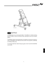
Page 3: ...are convinced that it will fully live up to your expec tations The Buffalo has been developed with an optimum of security and value in mind The Buffalo is for indoor use only and is to be used on a levelled non tilting surface only This manual has been made to help you gain as much use from the Buffalo as possible GB ...

Page 4: ...er joints in carpets over uneven surfaces or outside Guarantee Any R82 product bought with an R82 dealer includes a guarantee against defects in types and materials There is a 5 years guarantee on frame breaks The guarantee is given by the R82 dealer or subsequent R82 representative The guarantee can only be sustained if the R82 product is in use in the same country as produced for The guarantee d...

Page 5: ...ion Lift the standing frame out of the box and remove the plastic bag The foot plates and straps are included in the small box Mount the foot plates in the vertical bars and fasten with the handles A on the sides Mount the straps in the slots on each side of the basis plate Fasten with the finger screws B Angle the Buffalo into wanted position See instruction on page 11 Your Buffalo is now ready f...

Page 6: ...the black levers GB Heel support Duck Foot and frame extension Heel support A and duck foot B are mounted alike They are placed in the slots in the foot plates as shown below and fastened with the handle Mounting the frame extension C 1 Pop out the stopper and remove the wheel 2 Insert the extension 3 Fasten the extension and the wheel with the screws 4 Insert the stopper GB ...

Page 7: ...the Allen key C Then place the side supports in the fittings Adjust sideways and fasten with the black lever D GB Knee supports Place the fitting in the slot A and fasten in the desired height with the Allen key Then place the bar B in the fitting and fasten with the handle C Mount the knee support bars in the fittings and fasten with the Allen key The knee supports adjust sideways Use the finger ...

Page 8: ...te A Use a 4 mm Allen key 6 mm if Buffalo size 3 Mount the new 3 pipe fittings in the same holes on the plate Place the bar with the head support in the mid pipe and fasten with the handle B GB Pommel Place the pommel in the slot centered on the board Fasten from behind with the Allen key A GB ...

Page 9: ...move the two long go through bars Place the mounting brace for the back support and take the through bars back down through the mounting brace and into place B Fasten the mounting brace on the go through bars with the handles Fit the bars of the back support in the mounting brace and fasten with the Allen key C The pad on the back support can be adjusted si deways D The vertical bar with the pad s...

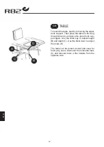
Page 10: ... the long through bars A and place the upper trunk sup port again Use the Allen key to adjust height B and depth C Use the black lever to adjust the angle D The table can be turned around and used for front lying users Dismount the horizontal bars C and remount them in the holders from the opposite side GB ...

Page 11: ...tal part B on the reverse side of the foot pedal can be turned to ac tivate deactivate the safetylock as shown in the diagram The Buffalo size 2 and 3 with manual tilt ang les from vertical into the horizontal position by loosening the handle C The security lock D will hold the tilt table Hold on to the tilt table and pull out the security lock D Slip the security lock when the tilt table is in th...

Page 12: ...lo size 2 3 1 In order to attach the control box fasten the plate in the holes Then attach the control box to the plate A power cable 220 V B remote control cable 2 Dismount the bar for the manual tilt at the top Use an Allen key and a 13 mm fork wrench 3 Then dismount the bar for the manual tilt below Use an Allen key and a 13 mm fork wrench GB ...

Page 13: ...ing the battery For an optimum lifetime of the battery it must charge for at least 12 hours before use 1 Connect the charger to the socket 2 When the battery box is plugged it starts charging 3 Charge the battery To gain the optimal profit of the angle adjust ment function the batteries must be charged every night The batteries can not be charged too much but do not ever let them drain com pletely...

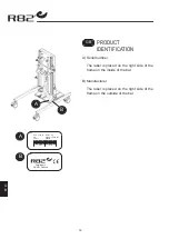
Page 14: ... 5707292 134158 Parallelvej 3 DK 8751 Gedved A B 14 G B Product identification A Serial number The label is placed on the right side of the frame on the inside of the bar B Manufacturer The label is placed on the right side of the frame on the outside of the bar GB ...

Page 15: ...5 115 30 45 90 135 35 53 125 170 49 67 Frame width W 49 19 54 21 62 24 Frame length L 70 28 85 33 111 44 Angling 0 90 0 90 0 90 Chest plate width 26 10 32 12 36 14 Chest plate height 24 9 27 10 36 14 Basis plate width 31 12 37 14 46 18 Basis plate height 44 17 56 21 81 31 Weight wo power 19 kg 42 lb 23 kg 51 lb 30 kg 66 lb Weight w power 29 kg 64 lb 36 kg 79 lb Max load 50 kg 110 lb 70 kg 154 lb 1...

Page 16: ...eel or powder lacquered steel Upholstery Wooden plate with fire resistant foam covered with fireresistant artificial leather Producer R82 A S Parallelvej 3 8751 Gedved Denmark Distributor Please find your distributor on www r82 com GB GB GB ...

Reviews: