background image

EM1500 User’s Manual

019-0124 • 070720-E

The latest revision of this manual is available on the Rabbit Semiconductor Web 

site, 

www.rabbit.com

for free, unregistered download.

Summary of Contents for EM1500

Page 1: ...EM1500 User s Manual 019 0124 070720 E The latest revision of this manual is available on the Rabbit Semiconductor Web site www rabbit com for free unregistered download...

Page 2: ...ks of Rabbit Semiconductor Windows is a registered trademark of Microsoft Corporation No part of the contents of this manual may be reproduced or transmitted in any form or by any means without the ex...

Page 3: ...Wiring the Demo Board to the Selected EM1500 16 2 3 3 Digital Output 16 2 3 4 Digital Input and Relay 17 Chapter 3 Assigning an IP Address to the EM1500 19 3 1 How to Obtain an IP Address 19 3 2 How t...

Page 4: ...ndix A EM1500 Specifications 77 A 1 Mechanical Characteristics 77 A 1 1 Base Plate 78 A 2 Specification Table 79 A 3 EM1500 EMI EMC Information 80 A 3 1 CE Compliance 80 A 3 2 EM1500 FCC Compliance 82...

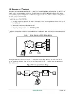
Page 5: ...n all be con nected to different hosts at the same time The remote host may also be another EM1500 In addition to the serial streams which are transferred via TCP Transmission Control Protocol sockets...

Page 6: ...Internet link is not the bottleneck Short term burst rates up to 1Mbit sec net Any one port may achieve up to 230400 bps FDX The EM1500 interfaces with all types of serial devices modems sensors card...

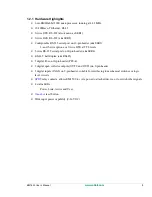
Page 7: ...at TTL levels 3 wire RS 232 serial port on 10 pin header aka SER4 RS 485 half duplex aka RS485 5 digital I 0s on 10 pin header PF0 4 2 digital open collector outputs OUT0 and OUT1 on 9 pin header 3 d...

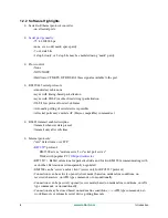
Page 8: ...485 transmit enable discipline transmit whenever data present transmit only after idle time Internet protocols raw data stream over TCP RFC2217 protocol EM1500 acts as modem server or serial port serv...

Page 9: ...rnet segment display dynamic unit status in near real time EM1500s can be partially reconfigured during operation without manual intervention using RFC2217 e g change serial port speed Auxiliary I Os...

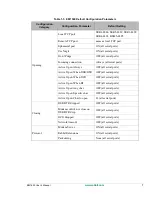
Page 10: ...Configuration Parameter Default Setting General Unit Name EM1500 fac dflt TCP Keepalives 7200 Aux I O Direction State PF0 4 In Low State OUT0 and OUT1 Hi Z Relay Open Network Ethernet Enable Connectio...

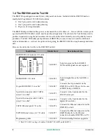
Page 11: ...OFF all serial ports Active Open When RI OFF all serial ports Active Open Any char OFF all serial ports Active Open Specific char OFF all serial ports Active Open Char to open 13 all serial ports Clo...

Page 12: ...Item Rabbit Part Description of Use DE9F DE9F null modem 10 ft cable 540 0063 Serial crossover cable for SER1 if DCD and RI signals are not required DE9M DE9F 10 ft cable 540 0052 Serial straight thru...

Page 13: ...ort files flash ini coldload bin pilot bin to download the firmware Rabbit screw driver 1 4 1 Rabbit Engineering Demo Board The demo board is useful for testing the functionality of the relay and digi...

Page 14: ...10 www rabbit com Introduction...

Page 15: ...net card Please note that neither the telnet example described in this chapter nor the configuration process described later in the manual have need of the EM1500 explicitly knowing the IP address of...

Page 16: ...ck sleeves you may determine which wire is which by looking on the label of the adapter Plug in the adapter and verify that the LED labeled PWR comes on steady 2 1 3 Serial Port Connection After makin...

Page 17: ...bring up the Serial port setup dialog The serial port geometry e g 8N1 character size is 8 bits there is no parity and there is one stop bit and speed are set in this dialog If you are using some othe...

Page 18: ...onfiguration for more infor mation about the stand alone program If using DHCP did not result in an IP address being assigned to the EM1500 you will need to assign one manually First get an IP address...

Page 19: ...OM port of the host PC The keyboard entries will then appear in the Tera Term window You may also send files from Tera Term by selecting File Send file from the Tera Term menu 2 3 Using the Demo Board...

Page 20: ...ND from the Demo Board to GND screw terminal on the EM1500 3 Connect the 9 wire assembly with plug that came with the Tool Kit to the 9 pin connector on the EM1500 The3 pins for the relay plus the 2 d...

Page 21: ...on the button is orange when off the color changes to gray Press down SW1 on the Demo Board Depending on the state of the relay you will see either IN0 or IN1 change from bright green to dark green i...

Page 22: ...18 www rabbit com Getting Started...

Page 23: ...will act as a server when it is deployed in the field you will need to have a permanent IP address assigned to it so that it can be contacted later The second way to obtain a valid IP address is to h...

Page 24: ...and one for Win dows emconf exe You will find the stand alone program on the CD that comes with the EM1500 Tool Kit Unlike directed ping this method does not require you to know an IP and MAC address...

Page 25: ...units at a time or you use directed ping to assign an IP address Figure 4 1 Front Panel of EM1500 Table 4 1 Front Panel Description Connector Description of Use RJ 45 Connects to 10 100Base T Ethernet...

Page 26: ...interface Orange with brief off period every second Run mode but no IP address has been obtained This means the unit has not been configured or it has been configured to use DHCP but no DHCP server i...

Page 27: ...female For connection to RS 232 serial port SER2 wired as a DCE 2x5 IDC header For connection to configurable serial port SER3 3 wire pins 3 Rx 5 Tx and 9 GND 5 wire pins 3 Rx 5 Tx 4 RTS 6 CTS and 9...

Page 28: ...figure below shows the pin out The black circles Tx DTR and RTS denote outputs The white circles denote inputs Figure 4 3 Pin Out for SER1 4 3 2 Serial Port 2 SER2 The serial port known as SER2 is wir...

Page 29: ...the factory SER3 and SER4 are configured as 3 wire RS 232 serial port avail able on pins 3 Rx and 5 Tx JP2 is jumpered on 1 3 and 2 4 meaning RS 232 signal levels for SER3 To change to TTL levels move...

Page 30: ...the figure below Note that a common signal ground is recommended Figure 4 6 Multidrop Network For best performance in a multidrop network termination resistors are enabled only on the end nodes and a...

Page 31: ...support Successful implementation of a particular protocol will require the correct configuration of several other items The most important of these are the specification of the transmitter enable di...

Page 32: ...of time Each packet must be transmitted without any gaps of more than 1 5 character times Following this specification the Serial tab for the RS485 port is set to Speed 115200 this is arbitrary provid...

Page 33: ...rt On the RS485 side packets are received for transmission to the network peer Since packets must be delimited by strict idle times on the RS485 side but may arrive from the network in piecemeal fashi...

Page 34: ...7 9 Pin Connector 4 3 6 10 Pin Connector The 10 pin connector is shown in Figure 4 5 If SER3 is not configured in software to be a 9 wire port 4 of the pins on the 10 pin connector PF0 3 become avail...

Page 35: ...lly in the GUI of emconf The categories are summarized here and explained fully in the rest of this chapter General This is where you set display router and nameserver addresses and the security optio...

Page 36: ...RFC2217 modem server as well as make it compatible with the use of a PC COM port redirector that complies with RFC2217 You may also choose to enable extensions to the protocol the exten sions are usef...

Page 37: ...e EM1500 entries Area 2 Status Debug for Selected Unit The area immediately under the listbox is the status debug area Unless an EM1500 entry is selected in the listbox the status debug area is empty...

Page 38: ...he unit name is a text string chosen by the user to uniquely identify the unit It may be left blank if the unit is unnamed A unit s name will be displayed in the listbox on the left side of the progra...

Page 39: ...his protection only applies to configuration The unit does not currently support any protection of the data connections Secure configuration is rec ommended if the EM1500 is to be connected to an Ethe...

Page 40: ...uration program is started and deleted when it fin ishes If the program is terminated forcibly e g by using the Task Manager then this file may be left in existence which will prevent the configuratio...

Page 41: ...be secure against snooping attacks The current firmware release does not support changing the key once it is set except by turning secure configuration off then back on The key is a 128 bit AES key a...

Page 42: ...F0 4 I Os on boot up If SER3 uses PF0 3 is checked then only PF4 is available as an extra I O line State These parameters control the initial state of the 2 open collector outputs of the EM1500 on boo...

Page 43: ...r one or more of the serial ports checked here is receiving or transmitting The user LED also gives status for the unit as a whole Please see Table 4 2 for a description of the possible LED patterns 5...

Page 44: ...is checked any IP address entered here will be used as a fallback if DHCP is not available IMPORTANT If the EM1500 is no longer readily accessible i e it s no longer on your desktop or maybe it s not...

Page 45: ...llow the use of a web browser for configuration Please see the Gen eral tab for instructions on how to select a login name and password to limit access by a web browser Enable config This must be chec...

Page 46: ...bit rates including non standard speeds The actual rates which are obtainable must be equal to the base clock divided by an integer between 6 and 256 inclusive The base clock is 1 382 400 Hz giving a...

Page 47: ...k the parity bit is always one Odd data bits plus the parity bit equals an odd number Even data bits plus the parity bit equals an even number Space and Mark are seldom used parity methods because the...

Page 48: ...ccept more data from the EM1500 XON XOFF software sent by the device receiving data to stop or restart the data flow DSR hardware an input to indicate that the attached device is ready DCD hardware an...

Page 49: ...oftware DTR hardware output to indicate that SER1 is ready These same options exist for SER3 when it is configured as a full DTE serial inter face If SER3 is not a full DTE serial interface then DTR i...

Page 50: ...h off Momentary on Momentary off Relay timer ms Relay timer for momentary actions NOTE It is possible to enter contradictory or nonsensical settings for the relay For example SER1 causes Latch on and...

Page 51: ...pline is defined Figure 5 6 Serial Tab for RS485 Tx Enable Transmitter enable control used for half duplex RS485 The choices are None Rx Idle Rx idle time char times If Rx Idle was chosen for transmit...

Page 52: ...epeating the AT prefix Commands can be strung together without spaces or spaces can be used to delimit the commands for readabil ity If commands are strung together then those commands which do not ta...

Page 53: ...cted redial DL Reconnect to the host that was last connected redial D domainname Connect to specified domain name e g em1500 foo com using the TCP port that was last used D domainname tcp_port Connect...

Page 54: ...g connection this gets out of AT command mode and back to normal data transfer mode Q0 Disable quiet mode i e respond with numeric or English result codes Q1 Enable quiet mode no responses V0 Use nume...

Page 55: ...asserted Kn Other flow control n is a number which has two fields The low 3 bits of n select the transmit flow control as follows 0 none 1 CTS or RTS for SER2 2 XON XOFF 3 DSR or DTR for SER2 4 DCD SE...

Page 56: ...ER2 only Specify how to use the RI modem control line The choices are Inactive Pulse for 1 second when connection first established 5 1 6 1 Modem Tab Parameters for SER3 and SER4 The configuration par...

Page 57: ...levels1 JP32 JP23 Comment4 0 0 x A D SER3 true 3 wire RS232 SER4 true 3 wire RS232 0 0 x B D SER3 true 3 wire RS232 SER4 3 wire TTL 0 0 x A E SER3 3 wire TTL SER4 true 3 wire RS232 0 0 x B E SER3 3 w...

Page 58: ...0 pin B means 3 5 and 4 6 i e SER4 is TTL on 10 pin C means 7 9 and 8 10 i e internal modem installed future option use PD4 5 on 10 pin for CTS RTS 3 JP2 is internal jumper setting D means JP2 is jump...

Page 59: ...tions become enabled These options are described below Note that polling is inserted by the EM1500 at arbitrary points from the point of view of the attached device or network peer Thus if you select...

Page 60: ...applied whether or not a network connection is established Oth erwise polling is only performed when there is no network connection This is most useful when packetizing is in use otherwise the pollin...

Page 61: ...in response to CRLF then that data will be forwarded over the network if a connection is established The next level up in complexity is to actually expect a particular response to a query For example...

Page 62: ...ed to include whitespace in a token then the token should be wrapped in single quote characters A backslash character in a token denotes an escape sequence for inserting special characters as follows...

Page 63: ...the choices for Incoming con nections and Active open Figure 5 10 Opening Tab for SER1 Local TCP port This is the local TCP port number for incoming connections from the network When acting as a serv...

Page 64: ...bandwidth requirements Don t Purge When checked data received by the serial port before a connection is established will be sent to the peer If not checked then pre connection data is discarded Check...

Page 65: ...e DCD indicates good carrier from remote modem Available on SER1 and SER3 as 9 wire port When RI Open when RI line becomes active Available on SER1 or SER3 as 9 wire port When any char received Open w...

Page 66: ...igured as a 9 wire port DTR dropped is available on SER2 Both DSR and DTR are used by attached serial devices to indicate that they are ready Modem control not close on DSR drop When DSR DTR line is d...

Page 67: ...m emulation software is active on this serial port Available on all serial ports Timeout ms This field may be filled in when Network timeout is checked It is the number of milliseconds that may elapse...

Page 68: ...ing connections will see this as an RFC2217 modem server Otherwise a raw data link is established NOTE This should be checked if you want to use a COM port redirector on a host PC to allow the PC to t...

Page 69: ...ode which recognizes the end of packet 9th bit mode looks for the start of the packet A packet is started by a 9th bit low This is not compatible with normal parity checking any parity setting in the...

Page 70: ...ytes 0 to 8 to send at end of packet This may be used if checksum fol lows terminating string etc It should only be used for String packetization other wise the results are undefined 5 1 11 Status Deb...

Page 71: ...he Internet with usually a reduction in response times The listbox and status debug area are pictured below One EM1500 responded to the broadcast so only one unit shows up in the listbox It has been s...

Page 72: ...ach serial port tray con tains mainly status information with but tons to manually override some functions The status indicators show the state of each of the modem control lines that are actually ava...

Page 73: ...the peers can get confused or crash in this case the connection sometimes gets stuck which requires a manual reset The text display on the 3rd and final line shows the current serial port setup inclu...

Page 74: ...signal The SER2 RTS LED will go off This prevents the EM1500 from transmitting more data out of its serial port Thus the Flow LED will come on yellow indicating a flow control stall If data is still...

Page 75: ...tting of a login name and password can be done from the stand alone program only 4 Multiple units may be configured during one session with the stand alone program A web browser may only point to one...

Page 76: ...72 www rabbit com EM1500 Configuration...

Page 77: ...pen check When any char received Make sure DHCP is disabled Do this for both units Using serial cables connect either SER1 or SER2 from each EM1500 to the free PC COM ports Then using the Ethernet cro...

Page 78: ...ght through M F cable Access to an Ethernet network from the PC and the EM1500 A likely scenario is a hub to which the PC and the EM1500 are both connected The EM1500 must be configured with the follo...

Page 79: ...r SER2 to the free PC COM port Now you need access to a network The EM1500 must be connected via its Ethernet port to a network to which the host PC is also connected It can be a small desktop LAN tha...

Page 80: ...when you configured the EM1500 You can define what TCP Wedge will consider the start and end of a record in the Input Data Record Structure a menu item from Defines There are two ways to cause TCP Wed...

Page 81: ...nmental specifications EMI EMC information Jumper locations for changing default behavior Battery life and replacement A 1 Mechanical Characteristics The following figure shows the mechanical dimensio...

Page 82: ...dimensions of the base plate and the locations of the mounting holes The base plate is made from 0 050 aluminum Figure A 2 Base Plate Dimensions 0 25 6 4 mm 4 60 116 8 mm 0 25 6 4 mm 3 78 96 mm 4 10...

Page 83: ...elay Output SPDT 1 A 30 V DC 0 3 A 120 V AC Serial Ports 1 DTE RS 232 1 DCE RS 232 1 RS 485 half duplex 1 configurable serial port 3 5 and 9 wire option 1 3 wire RS 232 Serial Rate 75 230400 bps 7 8 d...

Page 84: ...mity with the following applicable immunity and emission standards EM1500s that are CE compliant have a label with the CE mark on the front panel of the unit similar to that shown in Figure A 3 Figure...

Page 85: ...gn practices When installing or servicing the EM1500 it is the responsibility of the end user to use proper ESD pre cautions to prevent ESD damage to the EM1500 To meet EMC requirements and in particu...

Page 86: ...ection against harmful interference in a residential installation This equipment generates uses and can radiate radio frequency energy and if not installed and used in accordance with the instructions...

Page 87: ...the black box housing The following figure shows the jumper header locations The dashed line represents the location of the Rabbit Core Module Header JP5 which is used to configure the RS 485 bias an...

Page 88: ...ins Connected Factory Default JP1 Digital inputs pulled up 1 2 Digital inputs pulled down 2 3 JP2 RS 232 levels for SER3 Rx Tx 1 3 2 4 TTL levels for SER3 Rx Tx 3 5 4 6 JP3 RS 232 levels for CTS RTS l...

Page 89: ...he Backup Battery To replace the battery first remove the old one The battery snaps in and out of place so just apply pres sure under its rim to get it out Use a Renata CR2477N or equivalent replaceme...

Page 90: ...86 www rabbit com EM1500 Specifications...

Page 91: ...not eliminate the confusion but helps minimize it The following discussion focuses on the electrical connections between two RS232 devices Once this is established we talk about the data signalling c...

Page 92: ...s state of the attached devices These lines DTR Data Terminal Ready and DSR Data Set Ready i e modem ready are less important than RTS CTS but are nevertheless used often The wiring for these is And i...

Page 93: ...asing set of capabilities The first arrangement with only Tx and Rx is known as 3 wire Adding RTS and CTS gives 5 wire The last arrangement is full 9 wire 7 wire is also possible dropping the problema...

Page 94: ...ate and 12 V when inactive A discon nected input will yield 0 V which will be interpreted as inactive which is as it should be Now the computer equipment which is using RS232 is probably happier with...

Page 95: ...fer capacity is simply dis carded It is then up to the higher level application to realize that data has gone missing When a 3 wire link is in use the only alternative is to insert some special signal...

Page 96: ...ely used but some equipment may require it The EM1500 handles hardware flow control as follows When the receive buffer becomes approximately half full about 500 bytes then the RTS line is dropped The...

Page 97: ...data including XON XOFF when it is throttled but that would be violating the flow con trol rules The EM1500 handles XON XOFF flow control as follows It assumes the data stream from the network does no...

Page 98: ...e sends an XOFF to pause the flow For the above reason it is best to use end to end flow control only when the network bandwidth is high and the latency short in practice that means that the network c...

Page 99: ...the data stream will be corrupted If you are using some of the more advanced features of the EM1500 like packetization and protocol trans lation then you will have to use Rabbit extensions Without thi...

Page 100: ...the packet must be sent in one continuous stream the entire packet must be buffered in the EM1500 before it can start being sent If only part of the packet had been received from the network the EM15...

Page 101: ...his is from the point of view of the serial device and is unrelated to the length limitation imposed on a TCP packet Packets are terminated when a particular character sequence is received The string...

Page 102: ...tion and the other uses idle timing The end that uses idle timing cannot start sending a packet until the EOP indicator is received Thus if the 9th bit end does not get a new packet for a long time th...

Page 103: ...etwork latency is low and it is desired to start transmitting the packet even before the EOP indicator has been received This is usually only needed for idle packetizing mode and is done in the hope t...

Page 104: ...100 www rabbit com Serial and TCP Protocols...

Page 105: ...l port A COM port redirector is a good solution for legacy software applications that you either can not or will not modify A Google search shows that there are many of these products available on the...

Page 106: ...ed when the DTE is ready to receive CTS Clear to Send an input the DTE waits for before sending DTR Data Terminal Ready an output to indicate readiness DSR Data Set Ready an input to indicate readines...

Page 107: ...odem Server A modem server allows multiple user connections at one time The name originates from the fact that it applies to multiple users of a modem but it applies to other uses as well E g a device...

Page 108: ...match on both ends of the connection They are number of bits per character parity number of stop bits These parameters are usually abbreviated e g 8N1 means that there are 8 bits per character no pari...

Page 109: ...uy an EM1500 Why are there 2 types of serial cables in the EM1500 Tool Kit Why are there 2 types of Ethernet cables in the EM1500 Tool Kit Network Why is there no default IP address for the EM1500 Why...

Page 110: ...I set web browser userid and password but now the browser can t log in even though I am supply ing the correct userid and password What has gone wrong I checked Secure config in the General tab I got...

Page 111: ...there no default IP address for the EM1500 A What would it be There are however 2 default configurations that you can easily copy to your EM1500 if you are using the stand alone configuration program...

Page 112: ...t panic You can recover from this without losing your configuration settings You must do a hard reset of the EM1500 back to its factory default condition Do this by holding the reset button down for...

Page 113: ...er of stop bits set for the serial port of the EM1500 must match those set for the attached serial device For SER3 and SER4 also check the jumper settings for JP2 and JP3 to make sure they are set to...

Page 114: ...set up the telnet connections Q Can I monitor the data that is sent received by a serial port A Not directly however there are several ways of doing this Use an Ethernet sniffer program such as Ethere...

Page 115: ...nfiguration parameters as an entry in a configuration database All you do is select the EM1500 whose settingsyou wish to save and press Ctrl C Now select a configuration database In the screencapturep...

Page 116: ...browser s stop button if necessary then manually type in the unit s new IP address e g http 10 10 9 99 If the new IP address is valid the browser should be able to pick up from there If this did not f...

Page 117: ...cess the unit any more and it doesn t even come up in the list of units A Check that You are using the same PC that you initially used to turn on secure config The secret keys are held on only one mac...

Page 118: ...114 www rabbit com EM1500 FAQ...

Page 119: ...scovery 41 DNS name server 35 DSR 44 52 61 62 DTR 44 51 61 62 E EMI EMC information 80 82 emissions standards 81 F FCC compliance 82 H hardware connections 11 hub 12 I immunity standards 80 IP address...

Page 120: ...rabbit com router 35 RS 485 26 29 RTS 44 52 88 S secure configuration 35 send expect 57 58 straight through cable 8 12 87 89 T technical support 9 throughput 2 transmit buffer 96 U User LED 22 V volt...

Reviews: