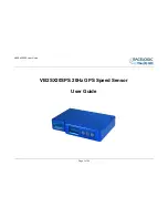
background image

VB2SX20SPS User Guide 


Page 1 of 24 


VB2SX20SPS 20Hz GPS Speed Sensor 


User Guide 


Summary of Contents for User Guide

Page 1: ...VB2SX20SPS User Guide Page 1 of 24 VB2SX20SPS 20Hz GPS Speed Sensor User Guide...

Page 2: ...ORY 5 OPERATION 6 DISPLAY SCREEN 6 FRONT PANEL CONTROLS 7 SMOOTHING AND FILTERING 9 GPS ANTENNA 10 GETTING STARTED 15 VBOXTOOLS SOFTWARE 17 UPGRADING THE FIRMWARE 17 SPECIFICATION 18 CONNECTOR ASSIGNM...

Page 3: ...s of the member states relating to the type approval of motor vehicles and their trailers And has also been assessed via Technical Construction File by an independent DTI Competent Body and found to b...

Page 4: ...compatible with the VBOX Multifunction Display DSP03 and the VBOX LED Display DSP02 older DSP02s may require a firmware upgrade However the VB2SX20SPS can not be used with VBOXTools for real time mon...

Page 5: ...1 RLCAB042 Analogue Output Cable 1 RLCAB008 Digital Output Cable 1 RLCAB009 2 Way LEMO to 3 Wire Un terminated Power Cable 1 RLCAB014 5 Way LEMO to 9 Way D Connector CAN Cable 1 RLCAB019L Padded Carry...

Page 6: ...ring normal operation the display screen displays Speed mph or km h as well as the number of satellites that the VB2SX20SPS has locked on to There are also two satellite status displays and a DGPS sta...

Page 7: ...set between 0 4 Velocity must t be set to 0 for Brake stop tests Press to perform a GPS cold start Press to enter the DGPS Menu then and to move to the desired option Then press to confirm Note that...

Page 8: ...to confirm 1 50kHz in 0 1kHz steps TEST BACK Press and then use the and buttons to set a test value that the Digital output will simulate Then press to quit Press to exit the digital setup menu and ca...

Page 9: ...high dynamic tests where Time or Distance measurements are critical to the test such as Brake stop and acceleration tests Kalman Filter This filter provides filtering separately to the Velocity and P...

Page 10: ...satellite reception The GPS antenna works best with a metal ground plane underneath eg Vehicle roof Please also note that when using any GPS equipment a clear sky view is important Objects in the surr...

Page 11: ...ing to velocity long ACC or Lat ACC The frequency range is adjustable in software or via the front panel controls The analogue outputs on connectors OUT1 and OUT2 output are a 0V to 5V DC signal corre...

Page 12: ...is able to record precisely an event time for use in brake distance calculation This period of time is called the trigger event time and is given as the value in milliseconds between the trigger event...

Page 13: ...proprietary serial data format Note that only the USB port is used for firmware upgrading whilst only the RS232 socket may be used to transmit data to a VBOX LED Display RLVBDSP02 The CAN Bus port is...

Page 14: ...o not this time and click Next see image right A new window will appear at this window click Next see image below A new Hardware Installation window will appear Click the button labelled Continue Anyw...

Page 15: ...2SX20SPS Power supply cable CAB14 GPS Antenna USB RS232 Cable VBOXTools Software CD Laptop PC not supplied 1 Install Software 2 Place VBOX in vehicle 3 Fit antenna connector to VBOX 4 Mount GPS antenn...

Page 16: ...umber of satellites currently in lock For best results ensure the VBOX has acquired a lock on 5 or more satellites essential for quality signal reception When using the VBOX for the first time or when...

Page 17: ...wnload it from the website and copy it to your computer If you are connecting your slip angle sensor to your computer with the USB cable for the first time then follow the instructions in the Section...

Page 18: ...Accuracy 3m 95 CEP Resolution 0 01 s Accuracy with DGPS 1 8m 95 CEP Accuracy 0 01 s Update rate 20 Hz Resolution 1 cm Heading Power Resolution 0 01 Input Voltage range 6v 30v DC Accuracy 0 1 Current...

Page 19: ...e 0 to 5Volts DC Frequency range DC to 44 4Khz Default setting Velocity 0 0125Volts per Km h 0 to 400Km h Default setting 25Hz per Km h 0 to 400Km h Accuracy 0 1 Km h 90 pulses per metre Update rate 2...

Page 20: ...Power 2 I Ground Chassis I Ground Connector 2 3 OUT 1 OUT 2 One Analogue and One Digital Output Each Pin I O Function 1 O Analogue Out 1 2 2 O Digital Out 1 2 3 I Ground Chassis I Ground Connector 4...

Page 21: ...nector 6 CAN Low 5 I O Power Chassis I Ground Connector 6 SERIAL Setup Upgrade Second CAN Bus Connector Pin I O Function 1 O RS232 Tx Serial Data transmit 2 I RS232 Rx Serial Data receive 3 I O CAN Hi...

Page 22: ...ds 3 Position Latitude 100 000 515924579 51 Degrees 59 24579 Minutes North Latitude highest bit indicates north south hemisphere 0 north 1 south Bit 7 in Status is also set 4 Position Longitude 100 00...

Page 23: ...on The VB2SX20SPS contains a fuse to protect it from excessive currents If the unit is accidentally subjected to large currents and the fuse has become tripped it can be reset by pressing the button m...

Page 24: ...mail support racelogic co uk Web www racelogic co uk Revision Date Description Author 1 13 07 2007 First release JH 2 03 12 2007 Addition of Format Motorola to CAN Bus Data Format table NT 3 30 04 200...

Reviews: