background image

VBOX 3iSL User Guide  


Page 1 of 49 

01/12/2011 

VBOX 3iSL 100Hz GPS Data Logger 

User Guide 

Summary of Contents for VBOX 3iSL

Page 1: ...VBOX 3iSL User Guide Page 1 of 49 01 12 2011 VBOX 3iSL 100Hz GPS Data Logger User Guide...

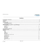
Page 2: ...ing VBOX Manager 9 Antenna Separation 9 Roll Mode 10 Swap Antennas 10 Align Antennas 11 Level Antennas 12 Parts Supplied with VBOX 3iSL 13 Optional Accessories 13 Operation 14 Power 14 Buttons 15 Logg...

Page 3: ...32 Software Installation 32 IMU Integration 33 Hardware configuration 34 Hardware Set Up 36 Upgrading the VBOX 3iSL s Firmware 37 How to Upgrade the Firmware 37 Troubleshooting Guide 38 VBOX 3iSL Spe...

Page 4: ...e laws of the member states relating to the type approval of motor vehicles and their trailers And has also been assessed via Technical Construction File by an independent DTI Competent Body and found...

Page 5: ...flash card for easy transfer to PC The VB3i SL also includes 4 high resolution analogue input channels to record data from external sensors and 2 CAN bus interfaces to allow connection of Racelogic in...

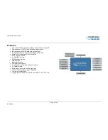
Page 6: ...s differential analogue inputs 50v Brake Event trigger input of 10ns resolution Voice Tagging of Data 2 x CAN Bus interface RS 232 serial interface USB Interface Bluetooth Interface Compact Flash Inte...

Page 7: ...r of the car and the secondary antenna Socket B at the front All measurements are made from the primary antenna 6 If you want to measure slip at the front of the vehicle swap the antenna connections a...

Page 8: ...lacement of the antennas It is essential that the separation of Antenna B from Antenna A is exactly the same as the separation value set inside the VBOX3iSL via the VBOX Manager If the separation is i...

Page 9: ...the user should see the full Dual Antenna menu system with a tick shown next to Enable Antenna Separation The most important factor for dual antenna testing is the correct configuration of the separat...

Page 10: ...he width of the car to measure roll angle then the Roll Mode option must be toggled in the Dual Antenna menu Click this option to toggle between Pitch Mode no tick and Roll Mode tick Swap Antennas Whe...

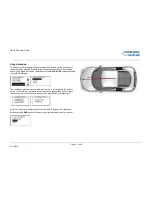
Page 11: ...oved using the AUTO ALIGN feature available in the VBOX Manager The calibration process requires the driver to drive in a straight line for a short period of time whilst maintaining a constant speed g...

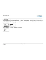
Page 12: ...und If the roof of your vehicle is not perfectly flat in relation to the ground then this will show up as a Pitch offset You can automatically remove any offset by performing the AUTO LEVEL feature av...

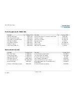
Page 13: ...y case 1 RLVBACS113V4 VBOX Tools Installation CD 1 RLVBACS030 VBOX 3iSL Audio Headset 1 RLACS120 Optional Accessories Description Racelogic Part Description Racelogic Part Brake Pedal Trigger RLVBACS0...

Page 14: ...d to the VBOX will be at the same level as the VBOX power input Therefore when using any of the Racelogic peripherals with VBOX 3iSL the input voltage must not exceed 15 volts Failure to observe this...

Page 15: ...ted When the VBOX is logging the blue CF light flashes Do not remove the CF card or power down whilst this LED is flashing if you need to remove the card or power down whilst the CF light is flashing...

Page 16: ...cked then the VBOX will only log data to the CF card when it detects speed 0 5Km h Advanced The advanced logging option on a VBOX 3iSL allows any of the logged data channels to be used to trigger the...

Page 17: ...GPS Satellites currently being tracked Each flash indicates a satellite with a short pause between each sequence Flashing Orange sequence indicates the number of GLONASS Satellites currently being tr...

Page 18: ...gged Flashing Green indicates that there is incoming Serial traffic through this socket BLUETOOTH UNLIT indicates Bluetooth waiting for a connection Solid BLUE indicates the VBOX 3iSL has a Bluetooth...

Page 19: ...rounding area such as tall buildings or trees can block the GPS signal causing a reduction in the number of satellites being tracked or introducing reflected signals that can decrease the accuracy of...

Page 20: ...threshold level can be set for the selected data channel where a true condition gives a 5v output and a false condition gives a 0v i e Data channel Speed threshold 40Km h When speed is 40 output 5V s...

Page 21: ...cisely the trigger event time 10nS resolution for use in brake distance calculation This period of time is called the trigger event time and is logged and used to correct the measured brake stop dista...

Page 22: ...an option for easy connection of signal pins Using VBOXTools software logging of the analogue channel data can be switched on or off It is also possible to change the name of each input channel and co...

Page 23: ...imum accuracy tests performed at a GPS sample rate above 20Hz should be logged to compact flash and post processed The secondary RS232 port is used for connection to a Telemetry Radio module allowing...

Page 24: ...Database giving the user the ability to log basic CAN data from a large number of current vehicles from a broad selection of manufacturers This CANALLCAR REF file should be installed as part of the s...

Page 25: ...identifiers Eg VBOX3iSL can log IMU data on one CAN bus and output the IMU data to third party equipment on second CAN bus with a user defined identifier A VBOX3iSL can output up to 6 CAN messages and...

Page 26: ...speed i e no satellite signal complete satellite drop out A VBOX 3iSL will scale the input channel to the default speed output format of Km h according to what the units have been assigned to the sub...

Page 27: ...he vehicle test incorporates highly dynamic manoeuvres Normal The Normal mode should only be used for any testing that does not involve any high dynamic manoeuvres Low Dynamics The Low dynamics mode c...

Page 28: ...uring the signal from satellites at low elevation Raising the mask will cause the GPS engine to ignore satellites below the mask angle so must be used carefully as it also reduces the total number of...

Page 29: ...recognise the presence of new hardware and open the typical Windows install window for new hardware Follow the on screen prompts and point the Windows installation to the location of your drivers Not...

Page 30: ...ound an audible beep through the headset to confirm that recording of the WAV file has begun Pressing the switch for a second time will then stop recording this will be confirmed by a second beep thro...

Page 31: ...orted into third party applications such as word processors or spreadsheets The files each contain a header section before the main data that describes the channel content and information about the VB...

Page 32: ...Software Installation The VBOX 3iSL setup software must be installed onto the hard drive of a computer it cannot be run from the installation CD To install the software insert the CD into the CD driv...

Page 33: ...ntial factors Inertial sensor measurements on the other hand are continuously available but suffer from long term drift due to the accumulation of integration errors of the accelerometer and gyro meas...

Page 34: ...les tab should be visible This indicates the IMU has been correctly detected by the VBOX 3iSL 6 If the 3 axis Modules tab is not visible click on the CAN button at the top of the window 7 Make sure th...

Page 35: ...the raw unfiltered GPS data If however an IMU is connected after the VBOX 3i has begun to log data the file will contain a mix of unfiltered and filtered data 11 Once the VBOX 3iSL has been set up to...

Page 36: ...used to accurately align the IMU to ensure the Kalman filter uses IMU data that is as accurately aligned with the vehicle 5 Adjust the position of the IMU while observing the resulting change of the I...

Page 37: ...w to Upgrade the Firmware To upgrade the firmware power the VBOX 3iSL and wait until the box has finished initialisation Insert the CF card containing the upgrade file Once the upgrade is complete the...

Page 38: ...odule is most likely not enabled Communicate with your VB3i SL using VBOX Tools software Enter VBOX Setup then access the GPS tab and check the enable slip module box After you have pressed this the b...

Page 39: ...connected to either SER or CAN dedicated to the Racelogic CAN bus Check the port the VBOX File Manager is connected to has CAN termination set VB3i SL Locked up If the VB3i SL unit is unresponsive pe...

Page 40: ...ed view of the skies until the GPS LED becomes solid green Once the VBOX 3iSL has downloaded the new almanac it will reacquire satellites in noisy situations such as near trees buildings and under bri...

Page 41: ...Pitch and Roll Angle Resolution 0 01 Accuracy Accuracy 0 1 1 0 rms at 0 5m antenna separation 0 25 rms at 2m antenna separation Acceleration Power Accuracy 0 5 Input Voltage range 7v 30v DC Maximum 0...

Page 42: ...25Hz per Km h 0 to 400Km h Accuracy 0 1 Km h 90 pulses per metre Update rate 100Hz Accuracy 0 1Km h Update rate 100Hz The range settings can be adjusted by the user in software Inputs CAN Bus Racelog...

Page 43: ...VBOX 3iSL User Guide Page 43 of 49 01 12 2011 Connection Data Front View of VBOX3iSL 2 pin LEMO socket 3 pin LEMO socket 5 pin LEMO socket...

Page 44: ...n Range 1 O Analogue 1 Output 0V to 5V 2 O Digital 2 Output 0V to 5V 3 I Ground Connector 3 AD 2 Type Lemo 3 pin PIN In Out Description Range 1 O Analogue 2 Output 0V to 5V 2 O Digital 1 Output 0V to...

Page 45: ...N Bus High PORT A 4 I O CAN Bus Low PORT A 5 O V Power Same as Power Connector 6 SER Type Lemo 5 pin PIN In Out Description Range 1 O RS232 Tx PORT A 12v 2 I RS232 Rx PORT A 12v 3 I O CAN Bus High POR...

Page 46: ...ption Range PIN In Out Description Range 1 I Channel 1 14 O Vbatt Equal to Input Voltage 100mA 2 I Channel 1 15 O GND 3 I Channel 2 16 O Iso 5 V Out Isolated 5V 2 100mA 4 I Channel 2 17 O Iso GND Isol...

Page 47: ...Knots 6 Heading Degrees 0x303 10ms 7 Altitude WGS 84 Metres 8 Vertical velocity M S Unused 9 Status 10 Status 0x304 10ms 11 Distance Meters 12 Longitudinal Accel G 13 Lateral Accel G 0x305 10ms 14 Dis...

Page 48: ...Closed CAN Bus 1 open 2 VBOX3 10 Status is an 8 bit unsigned char Bit 0 is always set Bit 3 brake test started Bit 4 Brake trigger active Bit 5 DGPS active 11 Distance 0 000078125 meters per bit unsig...

Page 49: ...ft 28 Jan 09 Draft Version of Document AM 1 29 April 09 31 34 IMU integration setup added AM 2 6 May 09 34 Change to Pitch and Roll statement in IMU integrations section KB 3 11 May 09 37 Update to GP...

Reviews: