background image


MM200 

High Speed 

Microwave Modem 

Installation and Operation Manual 


TM086 - Rev. 4.1 


Comtech EF Data  

  2114 W 7

th

 St.  

  Tempe, AZ  85281  

  (480) 333-2200  

  Fax: (480) 333-2540  

  www.comtechefdata.com

Summary of Contents for MM200

Page 1: ...MM200 High Speed Microwave Modem Installation and Operation Manual TM086 Rev 4 1 Comtech EF Data 2114 W 7th St Tempe AZ 85281 480 333 2200 Fax 480 333 2540 www comtechefdata com...

Page 2: ......

Page 3: ...serial number of any of its parts has been altered defaced or removed The warranty does not cover damage or loss incurred in transportation of the product The warranty does not cover replacement or re...

Page 4: ...ated as acceptable to Comtech EF Data Return Authorization Number must be clearly marked on the shipping label Returned products or parts should be carefully packaged in the original container if poss...

Page 5: ...wn in less than and greater than brackets For example the Reset Alarms Pushbutton will be shown as RESET ALARMS while a command that calls for the entry of a 7 followed by ENTER Key will be represente...

Page 6: ...ations or warranties concerning the products described Comtech EF Data assumes no responsibility for use of any circuitry other than the circuitry employed in Comtech EF Data systems and equipment Fur...

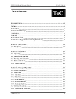
Page 7: ...ly ____________________________________________ 2 2 2 3 Mounting Considerations ___________________________________________ 2 2 2 4 Modem Checkout _________________________________________________ 2 2...

Page 8: ...____ 4 4 4 3 Level 2 Menu Screens _____________________________________________ 4 4 4 3 1 Main Menu Screens ______________________________________________ 4 4 4 3 2 MODULATOR menu ____________________...

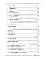
Page 9: ..._____________ 4 39 4 10 Experimental _________________________________________________ 4 39 4 11 Private _____________________________________________________ 4 39 4 12 Terminal Port User Interface___...

Page 10: ..._______________________ 5 1 5 1 1 AC Power______________________________________________________ 5 1 5 1 2 DC Power______________________________________________________ 5 1 5 2 Alarm Port____________...

Page 11: ...________________________ 5 10 5 14 Wayside G 703 T1 E1 Rear Panel Interface __________________________ 5 10 5 14 1 IN Female BNC Connector J15 __________________________________ 5 10 5 14 2 OUT Female...

Page 12: ...ntroduction ______________________________________________________ 7 1 7 1 Specifications ____________________________________________________ 7 1 7 2 Options _________________________________________...

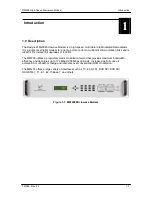
Page 13: ...on links and is ideal for microwave link upgrades or retrofits The MM200 utilizes a proprietary matrix modulation format that provides maximum bandwidth efficiency and data rates up to 176 Mbps 200 Mb...

Page 14: ...Introduction MM200 High Speed Microwave Modem 1 2 TM086 Rev 4 1...

Page 15: ...ettings located inside the MM200 chassis There is a potential shock hazard internally at the power supply module DO NOT open the MM200 chassis under any circumstances Before initially applying power t...

Page 16: ...ws air in from the left hand side and exhausts from the right rear and side as viewed from the front Do not install the unit in closed locations where this airflow will be restricted The exhaust air m...

Page 17: ...uld disrupt existing communications traffic New units from the factory are normally shipped in a default configuration which includes setting the transmit carrier off Turn the unit ON by applying powe...

Page 18: ...Installation MM200 High Speed Microwave Modem 2 2 TM086 Rev 4 1...

Page 19: ...ve systems An extremely powerful equalizer working at the lower symbol rate removes multipath and is coupled with Reed Solomon Noise Reduction System to form a robust reliable communications link Addi...

Page 20: ...and mux demux overhead The ratio between multiplexer input data and output data is 184 204 To accommodate changes in the data rate supplied by the customer and the constant output of the mux the gaps...

Page 21: ...ier The Tx interface must match the Rx interface 3 1 5 Diversity Option When the system requires Diversity such as Space Diversity or Frequency Diversity the receiving site must have two independent r...

Page 22: ...ble ensure all other interfaces are disabled 9 Set Interface to T3 10 Set Data Inv to Norm 11 Set the bandwidth in the Demodulator Menu to 30 000 000 3 2 2 2 Transmitting STM 1 From Interface Slot 1 o...

Page 23: ...ion the MM200 was designed to work with radios that have automatic gain control AGC The radio AGC will generally use the average power of all the IF channels to set its power unlike the MM200 that ind...

Page 24: ...Theory of Operation MM200 High Speed Microwave Modem 3 6 TM086 Rev 4 1...

Page 25: ...y and status LEDs The front panel layout is shown in Figure 4 1 showing the location and labeling of the front panel The front panel is divided into four functional areas the Front Panel LCD Display t...

Page 26: ...e Key Functions Front Panel Only Parameter Type 0 9 Clear Clear Fixed Point Decimal Changes Digit Toggles If Signed Toggles If Signed Moves Cursor 1 Position Left Moves Cursor 1 Position Right N A N A...

Page 27: ...eceive learning condition Test Mode Yellow Indicates the modem is involved in a current test mode activity Power Green Indicates the MM200 unit is currently powered up Fault Red Indicates a general eq...

Page 28: ...evel 2 is the default setting and is shipped from the factory in this mode The screens are available that provide the quickest form of setup and use Note Screens Menus are listed below by level L0 L1...

Page 29: ...de possible for the required bandwidth RO BANDWIDTH Hz Enters the 3 dB bandwidth of the modulated IF Output When the radio must meet a particular spectral mask set this number to something below the m...

Page 30: ...hat is being used by the selected interfaces Must be less than 100 Maximize this number for best bandwidth efficiency by lowering the symbol rate QAM Mode or the number of channels RO MAX PAYLOAD Hz D...

Page 31: ...ft possible loss of lock To overcome this once acquired the demodulator reduces this offset to 0 Hz by slowly incrementing decrementing the demodulator frequency The speed can be adjusted by adjusting...

Page 32: ...Displays the Channel A and B error counter RW RW RW RO RO RO 4 3 4 REPEATER Menu The primary Repeater screen is listed below Screen Name Selections and Descriptions L2 MODE Off On Enables the repeater...

Page 33: ...ce 1 Disable Enable Enables or disables the installed interface Dependant upon interface type For variable interfaces this unit must be set by the user Will not show up on fixed rate interfaces Depend...

Page 34: ...Refer to TX INTRFC1 menu for descriptions TX INTRFC3 menu Transmit Interface 3 Refer to TX INTRFC1 menu for descriptions TX INTRFC4 menu Transmit Interface 4 Refer to TX INTRFC1 menu for descriptions...

Page 35: ...pears when using DVB Framed Interfaces such as L0I Normal Inverted Sets the polarity of the clock Note Only appears when supported by the installed interface Normal Inverted Sets the polarity of the d...

Page 36: ...RX INTRFC3 Receive Interface 3 Refer to RX INTRFC1 menu for descriptions RX INTRFC4 Receive Interface 4 Refer to RX INTRFC1 menu for descriptions 4 4 All Level Menu Screens 4 4 1 Main Menu Screens Mai...

Page 37: ...he required bandwidth RW RW RO BANDWIDTH Hz Enters the 3 dB bandwidth of the modulated IF Output When the radio must meet a particular spectral mask set this number to something below the masks 3 dB p...

Page 38: ...upper 3 dB point and the lowest channel s lower 3 dB point RO RO RW UTILIZATION Displays the percentage of the data being transferred that is being used by the selected interfaces Must be less than 10...

Page 39: ...to demodulator frequency acquisition window and radio drift This can cause degraded performance and in the case of radio drift possible loss of lock To overcome this once acquired the demodulator red...

Page 40: ...HANNEL A ERR CHANNEL B ERR CHANNEL AB ERR Diversity Disable Auto Force A Force B Controls the diversity mode Diversity channel and FIFO status Unused Channel A Channel B Null Frames Specifies the mult...

Page 41: ...LEVEL dBm HYSTERESIS MONITOR menu XMT STATUS RCV STATUS APC Transmit settings TXDOWN TXUP AUTO Controls the local TX level Sets the maximum TX power level Displays the minimum TX power level Sets the...

Page 42: ...Shows only in DVB Framed Interfaces Note Only appears when supported by the installed interface NORMAL STAMP2 STAMP3 Normal or Time Stamped packets 2 Byte Packet ID Defines the 2 byte packet ID progr...

Page 43: ...on 0 255 Allows the user to set volume level Orderwire only RW RW RW TX INTRFC2 menu Transmit Interface 2 Refer to TX INTRFC1 menu for descriptions TX INTRFC3 menu Transmit Interface 3 Refer to TX INT...

Page 44: ...ows only in DVB Framed Interfaces Note Only appears when supported by the installed interface INCH SLOW MEDIUM FAST STAMP2 STAMP3 Clock recovery DLL speed or Time Stamped packets 2 Byte Packet ID Defi...

Page 45: ...needed 0 255 Allows the user to set volume level Orderwire only Note Only appears when supported by the installed interface 0 255 Allows the user to set ASI byte gapping Set to 0 for Burst mode ASI In...

Page 46: ...355 35 5 dB 000 655 000 655 000 655 000 655 Displays a relative indication of the AGC level of each channel Optimum performance is approximately 320 420 The lower the number the higher the IF signal M...

Page 47: ...lexor Interface 1 tx data rate KBPS Interface 2 tx data rate KBPS Interface 3 tx data rate KBPS Interface 4 tx data rate KBPS RO RO RO RO RO RO RO RO RO RO RO RO MON DMX menu RX INTF1 RATE RX INTF2 RA...

Page 48: ...scriptions L0 L1 L2 ACTIVE ALRMS menu Current alarms LATCHED ALRM menu Previous alarms that have been logged CLEAR ALARMS Ent Y Clr N Clears all latched alarms 4 4 8 1 Active Alarms The Active Alarm S...

Page 49: ...D will illuminate FPGA failure FPGA failure Monitors the system signal lock states Monitors the system sync lock states Monitors the data PLL lock states FPGA failure FPGA failure FPGA failure FPGA fa...

Page 50: ...ect Modulator tracking Modulator has a valid sync lock Modulator FIFO overflow Modulator FIFO underflow Modulator FIFO active Refer to CHANNEL 0 menu for descriptions Refer to CHANNEL 0 menu for descr...

Page 51: ...D will illuminate No clock activity on Tx Interface channel No data activity on Tx Interface channel Tx Interface FIFO overflow Tx Interface FIFO underflow Tx Interface MPEG framing Tx Interface loss...

Page 52: ...SYSTEM Menu The System Screens are listed below Screen Name Selections and Descriptions L0 L1 L2 CONTROL MODE Front Panel Computer Allows the user to choose whether the system is controlled from the F...

Page 53: ...ess of the remote port Sets the baud rate of the remote port RS485 RS232 Sets line control for remote port RW RW RW RW RW RW RW RW RW TERMINAL menu TERM BAUD EMULATION Sets the baud rate of the termin...

Page 54: ...15 M 2 23 2 23 M Breaks the data path and inserts a pseudo random sequence into the modulators None is used for normal operation the others are for Radyne Inc configuration RW RW RW REMOTE TAPS NORMAL...

Page 55: ...other ancillary support gear Communication is bi directional and is normally established on one or more full duplex multi drop control buses that conform to EIA Standard RS 485 Each piece of earth sta...

Page 56: ...nformation framing and correct equipment acknowledgment and data transfers OPCODE The Operation Code field contains a number that identifies the message type associated with the data that follows it A...

Page 57: ...ror control and handshaking A different FSN is produced for each new message from the FSN originator to a specific device on the control bus If a command packet is sent and not received at its intende...

Page 58: ...e same manner These are summarized as follows all Opcode values are expressed in decimal form Table 4 5 Response OPCODES RESPONSE OPCODE DESCRIPTION OPCODE Good Message 000d 0x0000 Bad Parameter 255d...

Page 59: ...CY_ERROR 0x021F REMOTE_FREQUENCY1_ERROR 0x0220 REMOTE_FREQUENCY2_ERROR 0x0221 REMOTE_FREQUENCY3_ERROR 0x0222 REMOTE_FREQUENCY4_ERROR 0x0223 REMOTE_FREQUENCYPLAN_ERROR 0x0224 REMOTE_USERMODE_ERROR 0x02...

Page 60: ...r asynchronously in their respective message packets and response packets causing a collision on the serial control bus To preclude control bus data contention different IDs must always be assigned to...

Page 61: ...on new information and processes are not damaged or affected by the omission of data The implementation of forward and backward software compatibility often but not always requires the addition of new...

Page 62: ...a response packet and internally discarded to preclude undesired repetitive executions If the M C computer sends a command packet and the corresponding response packet is lost due to a system or inte...

Page 63: ...is possible the most important area of the MIB since it is within this subtree that vendors place objects specific to their particular devices Beneath the private branch there is a subtree called ent...

Page 64: ...d rate can be changed at the front panel by using the System Baud Rate Menu The new baud rate does not take effect until power to the unit has been shut down and turned back on again The Terminal Cont...

Page 65: ...200 selection if necessary to match the settings the Front Panel SYSTEM Sub Menu contains all the Terminal Emulation Controls 2 If the system is set up properly and the terminal fails to come up verif...

Page 66: ...e setup screens SNMP and Security Once logged on the user can toggle back and forth using Selection Number 12 SNMP Security SNMP Controls Screen 1 Main Menu 2 Control Mode TERMINAL 12 SNMP Security 3...

Page 67: ...selection when in user input mode 3 To modify an item the user simply presses its terminal selection followed by Enter The modem responds by presenting the options available and requesting input If th...

Page 68: ...s to SNMP Features To log on the SNMP configuration press 13 followed by Enter to open the Logon Dialog Box Logon 1 User ID 2 Password 3 OK 4 CANCEL 2 In the User ID Text Box enter Oper md5 case sensi...

Page 69: ...hen 13 followed by Enter to open the Change Password Dialog Change Password 1 Old Password 2 New Password 3 Re enter New Password 4 OK 5 CANCEL 2 In the Old Password Text Box enter Oper case sensitive...

Page 70: ...t Test that follows 4 27 Server Ethernet Address This section refers to the boot host 1 Select 34 Server Eth Addr Enter the Server 12 Digit Ethernet Address and press Enter Zero out this address if no...

Page 71: ...m is rebooted If a bootp server is available the MM200 can be remotely configured by selecting bootp mode This option is currently not available 4 33 Community Each managed station controls its own lo...

Page 72: ...nly if the Key Generation Mode is set to STORE 4 38 Context Engine ID contextEngineID is the unique identifier of the MM200 SNMP Engine that provides services for sending and receiving messages authen...

Page 73: ...ev Auth Priv Device view Device view The NULL Security Name is for backward compatibility with SNMP Version 1 and 2 management stations security names are not defined for earlier protocols In this cas...

Page 74: ...stalled on your computer along with the modem IP Address set in section 3 2 3 Example ping 192 168 0 35 2 If everything is functioning correctly replies from the modem will appear on the computer scre...

Page 75: ...IB for use by the Network Management Station NMS The MIB uses a hierarchical naming scheme Each managed object in the MM200 is identified by an Object Identifier OID a sequence of non negative integer...

Page 76: ...User Interfaces MM200 High Speed Microwave Modem 4 52 TM086 Rev 4 1...

Page 77: ...s 5 3 through 5 6 for connector locations Figure 5 1 MM200 Rear Panel Connector and Optional Interface Slots 5 1 Power 5 1 1 AC Power The unit is powered from a 100 240 VAC 50 60 Hz source Maximum uni...

Page 78: ...emod The user can distinguish between modulator and demodulator alarms with the relays All minor alarms are ignored A major or common fault will activate the alarm Refer to Table 5 2 for connector pin...

Page 79: ...ction 2 TxD Transmit Data Output 3 RxD Receive Data Input 5 GND Ground Table 5 4b J2 RS 232 Terminal Port 9 Pin D Female S3 Switch 1 2 On Switch 3 4 Off Pin No Signal Name Description Direction 2 RxD...

Page 80: ...ve the option of changing from RS 232 to RS 422 an RS 232 to RS 422 Interface Converter is required The RS 422 end is attached to the cable the other is attached to the standard COM Port of the comput...

Page 81: ...it The physical interface is a standard female RJ 45 Connector 5 6 TX RF Port Output The TX RF Port J5 is used to transmit RF signals The physical interface is a Female 750 BNC Connector and has an ou...

Page 82: ...Panel Interface Optical OC3 STM 1 Rear Panel Interface ASI Rear Panel Interface Wayside G 703 T1 E1 Rear Panel Interface Parallel RS 422 DVB M2P Rear Panel Interface Parallel LVDS DVB M2P Rear Panel...

Page 83: ...es 5 6 and 5 7 for pin assignments Figure 5 4 Overhead DS0 Audio Rear Panel Interface Table 5 6 Channel 1 Female 15 pin HD D Sub DS0 Audio Pin Signal Direction Pin Signal 1 RX_DS0 Out 1 2 GND 2 3 TX_D...

Page 84: ...N C 5 11 1 DS01 15 Pin Female HD D Sub Connector J7 Provides Channel 1 DS0 or Audio Interface 5 11 2 DS02 15 pin female HD D sub connector J8 Provides Channel 2 DS0 Interface 5 11 3 DS03 15 pin femal...

Page 85: ...trical Interface Figure 5 5 Optical OC3 STM 1 Rear Panel Interface 5 12 1 ELEC OUT Female BNC Connector J15 Provides STM1 Data Output from the receiver 5 12 2 ELEC IN Female BNC Connector J16 Accepts...

Page 86: ...anel Interface 5 13 1 ASI OUT Female BNC Connector J15 Provides ASI Data Output from the receiver 5 13 2 ASI IN Female BNC Connector J16 Accepts ASI Input to be transmitted 5 14 Wayside G 703 T1 E1 Re...

Page 87: ...d 15 Pin Female D Sub Connector Pin No Signal Direction 1 SD A In To Modem 9 SD B In to Modem 3 RD A Out From Modem 11 RD B Out From Modem 2 4 GND Ground 5 14 4 CLK OUT J17 Not Used 5 14 5 CLK IN Fema...

Page 88: ...25 Pin Female D Sub Connector Pin Number DVB Signal J15 1 CLK Output 14 CLK Output 2 SYSTEM GND Output 15 SYSTEM GND Output 3 D7 Output 16 D7 Output 4 D6 Output 17 D6 Output 5 D5 Output 18 D5 Output...

Page 89: ...DVB Signal Direction 1 CLK Input 14 CLK Input 2 SYSTEM GND Input 15 SYSTEM GND Input 3 D7 Input 16 D7 Input 4 D6 Input 17 D6 Input 5 D5 Input 18 D5 Input 6 D4 Input 19 D4 Input 7 D3 Input 20 D3 Input...

Page 90: ...odulator Output Table 5 11 Parallel Tx RS 422 LVDS M2P 25 Pin Female D Sub Connector Pin Number M2P Signal Direction 1 NC Output 14 NC Output 2 CLK Output 15 CLK Output 3 SYNC Output 16 SYNC Output 4...

Page 91: ...25 Pin Female D Sub Connector Pin Number M2P Signal Direction 1 OUTCLK Output 14 OUTCLK Output 2 CLK Input 15 CLK Input 3 SYNC Input 16 SYNC Input 4 VALID Input 17 VALID Input 5 D0 Input 18 D0 Input...

Page 92: ...17 SMPTE 310M Rear Panel Interface This rear panel interface Figure 5 9 provides SMPTE 310M Data Figure 5 9 SMPTE 310M Rear Panel Interface 5 17 1 EXT CLK J15 Not Used 5 17 2 SMPTE IN Female BNC Conne...

Page 93: ...MM200 High Speed Microwave Modem Electrical Interfaces TM086 Rev 4 1 5 17...

Page 94: ...unctions will allow the operator the accurately diagnose if a problem exists within the MM200 or the signals coming to the MM200 from other equipment including other MM200s Additionally problems can b...

Page 95: ...el that the frequency is set to is bad 5 If all of the demodulator channels have good SNR and AGC except the original bad channel that demodulator channel is bad Example Channel 3 has low SNR and high...

Page 96: ...Troubleshooting and Maintenance MM200 High Speed Microwave Modem 6 4 TM086 Rev 4 1...

Page 97: ...8 256 QAM FEC 204 188 Reed Solomon FEC Mux Overhead 204 184 204 188 for DVB Framed Interface Adaptive Equalizer 12 tap DFE and 8 tap FFE One per IF Channel IF Range 50 to 90 MHz IF Return Loss 20 dB T...

Page 98: ...VB Parallel M2P OC3 Optical STM1 STS3 Electrical SMPTE Other interfaces available upon request Note Up to 4 interfaces per chassis Any combination can be installed and operated by front panel control...

Page 99: ...Technical Specifications MM200 High Speed Microwave Modem 7 2 TM086 Rev 4 1...

Page 100: ......

Page 101: ...ny software based on the information contained in this document contact the Radyne Customer Service Department 602 437 9620 to find out if the software revision for that piece of equipment is current...

Page 102: ...onfiguration Status 0x20BF Query demodulator configuration and status Query Tx Interface Status 0x2140 Query selected Tx interface status Query Tx Interface Configuration 0x2141 Query selected Tx inte...

Page 103: ...x interface configuration Command Tx Interface Jitter Control 0x2272 Set selected Tx interface jitter control Command Demod Frequency 0x2280 Set demodulator frequency Command Demod Data Rate 0x2281 Se...

Page 104: ...ber Binary value with implied decimal point 35 means release 3 5 Opcode 0x2003 Query firmware part number and release date Query Response 8 8 Part Number String Release Date String FW4459xx xx represe...

Page 105: ...ulator Fault Bit 1 Demodulator channel 1 fault Bit 2 Demodulator channel 2 fault Bit 3 Demodulator channel 3 fault Bit 4 Demodulator channel 4 fault Bit 5 Demodulator interface 1 fault Bit 6 Demodulat...

Page 106: ...1 Mask Common Alarm 2 Mask Mux Loopback Repeater Mode 0 Local 1 Terminal 2 Remote 3 Ethernet 0 Symbol 1 Data 2 Auto 0 Reserved 1 All Access 2 Level 1 3 Level 2 0 Auto 1 User 0 Mask 1 Allow Bit 0 Glue...

Page 107: ...Bit 1 FEC lock status Bit 2 FIFO full status Bit 3 FIFO empty status Bit 4 FIFO active status Bit 5 7 Spare 0 Pass 1 Fail Bit 0 Mod daughter board FPGA status Bit 1 RF PLL lock detect status Bit 2 7...

Page 108: ...ty status Bit 4 FIFO active status Bit 5 7 Spare Opcode 0x2072 Query a selected modulator s channel configuration and status Command Data Field 1 Byte 1 Selected channel number 0 channel1 1 channel2 2...

Page 109: ...s Channel Baud Rate Baud State Reserved 0 Pass 1 Fail Bit 0 Mod daughter board FPGA status Bit 1 RF PLL lock detect status Bit 2 7 Spare 0 Pass 1 Fail Bit 0 Loop lock status Bit 1 FEC lock status Bit...

Page 110: ...Fail Bits 2 7 Spare 0 Pass 1 Fail Bits 0 7 Spare 0 Pass 1 Fail Bit 0 Tx clock activity detect Bit 1 Tx data activity detect Bit 2 Frame Lock Bits 3 7 Spare 0 Pass 1 Fail Bits 0 7 Spare 0 Pass 1 Fail B...

Page 111: ...Separation Modulation Spectrum Carrier Mode Channel Setting Major Alarm1 Mask Major Alarm2 Mask Minor Alarm1 Mask 7000000 200000000 3500000 28000000 50000000 90000000 250 to 0 implied decimal point 0...

Page 112: ...terminal 2 computer 3 Ethernet 0 normal 1 prbs_23 2 prbs_23m 3 prbs_15 4 prbs_15m 0 symbol 1 data 2 auto 0 Debug 1 All access 2 Level 1 3 Level 2 Sets APC transmit control Not Yet Implemented Maximum...

Page 113: ...pectrum Carrier Mode Channel Setting Major Alarm 1 Mask Major Alarm2 Mask Minor Alarm1 Mask 7000000 200000000 3500000 28000000 50000000 90000000 200 to 0 0 off 1 on 100 150 0 qam4 1 qam16 2 qam32 3 qa...

Page 114: ...al 2 computer 3 Ethernet 0 normal 1 prbs_23 2 prbs_23m 3 prbs_15 4 prbs_15m 0 symbol 1 data 2 auto 0 Debug 1 All Access 2 Level 1 3 Level 2 Sets APC transmit control Not Yet Implemented Maximum APC tr...

Page 115: ...Frame Lock Bits 3 7 Spare 0 Pass 1 Fail Bits 0 7 Spare 0 Mask 1 Allow Bit 0 Glue Logic FPGA Fail Bit 1 Data FPGA Fail Bits 2 7 Spare 0 Pass 1 Fail Bits 0 7 Spare 0 Pass 1 Fail Bit 0 Glue Logic FPGA F...

Page 116: ...e 1 Selected channel number 0 channel1 1 channel2 2 channel3 3 channel4 Query Response 1 1 1 1 1 Selected channel Channel Major Alarm Status Channel Minor Alarm Status Channel Latched Major Alarm Stat...

Page 117: ...int 265 means 26 5 dBm Floating point format following IEEE Standard 754 Floating point format following IEEE Standard 754 Refer to Appendix C for IEEE Standard 754 Floating Point Numbers Opcode 0x20B...

Page 118: ...forward backward compatibility Channel Major Alarm Mask Channel Minor Alarm Mask 0 channel1 1 channel2 2 channel3 3 channel4 Number of nonvol bytes for selected channel 0 Mask 1 Allow Bit 0 Demod daug...

Page 119: ...y status Bit 4 Sync lock status Bit 5 FIFO reload status Bit 6 FIFO pos status Bit 7 Track fault status 7000000 200000000 Binary value in Hz AGC integrator Signal to noise ratio 00 00 99 00 dB implied...

Page 120: ...Spare 0 Pass 1 Fail Bits 0 7 Spare 0 Pass 1 Fail Bit 0 Glue Logic FPGA Fail Bit 1 Data FPGA Fail Bit 2 Signal Lock Detect Bit 3 Sync Lock Detect Bit 4 Deframer clock PLL lock detect Bit 5 Diversity FP...

Page 121: ...4 4 qam128 5 qam256 0 normal 1 inverted 0 auto 1 one 2 two 3 three 4 four 5 debug 0 Mask 1 Allow Bit 0 Glue Logic FPGA Fail Bit 1 Data FPGA Fail Bit 2 Signal Lock Detect Bit 3 Sync Lock Detect Bit 4 D...

Page 122: ...esis level Not Yet Implemented Sets the APC receive level in dBm Not Yet Implemented Opcode 0x20BF Query a demodulator s configuration and status Query Response 1 4 4 4 1 1 1 Number of nonvol bytes M...

Page 123: ...1 Allow Bit 0 Glue Logic FPGA Fail Bit 1 Data FPGA Fail Bit 2 Signal Lock Detect Bit 3 Sync Lock Detect Bit 4 Deframer clock PLL lock detect Bit 5 Diversity FPGA fail Bits 6 7 Spare 0 Mask 1 Allow Bi...

Page 124: ...Common Alarm2 0 Pass 1 Fail Bit 0 Glue Logic FPGA Fail Bit 1 Data FPGA Fail Bit 2 Signal Lock Detect Bit 3 Sync Lock Detect Bit 4 Deframer clock PLL lock detect Bit 5 Diversity FPGA fail Bits 6 7 Spar...

Page 125: ...or Alarm1 Interface Latched Minor Alarm1 Status Interface Card 0 interface1 1 interface2 2 interface3 3 interface4 0 Pass 1 Fail Bit 0 Interface Test Bit 1 7 Spare 0 Pass 1 Fail Bit 0 Interface FIFO f...

Page 126: ...4 Query Response 1 4 4 1 1 1 1 Selected interface number Interface PID Interface Data Rate Interface Control Interface Type Interface Sub Type Interface Framing 0 interface1 1 interface2 2 interface3...

Page 127: ...re 0 Mask 1 Allow Bit 0 Interface FIFO full Bit 1 Interface FIFO empty Bit 2 PLL lock Bit 3 Interface data activity detect Bit 4 Interface clock activity detect Bit 5 Interface Tx input framing valid...

Page 128: ...e Type Interface Sub Type Interface Framing Interface Volume Interface Clock Polarity Interface Data Polarity Interface Baseband Loopback 0 8192 1000000 200000000 0 Disable 1 Enable 0 ASI 1 AASI 2 T3...

Page 129: ...face Minor Alarm1 Interface Latched Major Alarm1 Interface Latched Minor Alarm1 Status Interface Card Status 0 Pass 1 Fail Bit 0 Interface Test Bit 1 7 Spare Status 0 Pass 1 Fail Bit 0 Interface FIFO...

Page 130: ...Opcode 0x2160 Query selected Rx interface status Command Data Field 1 Byte 1 Selected interface number 0 interface1 1 interface2 2 interface3 3 interface4 Query Response 1 1 1 1 1 Selected interface n...

Page 131: ...3 9 HSSI 10 SMPTE 11 P10BaseT 12 T2E2 Spare Opcode 0x2161 Query selected Rx interface configuration Command Data Field 1 Byte 1 Selected interface number 0 interface1 1 interface2 2 interface3 3 inter...

Page 132: ...T 17 E2 UNBAL 18 T2 UNBAL 19 T2 BAL 20 DS0 APC Reserved selects the Rx interface sub type 0 Rx Clk 1 Ext BNC 2 Ext Bal 3 Internal Clk 0 2 048 MHz 1 5 0 MHz 2 10 0 MHz 3 Data Rate 0 unframed 1 MPEG 188...

Page 133: ...olatile bytes to index into the selected interface status area The nonvolatile data might grow with future firmware revisions Refer to discussion on forward backward compatibility Interface PID Interf...

Page 134: ...Clk 0 2 048 MHz 1 5 0 MHz 2 10 0 MHz 3 Data Rate 0 unframed 1 MPEG 188 2 MPEG 204 3 Null 188 4 Null 204 0 255 0 normal 1 inverted 2 no auto 0 normal 1 inverted Spare 0 disable 1 enable 0 normal 1 prbs...

Page 135: ...pty Bit 2 PLL lock Bit 3 Interface data activity detect Bit 4 Interface clock activity detect Bit 5 7 Spare 0 None 1 ASI AASI 2 ASIS 3 NASI 4 T3E3 5 T1E1 6 DSO 7 PAR 8 OC3 9 HSSI 10 SMPTE 11 P10BaseT...

Page 136: ...55 Byte Gap Opcode 0x2201 Command control mode Command Data 1 Mode 0 Front Panel 1 Terminal 2 Computer 3 Ethernet Opcode 0x2204 Command set time Command Data 1 1 1 Hour Minute Second 0 23 0 59 0 59 Op...

Page 137: ...Opcode 0x220B Command user mode Command Data 1 User Mode 0 Reserved 1 All Access 2 Level 1 3 Level 2 Note Higher user levels restrict access to system control parameters but allow higher levels of au...

Page 138: ...r Alarm1 Mask Major Alarm2 Mask Minor Alarm1 Mask Minor Alarm2 Mask 0 Mask 1 Allow Bit 0 Glue Logic FPGA Fail Bit 1 Data FPGA Fail Bits 2 7 Spare 0 Mask 1 Allow Bits 0 7 Spare 0 Mask 1 Allow Bit 0 Tx...

Page 139: ...a 4 4 4 4 Frequency 1 Frequency 2 Frequency 3 Frequency 4 50 MHz 90 MHz 50 MHz 90 MHz 50 MHz 90 MHz 50 MHz 90 MHz Opcode 0x225B Command modulator bandwidth Command Data 4 Bandwidth Available bandwidth...

Page 140: ...ace number Interface PID Interface Data Rate Interface Control Interface Type Interface Sub Type Interface Framing Interface Volume Interface Clock Polarity 0 interface1 1 interface2 2 interface3 3 in...

Page 141: ...etect Bit 4 Interface clock activity detect Bit 5 Interface Tx input framing valid added for AASI Bit 6 Interface signal loss valid for some interfaces Bit 7 Spare Opcode 0x2272 Command selected Tx in...

Page 142: ...PGA Fail Bit 2 Signal Lock Detect Bit 3 Sync Lock Detect Bit 4 Deframer clock PLL lock detect Bit 5 Diversity FPGA fail Bits 6 7 Spare 0 Mask 1 Allow Bits 0 7 Spare 0 Mask 1 Allow Bits 0 7 Spare 0 Mas...

Page 143: ...sec steps 10 100 kHz 1 kHz steps 10 100 Hz 1 Hz steps 10 255 sec 1 sec steps Opcode 0x229D Command demodulator diversity mode Command Data 1 Diversity Mode 0 Disable 1 Auto 2 Force A 3 Force B Opcode...

Page 144: ...terface Type Interface Sub Type Interface Clock Source Interface Clock Frequency Interface 0 interface1 1 interface2 2 interface3 3 interface4 0 8192 1000000 200000000 0 Disable 1 Enable 0 ASI 1 AASI...

Page 145: ...prbs_15 4 prbs_15m Not Yet Implemented 0 Mask 1 Allow Bit 0 Interface Test Bit 1 7 Spare 0 Mask 1 Allow Bit 0 Interface FIFO full Bit 1 Interface FIFO empty Bit 2 PLL lock Bit 3 Interface data activit...

Page 146: ...Appendix A MM200 High Speed Microwave Modem A 46 TM086 Rev 4 1 1 Byte Gap 3 interface4 0 Burst Mode 1 255 Byte Gap...

Page 147: ...MM200 High Speed Microwave Modem Appendix A TM086 Rev 4 1 A 47...

Page 148: ......

Page 149: ...e enterprise number 2591 is a unique identifier assigned to Radyne by the Internet Assigned Numbers Authority IANA This number is used to uniquely define vendor specific information such as private MI...

Page 150: ...Power OBJECT TYPE SYNTAX INTEGER 200 0 MAX ACCESS read write STATUS current DESCRIPTION Selects the Tx power level in dBm from 0 0 to 20 0 There is an implied decimal point For example a value of 39 r...

Page 151: ...ional bandwidth percentage the carrier will cover over the original symbol rate The range is 100 to 150 radMM200ModNVStatus 8 radMM200TxDataRate OBJECT TYPE SYNTAX INTEGER 7000000 200000000 MAX ACCESS...

Page 152: ...nel 3 threeChannel 4 fourChannel 5 MAX ACCESS read write STATUS current DESCRIPTION Selects the total number of channels in the MM200 Automatic selection allows the MM200 to use the maximum number of...

Page 153: ...2 prbs23m 3 prbs15 4 prbs15m 5 MAX ACCESS read write STATUS current DESCRIPTION Selects the pseudo random bit sequence for link testing radMM200ModNVStatus 19 MM200 modulator status information radMM...

Page 154: ...s 4 radMM200TxLatchedMajorAlarm1Status OBJECT TYPE SYNTAX AlarmByteType MAX ACCESS read only STATUS current DESCRIPTION A bit field On startup the agent initializes this to the value 00000000 B Bit 0...

Page 155: ...DESCRIPTION Maximum payload at current modulation radMM200ModStatus 10 radMM200TxPercentUtilization OBJECT TYPE SYNTAX INTEGER 0 65536 MAX ACCESS read only STATUS current DESCRIPTION utilization impl...

Page 156: ...us Bit 1 RF PLL lock detect status Bit 2 7 Spares 0 Mask 1 Allow radMM200TxChannelNVStatusEntry 2 radMM200TxChannelMinorAlarmMask OBJECT TYPE SYNTAX AlarmByteType MAX ACCESS read write STATUS current...

Page 157: ...d daughter board FPGA status Bit 1 RF PLL lock detect status Bit 2 7 Spares 0 PASS 1 FAIL radMM200TxChannelStatusEntry 2 radMM200TxChannelMinorAlarmStatus OBJECT TYPE SYNTAX AlarmByteType MAX ACCESS r...

Page 158: ...TYPE SYNTAX SEQUENCE OF RadMM200TxInterfaceNVStatusEntry MAX ACCESS not accessible STATUS mandatory DESCRIPTION MM200 Tx interface non volatile status Table mm200MIBObjects 5 radMM200TxInterfaceNVSta...

Page 159: ...ons The Null PID and the PIDs of the unframed interfaces should be unique All packets PIDs not equal to these will be sent to the framed interface radMM200TxInterfaceNVStatusEntry 2 radMM200TxInterfac...

Page 160: ...radMM200TxInterfaceNVStatusEntry 7 radMM200TxInterfaceVolume OBJECT TYPE SYNTAX INTEGER 0 255 MAX ACCESS read write STATUS current DESCRIPTION Sets the volume on the audio channel on the DS0 interfac...

Page 161: ...X ACCESS read write STATUS current DESCRIPTION Minor Alarm mask Bit 0 Interface FIFO full Bit 1 Interface FIFO empty Bit 2 Interface PLL lock Bit 3 Interface data activity detect Bit 4 Interface clock...

Page 162: ...ile table radMM200TxInterfaceStatusEntry 1 radMM200TxInterfaceMajorAlarmStatus OBJECT TYPE SYNTAX AlarmByteType MAX ACCESS read only STATUS current DESCRIPTION Major Alarm status Bit 0 Interface test...

Page 163: ...ACCESS read only STATUS current DESCRIPTION Interface card type radMM200TxInterfaceStatusEntry 6 MM200 demodulator non volatile status information radMM200RxIFFrequency OBJECT TYPE SYNTAX INTEGER 500...

Page 164: ...symbol rate The range is 100 to 150 radMM200DemodNVStatus 6 radMM200RxDataRate OBJECT TYPE SYNTAX INTEGER 7000000 200000000 MAX ACCESS read write STATUS current DESCRIPTION Selects the data rate in BP...

Page 165: ...A status Bit 1 Data FPGA status Bit 2 Signal lock detect Bit 3 Sync lock detect Bit 4 Data PLL lock detect Bit 5 7 Spares 0 Mask 1 Allow radMM200DemodNVStatus 12 radMM200RxMajorAlarm2Mask OBJECT TYPE...

Page 166: ...DemodNVStatus 18 radMM200RxReacquisitionDelay OBJECT TYPE SYNTAX INTEGER 10 255 MAX ACCESS read write STATUS current DESCRIPTION Sets the time the demodulator remains at frequency after it first loose...

Page 167: ...ATUS current DESCRIPTION Minor Alarm 1 status The agent initializes this to the value 00000000 B Bit 0 Spare Bit 1 Spare Bit 2 Spare Bit 3 Spare Bit 4 Spare Bit 5 Spare Bit 6 Spare Bit 7 Spare 0 Pass...

Page 168: ...tatus 7 radMM200RxLatchedMinorAlarm2Status OBJECT TYPE SYNTAX AlarmByteType MAX ACCESS read only STATUS current DESCRIPTION A bit field On startup the agent initializes this to the value 00000000 B Bi...

Page 169: ...dex radMM200RxChannelNVStatusTable 1 RadMM200RxChannelNVStatusEntry SEQUENCE radMM200RxChannelNVIndex INTEGER radMM200RxChannelMajorAlarmMask INTEGER radMM200RxChannelMinorAlarmMask INTEGER radMM200Rx...

Page 170: ...mStatus INTEGER radMM200RxChannelMinorAlarmStatus INTEGER radMM200RxChannelLatchedMajorAlarmStatus INTEGER radMM200RxChannelLatchedMinorAlarmStatus INTEGER radMM200RxChannelBaudRate INTEGER radMM200Rx...

Page 171: ...ECT TYPE SYNTAX AlarmByteType MAX ACCESS read only STATUS current DESCRIPTION Minor Alarm status Bit 0 QAM lock status Bit 1 FEC lock status Bit 2 FIFO full status Bit 3 FIFO empty status Bit 4 Sync l...

Page 172: ...annelStatusEntry 12 MM200 demodulator interface non volatile status information radMM200RxInterfaceNVStatusTable OBJECT TYPE SYNTAX SEQUENCE OF RadMM200RxInterfaceNVStatusEntry MAX ACCESS not accessib...

Page 173: ...e MM200 only one framed interface is allowed and its packets are sent in the clear without modifications The Null PID and the PIDs of the unframed interfaces should be unique All packets PIDs not equa...

Page 174: ...bal 3 internalclk 4 MAX ACCESS read write STATUS current DESCRIPTION Selects the Rx interface clock source radMM200RxInterfaceNVStatusEntry 7 radMM200RxInterfaceClockFrequency OBJECT TYPE SYNTAX INTEG...

Page 175: ...dMM200RxInterfaceTerrestrialLoopback OBJECT TYPE SYNTAX ControlType MAX ACCESS read write STATUS current DESCRIPTION Enables or disables Rx Interface Terrestrial Loopback radMM200RxInterfaceNVStatusEn...

Page 176: ...Selects the jitter control radMM200RxInterfaceNVStatusEntry 18 MM200 demodulator interface volatile status information radMM200RxInterfaceStatusTable OBJECT TYPE SYNTAX SEQUENCE OF RadMM200RxInterface...

Page 177: ...rface Tx input framing valid added for AASI Bit 6 Interface signal loss valid for some interfaces Bit 7 Spare 0 Pass 1 Fail radMM200RxInterfaceStatusEntry 3 radMM200RxInterfaceLatchedMajorAlarmStatus...

Page 178: ...Selects Tx control mode radMM200CommonNVStatus 1 radMM200CommonLastRateControl OBJECT TYPE SYNTAX INTEGER symbol 1 data 2 auto 3 MAX ACCESS read write STATUS current DESCRIPTION Selects the last rate...

Page 179: ...ent to re initialize and restart radMM200CommonNVStatus 7 radMM200CommonLatchedAlarmsClear OBJECT TYPE SYNTAX INTEGER MAX ACCESS read write STATUS current DESCRIPTION Any write to this object clears t...

Page 180: ...compatibility with SNMPv1 traps and procedures employed by multi lingual and proxy forwarding systems radMM200MIBTrapPrefix OBJECT IDENTIFIER radMM200MIBTraps 0 radMM200ColdStartTrap NOTIFICATION TYPE...

Page 181: ...annelSetting radMM200TxMajorAlarm1Mask radMM200TxMajorAlarm2Mask radMM200TxMinorAlarm1Mask radMM200TxMinorAlarm2Mask radMM200TxPRBS STATUS current DESCRIPTION Modulator non volatile status group mm200...

Page 182: ...MM200TxInterfaceDataInvert radMM200TxInterfaceBasebandLoopback radMM200TxInterfacePRBS radMM200TxInterfaceMajorAlarmMask radMM200TxInterfaceMinorAlarmMask radMM200TxInterfaceJitterControl STATUS curre...

Page 183: ...elMinorAlarmMask STATUS current DESCRIPTION Demodulator channel non volatile status group mm200Groups 9 mm200DemodChannelStatusGroup OBJECT GROUP OBJECTS radMM200RxChannelIndex radMM200RxChannelMajorA...

Page 184: ...roup OBJECT GROUP OBJECTS radMM200CommonControlMode radMM200CommonLastRateControl radMM200CommonUserMode radMM200CommonFrequencyPlan radMM200CommonAlarm1Mask radMM200CommonAlarm2Mask radMM200CommonRes...

Page 185: ...current DESCRIPTION Modulator traps group mm200Groups 16 mm200DemodNotificationsGroup NOTIFICATION GROUP NOTIFICATIONS radMM200DemodMajorAlarmTrap radMM200DemodMinorAlarmTrap radMM200CommonAlarmTrap...

Page 186: ...Appendix B MM200 High Speed Microwave Modem B 38 TM086 Rev 4 1...

Page 187: ...ntegrated Circuit ATE Automatic Test Equipment B BER Bit Error Rate BERT Bit Error Rate Test Bit BIT Binary Digit or Built In Test BITE Built In Test Equipment bps Bits Per Second BPSK Binary Phase Sh...

Page 188: ...op and Insert E Eb N0 Ratio of Energy per bit to Noise Power Density in a 1 Hz Bandwidth EEPROM Electrically Erasable Programmable Read Only Memory EIA Electronic Industries Association EMI Electromag...

Page 189: ...rmediate Frequency INTELSAT International Telecommunication Satellite Organization ISO International Standards Organization J J Joule K Kbps Kilobits per Second Kbps Kilobytes per Second kg Kilogram k...

Page 190: ...Loop ppb Parts per Billion ppm Parts per Million P N Part Number Q QAM Quadrature Amplitude Modulation QPSK Quadrature Phase Shift Keying R RAM Random Access Memory RF Radio Frequency ROM Read Only Me...

Page 191: ...Trellis Tx Transmit Transmitter TxD Transmit Data U UART Universal Asynchronous Receiver Transmitter UUT Unit Under Test V V Volts VAC Volts Alternating Current VCO Voltage Controlled Oscillator VDC...

Page 192: ...Glossary MM200 High Speed Microwave Modem G 6 TM086 Rev 4 1...

Reviews: